A study on the effectiveness of cut off wall system to mitigate the ground displacement induced by tunneling in soft soil
Bạn đang xem bản rút gọn của tài liệu. Xem và tải ngay bản đầy đủ của tài liệu tại đây (2.71 MB, 53 trang )
VIETNAM NATIONAL UNIVERSITY, HANOI
VIETNAM JAPAN UNIVERSITY
Mr. VU NAM CHIEN NGUYEN
STUDY ON THE EFFECTIVENESS
OF CUT-OFF WALL SYSTEM TO
MITIGATE GROUND DISPLACEMENTS
INDUCED BY TUNNELING
MAJOR: INFRASTRUCTURE OF ENGINEERING
CODE: 8900201.04QTD
RESEARCH SUPERVISOR:
Dr. MINH NGAN VU
Hanoi, 2021
ACKNOWLEDGEMENT
I would like to express my sincere appreciation for the lecturers of Master of
Infrastructure Engineering Program for their help during my study journey at Vietnam
Japan University (VJU).
To begin with, I very appreciate Dr. Vu Minh Ngan, who had guided me to
conduct this thesis for over one year. He spent a lot of time telling me complicated
issues in geotechnical engineering, especially his own book about tunneling is very
helpful for my beginning with this aspect. Not about knowledge, he also taught me
valuable lesson about the seriousness and carefulness in scientific research. These
valuable lessons will follow me throughout the future occupation.
I would like to acknowledge the sincere inspiration from Prof. Nguyen Dinh
Duc and Prof. Hironori Kato. Their lectures cover not only specialist knowledge but
also the responsibility and mission of a new generation of Vietnam. I am grateful to Dr.
Phan Le Binh and Dr. Nguyen Tien Dung for his support in the last two years since I
have studied at Vietnam Japan University. Thanks to the professors, I have learned the
professional courtesy of Japanese people as well as Japanese culture. I would also like
to acknowledge the staff of Vietnam Japan University, Mr. Bui Hoang Tan for their
help and support.
Besides, thanks MIE 4th friends for our study journey together. I believe the
period will accompany us even after the defense. I hope we will all be successful in the
future.
Finally, I want to express my gratitude to my parents and my girlfriend for
their unconditional support in the tough time. Their support, spoken or unspoken, has
helped me complete my master thesis until the end.
ABSTRACT
The purpose of ensuring safety when designing and constructing tunnels is an
issue that needs to be researched to develop Vietnam's urban railway system in near
future. From such reality, there are many technical challenges are set to be studied in
order to ensure the safe operation of TBM excavators and structures in the affected
area. Cut off wall method is one of the high effective solutions in mitigating the
settlement in the world. With the first application in Hochiminh city in Vietnam
recently, the system has been working as a separating method which protect the Opera
House-one of the largest historical building. The wall system was constructed by jetgrouting method and worked against the affect from TBM excavation underground by
its advantage with Vietnamese soil condition. This study will verify the effectiveness
range of the solution, which has been implemented, by changing of 2 characteristic
parameters as thickness and elastic modulus of wall system. The result of effective
range produced by FEM and semi-empirical methods will contribute to the more
appropriate selection of reasonable Cut-off wall structure for each particular case in
Vietnam.
TABLE OF CONTENT
CHAPTER 1. INTRODUCTION.................................................................................1
1.1.
General background .........................................................................................1
1.2.
Problem statement ............................................................................................2
1.3.
Aims of the study .............................................................................................3
1.4.
Objectives of the study .....................................................................................4
CHAPTER 2. LITERATURE REVIEW ....................................................................5
2.1.
Background ......................................................................................................5
2.1.1.
Overview of tunneling research in the world ...................................................5
2.1.2.
Vietnamese authors gradually approach the research on tunnel issues ...........6
2.2.
Overview of settlements induced by tunneling ................................................7
2.2.1.
The principle of settlements induced by tunneling ..........................................7
2.2.1.1 Ground displacements surrounding the tunnel ................................................7
2.2.2.
Overview of ground strengthening .................................................................10
2.2.3.
Ground strengthening methods in tunneling ..................................................12
2.2.3.1 Strengthening by changing soil properties methods ......................................12
2.2.3.2 Strengthening without changing soil properties ............................................14
CHAPTER 3. ANALYSIS METHODOLOGY ........................................................17
3.1.
Methodology ..................................................................................................17
3.2.
Mitigating measure selection .........................................................................18
3.2.1.
Using cut-off wall method to mitigate the settlement ....................................19
3.2.1.1 Effect of rough wall system on ground displacement. ...................................22
3.2.1.2 Effect of smooth wall system on ground displacement. .................................22
CHAPTER 4. DATA ANALYSIS AND DISCUSSION ...........................................25
4.1.
Location and scope .........................................................................................25
4.2.
Analyze the settlement due to tunneling ........................................................26
4.2.1.
Input parameters .............................................................................................26
4.2.1.1 Geological conditions ....................................................................................26
4.2.1.2 Design specification of TBM ..........................................................................28
4.2.2.
Calculate settlement based on semi-empirical method ..................................29
4.2.3.
Calculate settlement based on FEM method ..................................................30
4.2.4.
Settlement results ...........................................................................................31
4.3.
Research on the solution of the wall system built by Jet-grouting ................32
4.3.1.
Input parameters .............................................................................................33
4.3.2.
Result of calculation .......................................................................................34
4.3.2.1 Relationship E-S with δ value fixed................................................................34
4.3.2.2 Relationship δ -S with E value fixed...............................................................36
4.3.2.3 Relationship E-S of surface settlement ...........................................................37
4.3.3.
Verify the effectiveness with site location monitoring data ..........................38
CHAPTER 5. CONCLUSION & DISCUSSION......................................................41
5.1.
Conclusion ......................................................................................................41
5.2.
Discussion ......................................................................................................41
LIST OF TABLES
Table 4.1. Soil layers at borehole/ location of research ............................................... 27
Table 4.2. Geological input parameters ....................................................................... 27
Table 4.3. Design input parameter of TBM .................................................................. 28
Table 4.4. Design input parameter of TBM shield ........................................................29
Table 4.5. Design input parameter of cut-off wall system ............................................ 33
Table 4.6. Monitoring settlement data at reinforced locations..................................... 39
i
TABLE OF FIGURES
Figure 1.1. Cut-off wall method ......................................................................................3
Figure 2.1. Underground transition vectors of soil surrounding tunnel ........................8
Figure 2.2. Volume lost components along the shield ....................................................9
Figure 2.3. Affected area assessed by the displacement of the ground ........................11
Figure 2.4. Permeation grouting in tunneling ..............................................................12
Figure 2.5. Jet-grouting in tunneling ............................................................................ 13
Figure 2.6. Compensation in tunneling ........................................................................ 15
Figure 2.7. Compaction method in tunneling ...............................................................15
Figure 2.8. Micropiles method in tunneling ................................................................. 16
Figure 2.9. Principle of cut-off wall ............................................................................. 17
Figure 3.1. Study methodology .....................................................................................18
Figure 3.2. Combined method is the Cut-off wall by Jet-grouting ...............................19
Figure 3.3. Three typical methods of Jet-grouting method .......................................... 19
Figure 3.4. Settlement trough is changed in both shape and depth..............................20
Figure 3.5. Verify the results of the reference experiment (without using the wall) with
the theoretical result (Gaussian equation) .................................................................... 21
Figure 3.6. Horizontal displacement and settlement of cut-off wall used in cases of
different variable parameters ........................................................................................21
Figure 3.7. Results of analysis by using FEM method to calculate cases of different
types of wall system .......................................................................................................23
Figure 3.8. Effective evaluation of cut-off wall system application .............................23
Figure 4.1. Research location of tunnels ...................................................................... 26
Figure 4.2. General section at the location .................................................................. 26
Figure 4.3. Location of U-150 bore hole in project .....................................................27
Figure 4.4. Soil layers at the location........................................................................... 28
Figure 4.5. Settlement trough as Gaussian distribution curve ..................................... 29
Figure 4.6. The model is simulated using Plaxis 2D software ..................................... 31
Figure 4.7. Compare the results of the two calculation methods ................................. 32
Figure 4.8. Model simulates the reinforced wall system with Plaxis 2D .....................34
Figure 4.9. Settlement change according to modulus values of wall system ............... 35
Figure 4.10. Relationship between surface settlement and modulus of wall system .... 36
Figure 4.11. Relationship between surface settlement and thickness of wall system ... 37
Figure 4.12. The relationship between two parameter and effective range ................. 38
Figure 4.13. The efficiency of the HCM application is in the effective range .............. 40
ii
CHAPTER 1. INTRODUCTION
1.1.
General background
In Vietnam, major cities are on the way of developing and growing rapidly
in all fields from economic to social. These also induce an increase in the demand
of infrastructure system, especially the transportation system in urbans. With
experience from developed countries, Mass Rapid Transport (MRT) system is
considered as the key to solve current congestion problems and enhance future
development. The most popular and prominent system in MRT is the subway
system. In recent years, the urban railway lines in the metro network in the two
major cities of Hanoi and Ho Chi Minh city have been specifically planned and
gradually implemented since 2006. In fact, with the land usage restricted in large
cities, parts of railway network have been designed in underground construction,
also known as railroad tunnels. This type of construction requires many specialized
construction equipment. Currently, Tunnel Boring Machine or tunnel drilling
machine using protection shield has been a specialized construction equipment
widely used around the world. With requirements of keeping the stability of
structures on the ground, this construction method is highly appreciated in
minimizing the impact of soil displacements when tunneling. The scope of
application can be mentioned as complicated geotechnical conditions, changing
hydrology, unstable soft or rocky soil, construction with variable elevation.
Tunneling projects all over the world shows a high efficiency of TBM in
underground construction. However, there have been some cases of undesirable
risks of ground displacement during the construction process or after a period of
existence of underground structures in the ground. These cause subsidence, which
greatly effect on not only the above structure but also along area along the tunnel
axis. With many experiences from other countries, shallowed tunnels, which are
placed not too deep, lead to more potential settlement caused serious impacts. In
addition, in Vietnam, TBM construction technology is still complicated and not
familiar to domestic engineers. Most of particular design and operation are in
1
charge of foreign engineers. Therefore, it is necessary to have more plenty studies
from Vietnamese scientists and engineers in order to be capable of designing and
producing technically reasonable criteria for the TBM technology.
1.2.
Problem statement
The protection of existing structures (buildings) surrounding the tunnel is a
necessary issue that have to be addressed in the tunneling design and construction.
The Cut-off wall method using the diaphragm wall system injected into the soil is
one of the most effective methods in reducing the movement of the ground particles
during tunnel construction using the TBM. This method involves installing a
physical diaphragm wall system with very low permeability or barrier walls around
TBM excavation area. By that installation, it prevents the change of groundwater
seepage as well as displacements of soil mass when the ground is excavated,
disturbed and lost (due to several reasons). In the world, this method can be a rigid
wall system made of shaped steel (smooth wall) or a pour-in-place wall system
(rough wall) which depend on each condition of geology and construction. In Ho
Chi Minh City, the urban railway No. 1 was tunneled close to the Opera House
which is one of the most potential dangerous locations, thus the application of the
Cut-off wall method (constructed by Jet-grouting technology to form the soilcement piles system) has brought a success in protecting this important historic
building.
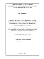
Regarding to the separation between tunnel and existing building by the
Cut-off wall system, the development and expansion of the settlement trough above
the tunnel is mitigated significantly. Moreover, volume of settlement trough is also
minimized as illustrated in Figure 1.1. The effectiveness of this separation depends
not only on geometrical features such as relative dimensions, layout depth, and wall
thickness but also on the hardness of fabricated materials and interactions with the
surrounding soil.
2
Figure 1.1. Cut-off wall method
It can be seen that the Cut-off wall method has a good effectiveness on
strengthening and maintaining the stability of the ground at important construction
locations affected by railway tunneling. This thesis focuses on researching and
analyzing the parameters that determine the efficiency of this method (geometrical
parameters, material characteristics, wall-soil interaction). Combining finite element
simulation and experimental results and observed data analysis will induce an
effective adjustment for the settlement trough equation for this protection method.
1.3.
Aims of the study
The tunnel safety assurance when tunneling design and construction is an
essential issue not only on the safety of the tunneling process but also on the
stability of existing nearby buildings. Solving this problem faces to many relevant
technical and technological challenges. As discussed above, the cut-off wall system
is one of the effective protection methods which has been applied successfully in
Vietnam and all over the world. With the aim of contributing to develop the urban
railway system in Vietnam in future, the thesis will focus on the Cut-off wall system
which will be applied for ground improvement and building protection when
tunneling in soft soils.
3
In ground improvement and protection of existing nearby building in a
tunneling projects, the selection of targeted soil parameters and protection structure
dimensions are often based on the engineer experiences and previous relevant
projects. In addition, soil stabilization and strengthening are issue of concern and
important field of engineering geology. Applying numerical analysis with finite
element model (FEM) combining with the analysis of experimental and observed
data, the derived study results including geometry parameters, material
characteristic, wall-soil interaction will be verified. Based on these results,
designers can select optimize parameters for the implement corresponding
geological and construction conditions of projects. This study will also contribute
important design data in forecasting settlement of ground, understanding of
protecting buildings by cut-off wall method and a basis for developing the further
research.
1.4.
Objectives of the study
Objectives of this thesis is to analyze and evaluate the amplitude of ground
displacements, the change of settlement trough on both sides of cut-off wall system
above the affected area due to tunneling. The research progress uses experimental
results, verify and adjust through finite element (FE) simulation models by using the
Plaxis software (version 8.6) and analytical equations. Details are shown in below:
To study on effects of input parameters in cut-off wall system and
geological condition (dimension, distribution, wall-soil interaction and soil
parameters);
To simulate, verify, adjust the correlation among parameters to the
effectiveness of the system;
To analyze and produce the equivalent equations for the change of the
settlement curve with/without applying the cut-off wall system.
4
CHAPTER 2. LITERATURE REVIEW
2.1.
Background
2.1.1.
Overview of tunneling research in the world
In recent years, underground structures and railway tunnels have attracted
many researchers in the field of geological engineer. Many studies have shown that
the tunnel construction with TBM technology besides the efficiency has many
potential risks, especially during construction process and assessment of total
settlement after tunnel operation. Accordingly, the requirements for the protection
of existing buildings which are nearby affected area are also concentrated. Because
of the important scientific and practical significance of this topic, up to now, there
have been several studies including theoretical and empirical analysis about the
analysis-assessment of settlement and ground improvement in tunneling around the
world.
An overview of the study to evaluate the effects of tunnel construction was
illustrated by the studies of the soil behavior, the total settlement of the ground
above the tunnel structure by Peck (1969) [1]. At that time, the author was also the
first to propose the concept of "Gaussian distribution settlement trough equation"
describing the settlement distribution of the ground displacement above the tunnel.
Subsequently, the publications of Cording and Hansmire (1975) [2], Mair et al.
(1993) [9], Ahmed and Iskander (2010) [3] applied for analysis and recognized of
the appropriateness of this equation. Until now, Peck's settlement equation has been
still widely used in research and design of actual tunnel works. Authors O 'Reily
and author New (1982) [4,5] produced an analysis and derived the relationship of
the horizontal displacement of the ground size to volume and width of the
settlement trough due to soil disturbance during construction. Mair et al. (1973,
1993) [6-10] showed the relationship between the pair of parameters of cover depth
and tunnel diameter with the size of the settlement trough and the maximum
settlement at the tunnel center through comparative analyzes of actual observed data
and small-scale centrifugation experiments. The authors also produced a definition
of the inflection point of the settlement curve equation based on the geological
5
condition parameters at the tunnel construction site.
Studies and assessment of the stability of the tunnel designed and
constructed in soft ground were mentioned by the authors Broms and Bennermark
(1967) [11], Atkinson and Potts (1977). [12], Davis et al. (1980) [13], Kimura and
Mair (1981) [14], Leca and Dormieux (1990) [15], Anagnostou and Kovári (1994)
[16], Jancsecz and Steiner (1994). ) [17], Chambon and Corté (1994) [18], Broere
(2001) [19], Bezuijen and Van Seters (2005) [20] and Mollon et al. (2009a) [21],
Senet, S. and Jimenez, R. (2015) [45], Shiau, J. and A1-Asadi, F. (2020) [46], Pan,
Q. and Dias, D., (2016) [47]. However, these studies had not evaluated and
mentioned the effects of the location of the tunnel located shallowly under the
ground, conditions causing surface settlement and a very large settlement influence
area. In the studies of authors Vu Minh Ngan, Broere and Bosch and [22,23] had
analyzed and evaluated the case of the tunnel lying shallow and gave suggestions on
reducing the ratio of the tunneling depth to the tunnel diameter in order to ensure
soil stability. The study had considered the mechanism of the up-lift effect of the
ground and the stability of the surface face under weak geological conditions.
Measures to stabilize and strengthen the ground, especially in underground
works, are very important, so there have been many studies on this issue in the
world. Some soil improvement methods [37-42] can be mentioned such as changing
geological structure (high pressure mortar, absorbent mortar, soil cement), and
unchanging geological structure (compensating mortar, compacting mortar, wall
system) will be discussed in the Chapter 3. Especially for ground improvement and
protection of existing structures on the ground from impact of tunneling, the
research team from University of Rome (represented by the author Sebastiano
Rampello) had carried out studies considering the behavior of buildings [ 33] and
evaluate the effectiveness by changing the parameters of the diaphragm wall which
were injected between the tunnel and the above structure [34-36].
2.1.2.
Vietnamese authors gradually approach the research on tunnel issues
Regarding Vietnam research situation, studies on tunneling and ground
improvement are not plenty but have also attracted the attention of a few scientists
6
and experts, but still at the level of understanding and analyzing specific problems.
There are general studies such as research on tunneling technology, the adverse
effects of hydro-geological conditions and selected protection solutions by authors
Le Trung Hien [26], Nguyen Hong Duong. [27]. Some analyses through finite
element model have been carried out such as, author Nguyen Van Toan [28]
considered the stress distribution around the tunnel and performed the calculation of
the distance between the two tunnels; authors Tran Quy Duc [29- 32] simulates and
calculates the cases of tunnel layout and size affecting volume loss as well as the
settlement of the ground surface under geological conditions in Ho Chi Minh .
Besides, the studies of author Vu Minh Ngan and colleagues at the Delft University
of Technology have analyzed the volume loss [25] and the effect of the ratio of
depth with tunnel diameter of [22,23] to change the size and width of the settlement
trough. Moreover, there is a theoretical study of determining the influence area of
settlement caused by the construction of the tunnel [24].
Tunnel construction in Vietnam has just been implemented in recent years,
thus the number of studies is still limited. Researches and assessments of ground
improvement in the tunnel construction area and protection of buildings on the
ground have not been paid much attention. Currently, a research by author Phan Sy
Liem (2016) has performed the analysis of the case of ground improvement to
protect Ho Chi Minh City Opera House with high-pressure grouting technology (Jet
grouting) and made comments on the thickness and strength of the wall system.
According to open sources, the thesis of the authors is the legacy research which is
a direction in Vietnam on the cut-off wall method (or diaphragm wall in the ground)
in order to mitigate settlement induced by tunneling. Vu et al. (2020) also presents
some applications of jet-grouting technique in tunneling, in detailed in the
Comment [NVM1]: Cite baif bao co ten em
protection of the Saigon Opera House in Hochiminh Metro line 1 project [48].
2.2.
Overview of settlements induced by tunneling
2.2.1.
The principle of settlements induced by tunneling
2.2.1.1 Ground displacements surrounding the tunnel
The application of the TBM (tunnel boring machine) is proven to bring a
high efficiency and a good applicability to many types of geological conditions.
7
However, due to the phenomenon of rebalancing the mass-stress state causing
displacements of soil particles, the settlement on the ground surface during
excavation is inevitable. It becomes especially dangerous when excavating tunnels
that are shallow through weak and soft geology and close to important nearby
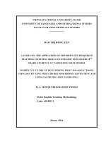
buildings. The displacements of soil masses directly above and surround the tunnel
structure are shown towards the excavated zone of the tunnel. This can be illustrated
by the point-displacement vectors in the centrifugation test results in Mair (1979).
Clay (Mair, 1979)
Dense sand (Potts, 1976)
Figure 2.1. Underground transition vectors of soil surrounding tunnel
Beside the radial displacements due to the mass stress state equilibrium,
volume loss along the tunnel is formed, during drilling and cutting at the excavation
tunnel surface, it also forms the displacement of the ground toward the surface or
another words called "Volume loss". The cumulative sum of volume loss
components is called “total volume loss” after tunnel construction. Based on the
studies of Attewell and Farmer (1974) [43], Cording and Hansmire (1975) [44] and
Mair and Taylor (1999) [8], the details of the displacement components are
described as shown below.
8
Figure 2.2. Volume lost components along the shield [25]
Whereas:
Component 1 (
): Volume loss at tunnel face: soil particles transit toward
due to the disturbance and stress release at the face. This will be controlled
depend on the method of pressure balance during tunneling and number of
monitors in front of.
Component 2 (
): Volume loss along the shield: the radial loss
surrounding the tunnel due to the transition of soil particle into the space
between the shield and ground. This one will be varied based on the value of
extended excavation and designed shape of shield.
Component 3 (
): Volume loss at the gap between the shield and tunnel
segments. When the in-situ segments are fabricated, the movement lap of the
shield leads to the space gap with ground right behind. At this time, high
grade motard will be pump and fill up to avoid the spread of soil. Thus, it
depends on the pressure, volume and grade of the tard which are controlled
by monitors.
Component 4 (
): volume loss along the tunnel due to the soil
consolidation at minor space among the soil particles after the shield: with
the grade formation of motard layer and mass-stress is also formed, it leads
to the short-term and long-term consolidation of ground above the tunnel.
However, this component has little effect compared with the others.
9
Total Volume loss ( ) is combined as equation as:
(
(1)
Beside the theory of these component, by experience of TBM operation after
many years and survey of site monitors from comparable tunnel projects which
constructed around the world, engineers usually provide value of percent of
expected volume loss (2) for initial determination and application to deployment
plans.
(D is diameter of tunnel)
(2)
However, in reality, the level of ground volume loss during construction
depends on a lot of subjective factors (construction process) and objective factors
(geological conditions), so the results and data of experience and observations from
the projects that have been built will be used as references. The assessment of
geological conditions and the selection of suitable construction and support methods
are decisive factors when constructing tunnels.
Currently, the evaluation of the volumetric loss of the ground and the
prediction of the ground surface settlement during tunnel construction are often
based on the results of the finite element modeling process, plus the formulas and
results. experimental results to come up with a suitable solution. In which the
method of Peck 1969 [1] hypothesized that the curvilinear form of the settlement
trough has the most equivalent results with the observed results from the actual
works. Details of this procedure are presented in the following section.
2.2.2.
Overview of ground strengthening
Currently, assessing the impact of tunnel construction on the surrounding
existing structures is a very important issue in the design stage. The stability of
buildings in the affected area is assessed by the displacement of the ground around
the tunnel, the size of the subsidence on the surface, and the distance between the
10
tunnel and the buildings [22]. Therefore, the affected area due to tunnel construction
needs to be analyzed and calculated in order to minimize and mitigate the impact on
surrounding works. Researching on the affected areas caused by tunnel construction
in weak geology, author Vu Minh Ngan (2017) [24] has shown the boundaries of
the affected areas corresponding to specific values of Allowable settlement or
allowable slope angle, details are shown in Figure 3.3. On the basis of these
analysis, engineers can assess risk, damage based on the location of buildings, or
make recommendations decide to monitor, monitor and apply methods of soil
reinforcement and improvement in a timely manner to limit the effects of settlement
on those works.
Figure 2.3. Affected area assessed by the displacement of the ground [24]
Through analyzing the impact between soil parameters along with the
relationship between tunnel depth and diameter to the expansion of the area affected
by ground displacement [24]; showed that by reinforcing the soil mass around the
tunnel (changing soil properties or not changing soil properties), with a certain
distance from the tunnel axis to the location of buildings in the affected area, there
is a much less settlement than allowed can be achieved. On the basis of that result,
11
many methods of strengthening the resistance of soil mass have been improved and
adjusted to be suitable for practical application cases. Each method has its strengths
and scope of application to different geological and construction conditions.
2.2.3.
Ground strengthening methods in tunneling
2.2.3.1 Strengthening by changing soil properties methods
Permeation grouting [37] is the oldest grouting technique. The first
application was in 1802.The principle of this method is filling voids in soil with an
injection grout without changing the soil structure. The grout is pumped into a high
permeable, granular soil to saturate and cement soil particles together in order to
archive a stabilized soil zone for tunneling.
Figure 2.4. Permeation grouting in tunneling [37]
In this technique, the grout can be pumped from the surface and/or from the
tunnel section itself, ahead of the excavation face or from dedicated grouting/pilot
galleries by sleeved pipes (tube à manchette, or TAM). In injection, the coarse
injection grout should be used firstly and then the fine injection grout. This
technique with the TAM can inject different grouts in the same hole at different
times. The pressure used in this technique must not exceed the value h where h
is the overburden pressure and is an empirical factor with the value = 0.3÷3
12
depending on soils. Permeation grouting technique is suitable for sands and gravels.
In tunneling, permeation grouting has been applied in many projects, such as Turin
Railway Interchange, Roma and Napoli metro projects.
Jet grouting [39] In this technique, water or grout is injected with high
pressures in order to disrupt the ground for improving. The first application of this
technique was in England in the 1950s, but the first real practical application was in
Japan. In the early 1970s, rotating jet grouting developed in Japan in the case of
various thickness and somewhat fragile strength. In the middle 1970s, jet grouting
was introduced in Europe and has become popular [7]. Jet grouting can be used to
reinforce almost all soil types, except for peat. In the procedure of jet grouting,
firstly, a jet tube is injected into the soil by using a boring machine, then, the grout
mix is injected with the high pressure in order to erode and mix with the soil. There
are three installation methods of jet grouting depending on geometry as can be seen
in Fig. 3: the single system injects only grout, the double system injects grout
combined with air, the triple system includes three components: grout, jetting water
and compressed air. Jet grouting has been used in many projects, for example,
Galleria Valsesia Milan, Turin railway junction, Panel Grouting building pit
Binnenrotte, Aechertunnel.
Figure 2.5. Jet-grouting in tunneling [39]
Soil mixing measures are based on turning an auger into and out of the soil,
while continuously adding injection fluid under pressure through the hollow core of
13
the soil to make the soil-concrete mixture. There are three different techniques often
applied: Soil Mixed Wall (SMW), Deep Soil Mixing (DSM), and Shallow Soil
Mixing (SSM). This technique is normally applied for improving bearing capacity,
decreasing settlement and increasing stability for structures and embankment. For
example, the railway and road embankment in Malaysia, Japan and Sweden. This
technique also applied for improving the bearing capacity of foundation for high
buildings, and highway-bridge in Poland, as well as excavation control in Japan.
Ground freezing is the technique to make the soil impermeable and increase
the stiffness of the soil by freezing the soil for stability. This technique can be
applied for wide range of soil types, especially fully saturated soils and in difficult
ground conditions. The advantage of this technique is the ability of controlling the
geometry of ground improvement zones by using flexible angle and length of
freezing pipes. However, ground freezing requires refrigeration of massive soil
volumes over a long time, so this technique is expensive comparing to other
methods. When using liquid nitrogen in order to save time, the cost much increases.
The other disadvantage is the expansion volume of frozen water, which can lead to
unexpected heave. Therefore, it requires a careful monitoring in ground freezing
process.
2.2.3.2 Strengthening without changing soil properties
Compensation grouting [40,41] is often used for decreasing building
settlements and distortions to be allowed values, which are indicated in Vu et al.
(2015) or eliminating previous settlements of structures induced by tunneling. In
this method, a grout slurry is injected into the soil between building foundations and
the tunnel lining by sleeve pipes (normally, TAMs), which are often installed with a
drill dig (Fig. 4). In this method, the control of grouting operations works on ground
and structure movements. When fracturing under the foundation, the monitoring
should be accurately controlled both for the settlements of the buildings and the
injection performance. Based on hydraulic fracturing theory, this technique can be
performed in any soil types.
14
Figure 2.6. Compensation in tunneling [40,41]
Compaction grouting [42] is a technique that the soil is compressed by the
grout around the injection point. The grout does not fill the soil pores but remains as
a mass to compact the soil around. In tunnelling, the purpose of this technique is to
compensate previous settlement induced by tunnelling by increasing the soil density
and stress in the soils to heave the structures. Compaction grouting can be used for
compensating the settlement of consolidation or relaxation induced by tunnelling. In
these cases, this technique is applied behind the TBM, from the analysis in Vu et al
(2016).
Figure 2.7. Compaction method in tunneling [42]
Micropiles method system is often used for transferring the structural load to
competent bearing strata. Micropiles were introduced in Italy in the 1950s in the
renovation of historic buildings that had been damaged during the World War II.
15
Then, this technique became popular in Europe, especially in the 1980s. Micropiles
have been used with drilling rigs, grout mixing and a pump for jetting the grout. The
method of installing micropiles can be seen in Fig. 6. Firstly, a drilling rig drills a
hole to designed depths. Then, reinforcements are placed in the hole. The grout is
injected to the hole by pumping. The pile can be injected with further grout under
high pressure to create a larger bearing capacity at the lower part of the pile. In
tunneling, this technique can be used for reinforcing foundations above the tunnel.
Figure 2.8. Micropiles method in tunneling
Cut-off wall system technique uses a wall in the distance between the
buildings and the tunnel in order to minimize the ground movement induced by
tunnelling, which leads to settlement of adjacent buildings as can be seen in Figure
3.9. The cut-off wall also reduces the change of ground water when tunnelling
below water table. The cut-off wall can be formed by steel sheet-piling, slurry
trench walls, concrete diaphragm walls, bored pile walls, grout barriers, mix-inplace barriers or artificial ground freezing.
16
Figure 2.9. Principle of cut-off wall
CHAPTER 3. ANALYSIS METHODOLOGY
3.1.
Methodology
The selected research method is the empirical method combined with the
numerical method (finite element model). Using experimental results and actual
observed data from the construction sites and comparing to the Gaussian equation
for the ground displacement trough above the tunnel in order to establish equivalent
equations with initial parameters. Then, by simulating the problems with finite
element analysis models, together with analytical equations, the relationship
between the input parameters and the impact of the cut-off wall system on the
change of ground displacement is determined. Input parameters including
geometrical dimensions, and soil-wall interactions will be respectively adjusted to
produce the most appropriate combination corresponding to a particular geological
condition. This study approach can derive the change of displacement and
settlement trough equation and determine the stability of the ground and the impact
on the geological area behind the cut-off wall system.
17
Figure 3.1. Study methodology
3.2.
Mitigating measure selection
In tunnel design and construction, the choice of mitigating measures often
depends on the cost of projects, the speed of carrying out the work, the reduction of
uncertainties between design and construction and the safety when tunneling. The
selection of soil improvement method in tunneling projects is a summary of the
assessment of ground improvement on the flexibility, feasibility, durability and the
speed of carrying out of work. In the case of tunneling in peat and soft clay, as
investigated in the volume loss of the tunneling face, along the shield, at the tail and
in consolidation might be very large. The ground improvement methods combined
with reinforcement methods for the tunneling face are recommended to be applied
in these cases. Careful control when tunneling is also recommended in these cases.
The mitigating measures for improving the soil properties are often applied
before tunneling and the injected grout quantity can be estimated in the laboratory
in order to achieve the required soil parameters before actually being applied in
projects. Meanwhile, the measures of compensating settlement without changing the
soil properties are usually applied to compensate the settlement induced by
tunneling. The cavity expansion methods can be used to estimate the quantity of
required grout in these measures. Therefore, the selection in this study will depend
on following requirements:
It is not necessary to improve a large area of land around the tunnel;
Ensure separating the area of important building from the influence zone of
the tunnel while excavating;
18