Training manual generator auxiliary system design Tài liệu nhiệt điện Turbine
Bạn đang xem bản rút gọn của tài liệu. Xem và tải ngay bản đầy đủ của tài liệu tại đây (2.34 MB, 32 trang )
Generator Auxiliary System
Design
2013. 10
Generator Design Team
This document is the informational asset of Doosan Heavy Industries & Construction. Thus, unauthorized access, revision, distribution and copying of this document are strictly prohibited.
SUMMARY
1. Stator Winding Liquid Cooling System
2. Generator Shaft Seal System
3. Generator Gas Control System
2
Table of Contents
1. STATOR WINDING LIQUID COOLING SYSTEM
1.1 Function
1.2 Operating Procedure
1.3 Monitoring (Alarm)
1.4 Components
3
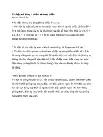
1.1 Function
• COOLING OF GENERATOR STATOR WINDING
• CONTROL OF COOLING WATER FLOW AND TEMPERATURE
• MAINTAINING CONDUCTIVITY OF COOLING WATER
(Remove the Ion from cooling water )
Hot liquid
Cooled liquid
4
1.1 Function
DESIGN
AUTOMATIC CONTROL OF COOLING WATER TEMP.
: INLET TEMPERATURE MIN 42 DEG C ~ MAX 46 DEG C
MAINTAINING CONDUCTIVITY OF COOLING WATER
BELOW 0.5 MICROMHO/CM (microsiemens)
FORMING BACK UP WATER CIRCUIT TO PREVENT LOSS
OF COOLING WATER
(Standby pump motor for continuous cooling ,
Pump-A or Pump-B, 2 x 100%)
FORMING CLOSED LOOP TO MAINTAIN CONDUCTIVITY
OF COOLING WATER
STAINLESS MATERIAL USED TO PREVENT CORROSION
5
1.2 Operating Procedure
THE GENERATOR STATOR WINDING LIQUID COOLING SYSTEM SHALL PROVIDE A CONTINUOUS
SUPPLY OF COOLING WATER TO THE GENERATOR STATOR WINDING.
Make-up Water Come into System
GENERATOR
Make-up Filter
Strainer
Deionizer
Main Filter
Storage Tank
Flow Cont. Valve
Pump A or B Run
Make-up Filter
Cooler A or B Run
Temp. Cont. Valve
6
1.3 Monitoring (Alarm)
Storage Tank Level High / Low
Water Pump Discharge Pressure Low
Main Filter & Deionizer Differential Pressure High
Cooling Water Flow : Low-Low
Cooling Water Conductivity High/High-High
Cooling Water Temp. High / High-High
Cooling Water Inlet Pressure : Low-Low
7
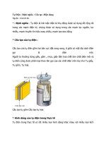
1.4 Components
STATOR WINDING COOLIN WATER TANK
The stator winding cooling water tank has several functions.
It is a source of water for the pumps and maintains a water
level which satisfies pump suction head requirements.
A liquid level switch is mounted in the tank to provide high
and low water level alarm contacts.
PUMP
STORAGE TANK
STATOR COOLANT PUMP ( 2 x 100% )
Two full capacity pumps are supplied to meet redundancy
requirements.
8
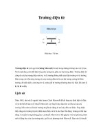
1.4 Components
STATOR WATER COOLER ( 2 x 100% )
2 x 100% capacity plate type heat exchangers are supplied.
The deionized water flows through the hot side of cooler.
The closed cooling water flows through the cold side of
cooler.
MAIN FILTER
A filter capable of removing all particles larger than three
microns is installed after the flow control valve to prevent
plugging the small passages in the stator bars.
MAIN FILTER
STATOR COOLER
9
1.4 Components
MAKE-UP FILTER
A filter capable of removing all particles larger than three
microns is installed before the Deionizer.
DEIONIZER
The deionizer is a stainless steel tank holding a quantity of
resin.
The resin cannot be regenerated and must be replaced if
conductivity cannot be maintained below 0.5 micromho/cm.
DEIONIZER
MAKEUP FILTER
10
Table of Contents
2. GENERATOR SHAFT SEAL SYSTEM
2.1 Function
2.2 Operating Procedure
2.3 Monitoring (Alarm)
2.4 Components
2.5 Caution
11
2.1 Function
• PREVENT THE HYDROGEN GAS LEAKAGE FROM GENERATOR INSIDE
• REMOVING DISSOLVED GAS FROM OIL
RSOP
12
2.1 Function
DESIGN
MAINTAIN PRESSURE OF SEAL OIL 0.56 kg/cm2 (8 PSID)
HIGHER THAN GENERATOR GAS PRESSURE
IN ORDER TO ENSURE THE CONTINUOUS SUPPLY OF OIL TO
THE SEALS, AN EMERGENCY SEAL OIL PUMP (ESOP) IS
PROVIDED, AND IS AUTOMATICALLY ACTIVATED IN THE
EVENT OF FAILURE OF THE MAIN SEAL OIL PUMP (MSOP).
OIL SUPPLIED FROM TURBINE LUBE OIL SYSTEM
13
2.2 Operating Procedure
THE GENERATOR SHAFT SEAL OIL SYSTEM PROVIDES OIL TO THE HYDROGEN SEALS TO
PREVENT THE HYDROGEN GAS LEAKAGE FROM GENERATOR INSIDE
GENERATOR TE / CE
SEAL RING
H2 Side
Air Side
SODE
FILTER
ADT
Float Trap
TBN Lube Oil System
To Roof
Inlet Strainer
Vent
Diff. Press. Control Valve
Vacuum
Storage Tank
SOVP
ESOP
RSOP
MSOP
14
2.3 Monitoring (Alarm)
Vacuum Tank Level High / Low
Seal Oil Tank Vacuum Low
Differential Seal Oil Pressure Low
Seal Oil Feed Pressure Low
Seal Oil Filter & Strainer Differential Pressure High
Seal Oil Drain Enlargement Over Flow
: Liquid Level Detector Full
15
2.4 Components
VACUUM TANK
During normal operation, seal oil is supplied by the
lube oil header .
Seal oil enters at the bottom of the tank, first
through a float valve, and the through a spray
nozzle. The float valve functions to close on rising
oil level. The spray nozzle is provided to break the
oil into a fine spray and facilitate the removal of
gasses in solution.
VACUUM TANK
VACUUM PUMP
The seal oil shall be vacuum treated to removed
dissolved air and associated water vapor.
MAIN SEAL OIL PUMP
MSOP
VACUUM PUMP
The main seal oil pump (MSOP) is a positive
displacement, rotary screw type pump, powered by
an AC motor. During normal operation, this pump
takes oil from the bottom of the vacuum tank for
circulation through the seal oil system.
16
2.4 Components
EMERGENCY SEAL OIL PUMP
In order to ensure the continuous supply of oil to
the seals, an emergency seal oil pump (ESOP) is
provided, and is automatically activated in the event
of failure of the main seal oil pump. The pump is a
displacement, rotary screw type pump, driven by a
DC motor to ensure operation in case the main
pump failure is due to loss of AC power
RECIRCULATING SEAL OIL PUMP
DPCV
ESOP
The recirculating seal oil pump (RSOP) is provided
to take oil from the bottom of the vacuum tank and
discharge it directly back into the vacuum tank
through a series of spray nozzle as a further aid to
degasification. The pump is a positive
displacement, rotary screw type pump, powered by
an AC motor.
DIFF. PRESSURE CONTROL VALVE
RSOP
This valve functions to control the pressure difference
between the machine gas pressure and the seal oil pressure.
The valve is set to maintain a pressure of 0.56 above
machine gas pressure.
17
2.4 Components
FILTER
Particulate matter shall be removed from the oil by
filter. The filter elements are rated at 5 microns.
LIQUID LEVEL DETECTOR
A liquid level detector for SODE is provided to warn
of an increasing level in the seal oil drain
enlargement which could lead to oil backing up into
the generator casing.
FILTER
18
2.4 Components
FLOAT TRAP
Seal oil flows from the seal oil drain enlargement
into the float trap, which allows oil to flow through
the float valve while preventing hydrogen machine
gas from escaping.
19
2.5 CAUTION (Operate Float Trap)
20
2.5 CAUTION
CAUTION of seal oil overflow
BY SEAL OIL DRAIN LINE PLUGGING
- If float valve of float trap is out of control or if seal oil drain pipe is plugged or if valve is
closed opposite to normal open status, seal oil can be overflowed into Generator inside.
- By Liquid detector, it can be monitored and alarmed to operator before over flood.
BY FLOAT TRAP INEXPERIENCE OPERATION
- It was normally happened at initial operation under 0 ~ 0.4 kg/cm 2g pressurizing.
- Before start, stop operating Generator, be caution to operate float trap.
- Refer to the page 19 not to waste the recovery time, money and quality.
- By Liquid detector, it can be monitored and alarmed to operator before over flood.
21
Table of Contents
3. GENERATOR GAS CONTROL SYSTEM
3.1 Function
3.2 Operating Procedure
3.3 Monitoring (Alarm)
3.4 Components
22
3.1 Function
• CONTROL OF HYDROGEN GAS INSIDE GENERATOR
H2 : The generator interior components (rotor, core) are cooled by H2 gas.
CO2 : CO2 Gas is used as an intermediate gas so that air and hydrogen do not mix
inside the generator.
• MONITORING HYDROGEN GAS CONDITION
23
3.1 Function
DESIGN
CONSIDER SAFE SUPPLY AND DISCHARGE OF HYDROGEN GAS
CO2 Gas is used as an intermediate gas so that air and hydrogen
do not mix inside the generator.
INCREASED GENERATOR CAPACITY WITH SAME SIZE
COMPARED TO AIR COOLING
Hydrogen cooling capacity compared to air : 3~4 times
24
3.2 Operating Procedure
The gas control system has the dual function of supplying hydrogen (H 2) to the generator
as required to maintain selected pressure and to supply carbon dioxide (CO 2) and H2 to the
generator for purging and filling operations.
The CO2 gas is used as intermediate median in order to prevent hydrogen gas and air.
Therefore there will be not hydrogen gas and air mixture
REMOVING AIR
FROM THE GENERATOR
GENERATOR STANDSTILL
SHAFT SEALING SYSTEM OPERATION
CO2 GAS WILL BE SUPPLIED TO PURGE AIR
GENERATOR WILL BE FILLED WITH CO22 GAS
( MORE THAN CO22 70%).
25