Tài liệu Công nghệ phần mềm P9 doc
Bạn đang xem bản rút gọn của tài liệu. Xem và tải ngay bản đầy đủ của tài liệu tại đây (259.94 KB, 42 trang )
1
Architecture and the UML
2
Models, Views, and Diagrams
Use Case
Diagrams
Use Case
Diagrams
Use Case
Diagrams
Scenario
Diagrams
Scenario
Diagrams
Collaboration
Diagrams
State
Diagrams
State
Diagrams
Component
Diagrams
Component
Diagrams
Component
Diagrams
Deployment
Diagrams
State
Diagrams
State
Diagrams
Object
Diagrams
Scenario
Diagrams
Scenario
Diagrams
Statechart
Diagrams
Use Case
Diagrams
Use Case
Diagrams
Sequence
Diagrams
State
Diagrams
State
Diagrams
Class
Diagrams
Activity
Diagrams
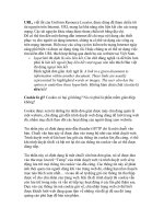
A model is a complete
description of a system
from a particular
perspective
Models
3
Use Case Model
Use Case
Diagrams
Collaboration
Diagrams
Component
Diagrams
Deployment
Diagrams
Object
Diagrams
Statechart
Diagrams
Sequence
Diagrams
Class
Diagrams
Activity
Diagrams
Use Case
Views
Design
Views
Depl.
Views
Impl.
Views
Analysis
Views
Test
Views
Use Case
Views
Design
Views
Depl.
Views
Impl.
Views
Analysis
Views
Test
Views
4
Analysis & Design Model
Use Case
Diagrams
Collaboration
Diagrams
Component
Diagrams
Deployment
Diagrams
Object
Diagrams
Statechart
Diagrams
Sequence
Diagrams
Class
Diagrams
Activity
Diagrams
Use Case
Model
Design
Model
Depl.
Model
Impl.
Model
Analysis
Model
Test
Model
Incl. subsystems
and packages
Use Case
Views
Design
Views
Depl.
Views
Impl.
Views
Analysis
Views
Test
Views
5
Deployment and Implementation
Model
Use Case
Diagrams
Collaboration
Diagrams
Component
Diagrams
Deployment
Diagrams
Object
Diagrams
Statechart
Diagrams
Sequence
Diagrams
Class
Diagrams
Activity
Diagrams
Use Case
Model
Design
Model
Depl.
Model
Impl.
Model
Analysis
Model
Test
Model
Incl. active classes
and components
Use Case
Views
Design
Views
Depl.
Views
Impl.
Views
Analysis
Views
Test
Views
6
Test Model
Use Case
Diagrams
Collaboration
Diagrams
Component
Diagrams
Deployment
Diagrams
Object
Diagrams
Statechart
Diagrams
Sequence
Diagrams
Class
Diagrams
Activity
Diagrams
Use Case
Model
Design
Model
Depl.
Model
Impl.
Model
Analysis
Model
Test
Model
Test model refers to
all other models and
uses corresponding
diagrams
Use Case
Views
Design
Views
Depl.
Views
Impl.
Views
Analysis
Views
Test
Views
7
Use case - functions of a system from the user's point of view
Sequence diagrams -illustrates object interactions arranged in a time sequence.
Class diagrams -static structure in terms of classes and relationships
Activity diagrams -behavior of an operation as a set of actions
State chart diagrams -behavior of a class in terms of states
Collaboration diagrams -spatial representation of objects, links, and interactions
Object diagrams -objects and their relationships and correspond to (simplified
collaboration diagrams that do not represent message broadcasts)
Component diagrams -physical components of an application
Deployment diagrams -deployment of components on particular pieces of hardware
8
Actors
An actor is someone or some thing that
must interact with the system under
development
Tranc coord
Buyerr
seller
Security system
9
Use Cases
A use case is a pattern of behavior the system exhibits
- Each use case is a sequence of related transactions
performed by an actor and the system in a dialogue
Actors are examined to determine their needs
- Buyer – post an rfq
- seller – respond to rfq
- Data validator – validate
- Dep manager deploy
deploy
post an rfq
Validate
Principal actors
Secondary actors
External hardware
Other systems
10
Use Cases
A flow of events document is created for
each use cases
- Written from an actor point of view
Details what the system must provide to
the actor when the use cases is executed
Typical contents
- How the use case starts and ends
- Normal flow of events
- Alternate flow of events
- Exceptional flow of events
11
Uses and Extends Use Case
Relationships
As the use cases are documented, other
use case relationships may be discovered
- A uses relationship shows behavior that is
common to one or more use cases
- An extends relationship shows optional
behavior
- Communicates shows specific functions
Post an rfq
<<uses>>
Logon validation
<<uses>>
validate
12
Use Case Realizations
The use case diagram presents an outside
view of the system
Interaction diagrams describe how use
cases are realized as interactions among
societies of objects
Two types of interaction diagrams
- Sequence diagrams
- Collaboration diagrams
13
Sequence Diagram
A sequence diagram displays object
interactions arranged in a time sequence
: Buyer
registration
form
registration
manager
profile
1: fill in info
2: submit
3: add user
4: add interests
5: save information
6: add info
7: add
section 1
14
Class Diagrams
A class diagram shows the existence of
classes and their relationships in the logical
view of a system
UML modeling elements in class diagrams
- Classes and their structure and behavior
- Association, aggregation, dependency, and
inheritance relationships
- Multiplicity and navigation indicators
- Role names
15
Classes
A class is a collection of objects with common
structure, common behavior, common
relationships and common semantics
Classes are found by examining the objects in
sequence and collaboration diagram
A class is drawn as a rectangle with three
compartments
Classes should be named using the vocabulary of
the domain
- Naming standards should be created
- e.g., all classes are singular nouns starting with a
capital letter
16
«signal» transaction within a state machine.
«interface» description of visible operations.
«metaclass»The class of a class
«utility»A class reduced to the concept of module
1. Attributes and Operations
2. Stereotype
3. Visibility of Attributes
and Operations
Classes
17
Extensibility Mechanisms
Stereotype
Tagged value
Constraint
18
Common Elements
19
Common Mechanisms
20
Packages
Data Types
21
Extending the UML
Stereotypes can be used to extend the
UML notational elements
Stereotypes may be used to classify and
extend associations, inheritance
relationships, classes, and components
Examples:
- Class stereotypes: boundary, control, entity,
utility, exception
- Inheritance stereotypes: uses and extends
- Component stereotypes: subsystem
22
Classes
Registration Form
Registration
Service
manager
Buyer
Service Offering
Tranc coord
payment
23
Operations
The behavior of a class is represented by
its operations
Operations may be found by examining
interaction diagrams
registration
form
registration
manager
3: add member count =count +1
RegistrationManager
Add member()
24
Attributes
The structure of a class is represented by
its attributes
Attributes may be found by examining
class definitions, the problem
requirements, and by applying domain
knowledge
Each User has a name
, location, interests,
and authentification
user
name
location
interests
25
Relationships
Relationships provide a pathway for
communication between objects
Sequence and/or collaboration diagrams are
examined to determine what links between
objects need to exist to accomplish the behavior -
- if two objects need to “talk” there must be a link
between them
Three types of relationships are:
- Association
- Aggregation
- Dependency