Tài liệu Parallel Port Complete: Programming, Interfacing, & Using the PC''''s Parallel Printer Port ppt
Bạn đang xem bản rút gọn của tài liệu. Xem và tải ngay bản đầy đủ của tài liệu tại đây (703.63 KB, 63 trang )
Parallel Port
Complete
Programming, Interfacing,
& Using the PC's
Parallel Printer
Port
I
NCLUDES
DISK
r
I
ncludes EPP ECP
I
EEE-1284
r
Source code i n
Visual Basic
r
User tips
Jan Axelson
Table of Contents
I
ntroduction ix
1
Essentials 1
Parallel Port Complete
Defining the Port 1
Port Types
System Resources 4
Addressing
Interrupts
DMA Channels
Finding Existing Ports
Configuring 6
Port Options
Drivers
Adding a Port
Port Hardware 9
Connectors
The Circuits Inside
Cables
Multiple Uses for One Port 11
Security Keys
Alternatives to the Parallel Port 13
Serial Interfaces
Other Parallel Interfaces
Custom I/O
Cards
PC Cards
2
Accessing Ports 17
The Signals 17
Centronics Roots
Naming Conventions
The Data Register
The Status Register
The Control Register
Bidirectional Ports
Addressing 24
Finding Ports
Direct Port 1/O 26
Programming in Basic
Other Programming Languages
Other Ways to Access Ports 31
LPT Access in Visual Basic
Windows API Calls
DOS and BIOS Interrupts
3
Programming Issues 39
Options for Device Drivers 39
Simple Application Routines
DOS Drivers
Windows Drivers
Custom Controls
Speed 45
Hardware Limits
Software Limits
4
Programming Tools 53
Routines for Port Access 53
Data Port Access
Status Port Access
Control Port Access
Bit Operations
A Form Template 60
Saving Initialization Data
Finding, Selecting, and Testing Ports
5
Experiments 85
Viewing and Controlling the Bits 85
Circuits for Testing
Output Types
Component Substitutions
i
v
Parallel Port Complete
Cables & Connectors for Experimenting 99
Making an Older Port Bidirectional 100
Cautions
The Circuits
The Changes
6
I
nterfacing
105
Parallel Port Complete
Port Variations 105
Drivers and Receivers
Level 1 Devices
Level 2 devices
Interfacing Guidelines 110
General Design
Port Design
Cable Choices 112
Connectors
Cable Types
Ground Returns
36-wire Cables
Reducing Interference
Line Terminations
Transmitting over Long Distances
Port-powered Circuits 124
When to Use Port Power
Abilities and Limits
Examples
7
Output Applications
129
Output Expansion 129
Switching Power to a Load 132
Choosing a Switch
Logic Outputs
Bipolar Transistors
MOSFETs
High-side Switches
Solid-state Relays
Electromagnetic Relays
Controlling the Bits
X-10 Switches
Signal Switches 143
Simple CMOS Switch
Controlling a Switch Matrix
Displays 148
8
I
nput Applications
149
Reading a Byte 149
v
9
Synchronous Serial Links 165
10
Real-time Control
183
Periodic Triggers 183
11
Modes for Data Transfer 203
Vi
Latching the Status Inputs
Latched Input Using Status and Control Bits
5 Bytes of Input
Using the Data Port for Input
Reading Analog Signals 154
Sensor Basics
Simple On/Off Measurements
Level Detecting
Reading an Analog-to-digital Converter
Sensor Interfaces
Signal Conditioning
Minimizing Noise
Using a Sample and Hold
About Serial Interfaces 165
A Digital Thermometer 166
Using the DS 1620
The Interface
An Application
Other Serial Chips
Simple Timer Control
Time-of-day Triggers
Loop Timers
Triggering on External Signals 189
Polling
Hardware Interrupts
Multiple Interrupt Sources
Port Variations
The IEEE 1284 Standard 203
Definitions
Communication modes
Detecting Port Types 207
Using the New Modes
Port Detecting in Software
Disabling the Advanced Modes
Negotiating a Mode 210
Protocol
Controller Chips 212
Host Chips
Peripheral Chips
Peripheral Daisy Chains
Parallel Port Complete
15
E
Parallel
12
Compatibility and Nibble Modes 223
13
Byte Mode 249
14
Enhanced Parallel Port: EPP 267
15
Extended Capabilities Port:
ECP
Parallel Port Complete
Programming Options 220
Compatibility Mode 223
Handshaking
Variations
Nibble Mode 228
Handshaking
Making a Byte from Two Nibbles
A Compatibility & Nibble-mode Application 232
About the 82C55 PPI
Compatibility and Nibble-mode Interface
Handshaking 249
Applications 250
Compatibility & Byte Mode
Compatibility, Nibble & Byte Mode with Negotiating
Inside the EPP 267
Two Strobes
The Registers
Handshaking 269
Four Types of Transfers
Switching Directions
Timing Considerations
EPP Variations 275
Use of nWait
Clearing Timeouts
Direction Control
An EPP Application 277
The Circuit
Programming
ECP Basics 286
The FIFO
Registers
Extended Control Register (ECR)
Internal Modes
ECP Transfers 289
Forward transfers
Reverse Transfers
Timing Considerations
Interrupt Use
285
Using the FIFO
Other ECP Modes 296
Fast Centronics
Test Mode
Configuration Mode
An ECP Application 298
16
PC-to-PC Communications 305
A PC-to-PC Cable 305
Dos and Windows Tools 306
MS-DOS's Interlnk
Direct Cable Connection
A PC-to-PC Application 311
Appendices
A
Resources 323
B
Microcontroller Circuit 327
C
Number Systems 329
I
ndex 333
viii
Parallel Port Complete
Parallel
F
h
a
0
0
P
0
u
ti
O
cl
it
w
e
P
1
I
le
I
ntroduction
I
ntroduction
From its origin as a simple printer interface, the personal computer's parallel port
has evolved into a place to plug in just about anything you might want to hook to
a computer. The parallel port is popular because it's versatile-you can use it for
output, input, or bidirectional links-and because it's available-every PC has
one.
Printers are still the most common devices connected to the port, but other popular
options include external tape and disk drives and scanners. Laptop computers may
use a parallel-port-based network interface or joystick. For special applications,
there are dozens of parallel-port devices for use in data collection, testing, and
control systems. And the parallel port is the interface of choice for many
one-of-a-kind and small-scale projects that require communications between a
computer and an external device.
In spite of its popularity, the parallel port has always been a bit of a challenge to
work with. Over the years, several variations on the original port's design have
emerged, yet there has been no single source of documentation that describes the
port in its many variations.
I
wrote this book to serve as a practical, hands-on guide to all aspects of the paral-
lel port. It covers both hardware and software, including how to design external
Parallel Port Complete
i
x
I
ntroduction
circuits that connect to the port, as well as how to write programs to control and
monitor the port, including both the original and improved port designs.
Who should read this book?
The book is designed to serve readers with a variety of backgrounds and interests:
Programmers will find code examples that show how to use the port in all of its
modes. If you program in Visual Basic, you can use the routines directly in your
programs.
For hardware designers, there are details about the port circuits and how to inter-
face them to the world outside the PC. I cover the port's original design and the
many variations and improvements that have evolved. Examples show how to
design circuits for reliable data transfers.
System troubleshooters can use the programming techniques and examples for
finding and testing ports on a system.
Experimenters will find dozens of circuit and code examples, along with expla-
nations and tips for modifying the examples for a particular application.
Teachers and students have found the parallel port to be a handy tool for experi-
ments with electronics and computer control. Many of the examples in this book
are suitable as school projects.
And last but not least, users, or anyone who uses a computer with printers or other
devices that connect to the parallel port, will find useful information, including
advice on configuring ports, how to add a port, and information on cables, port
extenders, and switch boxes.
What's Inside
This book focuses on several areas related to the parallel port:
Using the New Modes
Some of the most frequently asked parallel-port questions relate to using, pro-
gramming, and interfacing the
port
in the new, advanced modes, including the
enhanced parallel
port
(EPP), the extended capabilities
port
(ECP), and the
PS/2-type, or simple bidirectional,
port.
This book covers each of these. Examples
show how to enable a mode, how to use the mode to transfer data, and how to use
software negotiation to enable a PC and peripheral to select the best mode avail-
able.
Parallel Port Complete
Visu
Micrc
PCs,
programs
enables
the ft
includ
registers
Becau
writes
add th
and 3:
Applications
Besides
ple circuits
cuits.
load,
port can
how ti
serial
trigger
calend
as the
Cables
The proper
one th
cable,
PC-to-PC
Although
and a I
ring in
link us
own programs
Parallel Port
I
ntroduction
About the Program Code
Every programmer has a favorite language. The choices include various imple-
mentations of Basic, CIC++, and Pascal/Delphi, and assembly language.
For the program examples in this book, I wanted to use a popular language so as
many readers as possible could use the examples directly, and this prompted my
decision to use Microsoft's Visual Basic for Windows. A big reason for Visual
Basic's popularity is that the programming environment makes it extremely easy
to add controls and displays that enable users to control a program and view the
results.
However, this book isn't a tutorial on Visual Basic. It assumes you have a basic
understanding of the language and how to create and debug a Visual-Basic pro-
gram.
I developed the examples originally using Visual Basic Version 3, then ported
them to Version 4. As much as possible, the programs are designed to be compat-
ible with both versions, including both 16- and 32-bit Version-4 programs. The
companion disk includes two versions of each program, one for Version 3 and one
for 16- and 32-bit Version 4 programs.
One reason I decided to maintain compatibility with Version 3 is that the standard
edition of Version 4 creates 32-bit programs only. Because Windows 3.1 can't run
these programs, many users haven't upgraded to Version 4. Also, many paral-
lel-port programs run on older systems that are put to use as dedicated controllers
or data loggers. Running the latest version of Windows isn't practical or necessary
on these computers.
Of course, in the software world, nothing stays the same for long. Hopefully, the
program code will remain 'compatible in most respects with later versions of
Visual Basic.
Compatibility with Version 3 does involve some tradeoffs. For example, Version
3 doesn't support the Byte variable type, so my examples use Integer variables
even where Byte variables would be appropriate (as in reading and writing to a
byte-wide port). In a few areas, such as some Windows API calls, I've provided
two versions, one for use with 16-bit programs, Version 3 or 4, and the other for
use with Version 4 programs, 16- or 32-bit.
In the program listings printed in this book, I use Visual Basic 4's line-continua-
tion character ( _) to extend program lines that don't fit on one line on the page. In
other words, this:
PortType =
Left$(ReturnBuffer, NumberOfCharacters)
is the same as this:
xii
Parallel Port Complete
PortType = Left$(ReturnBuffer, NumberOfCharacters)
To remain compatible with Version 3, the code on the disk doesn't use this fea-
ture.
Most of the program examples are based on a general-purpose Visual-Basic form
and routines introduced early in the book. The listings for the examples in each
chapter include only the application-specific code added to the listings presented
earlier. The routines within a listing are arranged alphabetically, in the same order
that Visual Basic displays and prints them.
Of course, the concepts behind the programs can be programmed with any lan-
guage and for any operating system. In spite of Windows' popularity, MS-DOS
programs still have uses; especially for the type of control and monitoring pro-
grams that often use the parallel port. Throughout, I've tried to document the code
completely enough so that you can translate it easily into whatever programming
language and operating system you prefer.
Several of the examples include a parallel-port interface to a microcontroller cir-
cuit. The companion disk has the listings for the microcontroller programs.
About the Example Circuits
I
ntroduction
This book includes schematic diagrams of circuits that you can use or adapt in
parallel-port projects. In designing the examples, I looked for circuits that are as
easy as possible to put together and program. All use inexpensive, off-the-shelf
components that are available from many sources.
The circuit diagrams are complete, with these exceptions:
Power-supply and ground pins are omitted when they are in standard locations
on the package (bottom left for ground, top right for power, assuming pin 1 is
top left).
Power-supply decoupling capacitors are omitted. (This book explains when and
how to add these to your circuits.)
Some chips may have additional, unused gates or other elements that aren't
shown.
The manufacturers' data sheets have additional information on the components.
Parallel Port Complete
Xii i
I
ntroduction
Conventions
These are the typographic conventions used in this book:
Thanks!
Corrections and Updates
In researching and putting together this book, I've done my best to ensure that the
information is complete and correct. I built and tested every circuit and tested all
of the program code, most of it multiple times. But I know from experience that
on the way from test to publication, errors and omissions do occur.
Any corrections or updates to this book will be available at Lakeview Research's
World Wide Web site on the Internet at
. Thi
s
is also the place
to come for links to other parallel-port information on the Web, including data
sheets for parallel-port controllers and software tools for parallel-port program-
ming.
Finally, I want to say thanks to everyone who helped make this book possible. I
credit the readers of my articles in
The Microcomputer Journal for first turning
me on to this topic with their questions, comments, and article requests. The series
I
wrote for the magazine in 1994 was the beginning of this book.
Others deserving thanks are product vendors, who answered many questions, and
the Usenet participants who asked some thought-provoking questions that often
sent me off exploring areas I wouldn't have thought of otherwise.
Special thanks to SoftCircuits (PO Box 16262, Irvine, CA 92713, Compuserve
72134,263, WWW: ) for the use of Vbasm.
AV
Parallel Port Complete
Item
Convention Example
Signal name
italics
Busy, DO
Active-low signal
leading n
nAck nStrobe
Signal complement
overbar
CO, S7 (equivalent to
-
CO, -S7 or /CO, /S7)
Program code
monospace font
DoEvents, End
,
Sub
File name
italics
win.ini, inpout16.d11
Hexadecimal number
trailing h
3BCh (same as &h3BC in
Visual Basic)
Essentials
Defining the Port
Parallel Port Complete
Essentials
A first step in exploring the parallel port is learning how to get the most from a
port with your everyday applications and peripherals. Things to know include
how to find, configure, and install a port, how and when to use the new bidirec-
tional, EPP, and ECP modes, and how to handle a system with multiple paral-
lel-port peripherals. This chapter presents essential information and tips relating
to these topics.
What is the "parallel port"? In the computer world, a port is a set of signal lines
that the microprocessor, or CPU, uses to exchange data with other components.
Typical uses for ports are communicating with printers, modems, keyboards, and
displays, or just about any component or device except system memory. Most
computer ports are digital, where each signal, or bit, is 0 or 1. A parallel port
transfers multiple bits at once, while a serial port transfers a bit at a time (though it
may transfer in both directions at once).
This book is about a specific type of parallel port: the one found on just about
every PC, or IBM-compatible personal computer. Along with the RS-232 serial
port, the parallel port is a workhorse of PC communications. On newer PCs, you
Chapter 1
2
may find other ports such as SCSI, USB, and IrDA, but the parallel port remains
popular because it's capable, flexible, and every PC has one.
The term
PC-compatible,
or PC for short, refers to the IBM PC and any of the
many, many personal computers derived from it. From another angle, a PC is any
computer that can run Microsoft's MS-DOS operating system and whose expan-
sion bus is compatible with the ISA bus in the original IBM PC. The category
includes the PC, XT, AT, PS/2, and most computers with 80x86, Pentium, and
compatible CPUs. It does not include the Macintosh, Am iga, or IBM mainframes,
though these and other computer types may have ports that are similar to the par-
allel port on the PC.
The original PC's parallel port had eight outputs, five inputs, and four bidirec-
tional lines. These are enough for communicating with many types of peripherals.
On many newer PCs, the eight outputs can also serve as inputs, for faster commu-
nications with scanners, drives, and other devices that send data to the PC.
The parallel port was designed as a printer port, and many of the original names
for the port's signals
(PaperEnd, AutoLineFeed)
reflect that use. But these days,
you can find all kinds of things besides printers connected to the port. The term
peripheral,
or
peripheral device
is
a catch-all category that includes printers,
scanners, modems, and other devices that connect to a PC.
Port Types
As the design of the PC evolved, several manufacturers introduced improved ver-
sions of the parallel port. The new port types are compatible with the original
design, but add new abilities, mainly for increased speed.
Speed is important because as computers and peripherals have gotten faster, the
jobs they do have become more complicated, and the amount of information they
need to exchange has increased. The original parallel port was plenty fast enough
for sending bytes representing ASCII text characters to a dot-matrix or
daisy-wheel printer. But modern printers need to receive much more information
to print a page with multiple fonts and detailed graphics, often in color. The faster
the computer can transmit the information, the faster the printer can begin pro-
cessing and printing the result.
A fast interface also makes it feasible to use portable, external versions of periph-
erals that you would otherwise have to install inside the computer. A parallel-port
tape or disk drive is easy to move from system to system, and for occasional use,
such as making back-ups, you can use one unit for several systems. Because a
backup may involve copying hundreds of Megabytes, the interface has to be fast
to be worthwhile.
Parallel Port Complete
Essentials
This book covers the new port types in detail, but for now, here is a summary of
the available types:
Original (SPP)
The parallel port in the original IBM PC, and any port that emulates the original
port's design, is sometimes called the SPP, for standard parallel port, even though
the original
port
had no written standard beyond the schematic diagrams and doc-
umentation for the IBM PC. Other names used are AT-type or
ISA-compatible.
The
port
in the original PC was based on an existing Centronics printer interface.
However, the PC introduced a few differences, which other systems have contin-
ued.
SPPs can transfer eight bits at once to a peripheral, using a protocol similar to that
used by the original Centronics interface. The SPP doesn't have a byte-wide input
port,
but for PC-to-peripheral transfers, SPPs can use a Nibble mode that transfers
each byte 4 bits at a time. Nibble mode is slow, but has become popular as a way
to use the parallel
port
for input.
PS/2-type (Simple Bidirectional)
An early improvement to the parallel port was the bidirectional data port intro-
duced on IBM's model PS/2. The bidirectional port enables a peripheral to trans-
fer eight bits at once to a PC. The term PS/2-type has come to refer to any parallel
port that has a bidirectional data port but doesn't support the EPP or ECP modes
described below. Byte mode is an 8-bit data-transfer protocol that PS/2-type ports
can use to transfer data from the peripheral to the PC.
EPP
The EPP (enhanced parallel port) was originally developed by chip maker Intel,
PC manufacturer Zenith, and Xircom, a maker of parallel-port networking prod-
ucts. As on the PS/2-type port, the data lines are bidirectional. An EPP can read or
write a byte of data in one cycle of the ISA expansion bus, or about 1 microsec-
ond, including handshaking, compared to four cycles for an SPP or PS/2-type
port. An EPP can switch directions quickly, so it's very efficient when used with
disk and tape drives and other devices that transfer data in both directions. An
EPP can also emulate an SPP, and some EPPs can emulate a PS/2-type port.
ECP
The ECP (extended capabilities port) was first proposed by Hewlett Packard and
Microsoft. Like the EPP, the ECP is bidirectional and can transfer data at ISA-bus
speeds. ECPs have buffers and support for DMA (direct memory access) transfers
Parallel Port Complete
3
Chapter 1
and data compression. ECP transfers are useful for printers, scanners, and other
peripherals that transfer large blocks of data. An ECP can also emulate an SPP or
PS/2-type port, and many ECPs can emulate an EPP as well.
Multi-mode Ports
Many newer ports are multi-mode ports that can emulate some or all of the above
types. They often include configuration options that can make all of the port types
available, or allow certain modes while locking out the others.
System Resources
The parallel port uses a variety of the computer's resources. Every port uses a
range of addresses, though the number and location of addresses varies. Many
ports have an assigned IRQ (interrupt request) level, and ECPs may have an
assigned DMA channel. The resources assigned to a port can't conflict with those
used by other system components, including other parallel ports
Addressing
The standard parallel port uses three contiguous addresses, usually in one of these
ranges:
3BCh, 3BDh, 3BEh
378h, 379h, 37Ah
278h, 279h, 27Ah
The first address in the range is the port's base address, also called the Data regis-
ter or just the port address. The second address is the port's Status register, and the
third is the Control register. (See Appendix C for a review of hexadecimal num-
bers.)
EPPs and ECPs reserve additional addresses for each port. An EPP adds five reg-
isters at
base address + 3
through
base address + 7,
and an ECP adds three regis-
ters at
base address + 400h
through
base address + 402h.
For a base address of
378h, the EPP registers are at 37Bh through 37Fh, and the ECP registers are at
778h through 77Fh.
On early PCs, the parallel port had a base address of 3BCh. On newer systems, the
parallel port is most often at 378h. But all three addresses are reserved for parallel
ports, and if the port's hardware allows it, you can configure a port at any of the
addresses.
However, you normally can't have an EPP at base address 3BCh,
because the added EPP registers at this address may be used by the video display.
4
Parallel Port Complete
I
nterrupts
IBM's Type 3 PS/2 port also had three additional registers, at
base address +3
through
base address + 5,
and allowed a base address of 1278h or 1378h.
Most often, DOS and Windows refer to the first port in numerical order as
LPTI,
the second,
LPT2,
and the third,
LPT3. So
on bootup, LPT1 is most often at 378h,
but it may be at any of the three addresses. LPT2, if it exists, may be at 378h or
278h, and LPT3 can only be at 278h. Various configuration techniques can
change these assignments, however, so not all systems will follow this conven-
tion. LPT stands for line printer, reflecting the port's original intended use.
If your port's hardware allows it, you can add a port at any unused port address in
the system. Not all software will recognize these non-standard ports as LPT ports,
but you can access them with software that writes directly to the port registers.
Most parallel ports are capable of detecting interrupt signals from a peripheral.
The peripheral may use an interrupt to announce that it's ready to receive a byte,
or that it has a byte to send. To use interrupts, a parallel port must have an
assigned interrupt-request level (IRQ).
Conventionally, LPT1 uses IRQ7 and LPT2 uses IRQ5. But IRQ5 is used by
many sound cards, and because free IRQ levels can be scarce on a system, even
IRQ7 may be reserved by another device. Some ports allow choosing other IRQ
levels besides these two.
Many printer drivers and many other applications and drivers that access the par-
allel port don't require parallel-port interrupts. If you select no IRQ level for a
port, the port will still work in most cases, though sometimes not as efficiently,
and you can use the IRQ level for something else.
DMA Channels
ECPs can use direct memory access (DMA) for data transfers at the parallel port.
During the DMA transfers, the CPU is free to do other things, so DMA transfers
can result in faster performance overall. In order to use DMA, the port must have
an assigned DMA channel, in the range 0 to 3.
Finding Existing Ports
DOS and Windows include utilities for finding existing ports and examining other
system resources. In Windows 95, click on
Control Panel, System, Devices, Ports,
and click on a port to see its assigned address and (optional) IRQ level and DMA
Parallel Port Complete
5
Essentials
Drivers
Essentials
For this reason, every port
should
come with a simple way to configure the port. If
the port is on the motherboard, look in the CMOS setup screens that you can
access on bootup. Other ports may use jumpers to enable the modes, or have con-
figuration software on disk.
The provided setup routines don't always offer all of the available options or
explain the meaning of each option clearly. For example, one CMOS setup I've
seen allows only the choice of
AT
or
PS/2-type
port. The PS/2 option actually con-
figures the port as an ECP, with the ECP's PS/2 mode selected, but there is no
documentation explaining this. The only way to find out what mode is actually
selected is to read the chip's configuration registers. And although the port also
supports EPP, the CMOS. setup includes no way to enable it, so again, accessing
the configuration registers is the only option.
If your port is EPP- or ECP-capable but the setup utility doesn't offer these as
choices, a last resort is to identify the controller chip, obtain and study its data
sheet, and write your own program to configure the port.
The exact terminology and the number of available options can vary, but these are
typical configuration options for a multi-mode port:
SPP. Emulates the original port. Also called
AT-type
or
ISA-compatible.
PS/2, or simple bidirectional. Like an SPP, except that the data port is bidirec-
tional.
EPP. Can do EPP transfers. Also emulates an SPP. Some EPPs can emulate a
PS/2-type port.
ECP. Can do ECP transfers. The ECP's internal modes enable the port to emulate
an SPP or PS/2-type port. An additional internal mode, Fast Centronics,
or
Paral-
lel-Port FIFO,
uses the ECP's buffer for faster data transfers with many old-style
(SPP) peripherals.
ECP + EPP. An ECP that supports the ECP's internal mode 100, which emulates
an EPP. The most flexible port type, because it can emulate all of the others.
After setting up the port's hardware, you may need to configure your operating
system and applications to use the new port.
For DOS and Windows 3.1 systems, on bootup the operating system looks for
ports at the three conventional addresses and assigns each an LPT number.
In
Windows 3.1, to assign a printer to an LPT port, click on
Control Panel,
then
Printers.
If the printer model isn't displayed, click
Add
and follow the prompts.
Parallel Port Complete
7
Chapter 1
8
General
I
Driver
Resources
P.eaource settings
ECP Printer Port
(LPT1)
i
ng
0378-037A
I
nterrupt Request
03
Direct Memory Access 01
Setting
based on
I
B
Change Setting.
I
r
-
Use autorrnatic setting=_
Conflicting device list:
I
nterrupt Request 03 used by
Communications Port (CCiM'2)
Direct Memory Access 01 used by:
Media Vision Thunder Board
Select a port and click OK,
or
Cancel
to make no changes.
Cancel
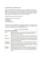
Figure 1-1: In Windows 95, you can select a port configuration in the Device
Manager's Resources Window. A message warns if Windows detects any system
conflicts with the selected configuration.
Select the desired printer model, then click
Connect
to view the available ports.
In
Windows 95, the Control Panel lists available ports under
System Properties,
Device Manager, Ports.
There's also a brief description of the port.
Printer Port
means that Windows treats the port as an ordinary SPP, while
ECP Printer Port
means that Windows will use the abilities of an ECP if possible. To change the
driver, select the port, then
Properties, Driver,
and Show
All Drivers.
Select the
driver and click
OK.
If an ECP doesn't have an IRQ and DMA channel, the Win-
dows 95 printer driver will use the ECP's Fast Centronics mode, which transfers
data faster than an SPP, but not as fast as ECP.
The Device Manager also shows the port's configuration. Select the port, then
click
Resources.
Figure 1-1 shows an example. Windows attempts to detect these
settings automatically. If the configuration shown doesn't match your hardware
setup, de-select the
Use Automatic Settings
check box and select a different con-
figuration. If none matches, you can change a setting by double-clicking on the
Parallel
Port
Complete
Essentials
resource type and entering a new value. Windows displays a message if it detects
any conflicts with the selected settings. To assign a printer to a port, click on Con-
trol Panel, Printers,
and select the printer to assign.
Parallel-port devices that don't use the Windows printer drivers should come with
their own configuration utilities. DOS programs generally have their own printer
drivers and methods for selecting a port as well.
Adding a Port
Most PCs come with one parallel port. If there's a spare expansion slot, it's easy
to add one or two more. Expansion cards with parallel ports are widely available.
Cards with support for bidirectional, EPP, and ECP modes are the best choice
unless you're sure that you won't need the new modes, or you want to spend as lit-
tle as possible. Cards with just an SPP are available for as little as $15. A card sal-
vaged from an old computer may cost you nothing at all.
You can get more use from a slot by buying a card with more than a parallel port.
Because the port circuits are quite simple, many multi-function cards include a
parallel port. Some have serial and game ports, while others combine a disk con-
troller or other circuits with the parallel port. On older systems, the parallel port is
on an expansion card with the video adapter. These should include a way to dis-
able the video adapter, so you can use the parallel port in any system.
When buying a multi-mode port, it's especially important to be sure the port
comes with utilities or documentation that shows you how to configure the port in
all of its modes. Some multi-mode ports default to an SPP configuration, where all
of the advanced modes are locked out. Before you can use the advanced modes,
you have to enable them. Because the configuration methods vary from port to
port, you need documentation.
Also, because the configuration procedures and other port details vary from chip
to chip, manufacturers of ECP and EPP devices may guarantee compatibility with
specific chips, computers, or expansion cards. If you're in the market for a new
parallel port or peripheral, it's worth trying to find out if the peripheral supports
using EPP or ECP mode with your port.
Port Hardware
The parallel port's hardware includes the back-panel connector and the circuits
and cabling between the connector and the system's expansion bus. The PC's
microprocessor uses the expansion bus's data, address, and control lines to trans-
Parallel Port Complete
9
Chapter 1
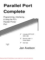
Figure 1-2: The photo on the left shows the back panel of an expansion card, with
a parallel port's 25-pin female D-sub connector on the left side of the panel. (The
other connector is for a video monitor.) The photo on the right shows the 36-pin
female Centronics connector used on most printers.
fer information between the parallel port and the CPU, memory, and other system
components.
Connectors
The PC's back panel has the connector for plugging in a cable to a printer or other
device with a parallel-port interface. Most parallel ports use the 25-contact D-sub
connector shown in Figure 1-2. The shell (the enclosure that surrounds the con-
tacts) is roughly in the shape of an upper-case D. Other names for this connector
are the subminiature D, DB25, D-shell, or just D connector. The IEEE 1284 stan-
dard for the parallel port calls it the IEEE 1284-A connector.
Newer parallel ports may use the new, compact, 36-contact IEEE 1284-C connec-
tor described in Chapter 6.
The connector on the computer is female, where the individual contacts are sock-
ets, or receptacles. The cable has a mating male connector, whose contacts are
pins, or plugs.
The parallel-port connector is usually the only female 25-pin D-sub on the back
panel, so there should be little confusion with other connectors. Some serial ports
use a 25-contact D-sub, but with few exceptions, a 25-pin serial D-sub on a PC is
male, with the female connector on the cable-the reverse of the parallel-port
convention. (Other serial ports use 9-pin D-subs instead.)
SCSI is another interface whose connector might occasionally be confused with
the parallel port's. The SCSI interface used by disk drives, scanners, and other
devices usually has a 50-contact connector, but some SCSI devices use a 25-con-
tact D-sub that is identical to the parallel-port's connector.
If you're unsure about which is the parallel-port connector, check your system
documentation. When all else fails, opening up the enclosure and tracing the cable
from the connector to an expansion board may offer clues.
1
0
Parallel Port Complete
The Circuits Inside
Cables
Essentials
Inside the computer, the parallel-port circuits may be on the motherboard or on a
card that plugs into the expansion bus.
The motherboard is the main circuit board that holds the computer's microproces-
sor chip as well as other circuits and slots for expansion cards. Because just about
all computers have a parallel port, the port circuits are often right on the mother-
board, freeing the expansion slot for other uses. Notebook and laptop computers
don't have expansion slots, so the port circuits in these computers must reside on
the system's main circuit board.
The port circuits connect to address, data, and control lines on the expansion bus,
and these in turn interface to the microprocessor and other system components.
Most printer cables have a 25-pin male D-sub connector on one end and a male
36-contact connector on the other. Many refer to the 36-contact connector as the
Centronics connector, because it's the same type formerly used on Centronics
printers.
Other names are parallel-interface connector or just printer connector.
IEEE 1284 calls it the 1284-B connector.
Peripherals other than printers may use different connectors and require different
cables. Some use a 25-pin D-sub like the one on the PC. A device that uses only a
few of the port's signals may use a telephone connector, either a 4-wire RJI I or
an 8-wire RJ45. Newer peripherals may have the 36-contact 1284-C connector.
In any case, because the parallel-port's outputs aren't designed for transmitting
over long distances, it's best to keep the cable short: 6 to 10 feet, or 33 feet for an
IEEE-1284-compliant cable. Chapter 6 has more on cable choices.
Multiple Uses for One Port
If you have more than one parallel-port peripheral, the easiest solution is to add a
port for each. But there may be times when multiple ports aren't an option. In this
case, the alternatives are to swap cables as needed, use a switch box, or
daisy-chain multiple devices to one port.
If you use only one device at a time and switch only occasionally, it's easy enough
to move the cable when you want to use a different device.
For frequent swapping, a more convenient solution is a switch box. A typical
manual switch box has three female D-sub connectors. A switch enables you route
Parallel Port Complete
1
1
Chapter 1
the contacts of one connector to either of the others. To use the switch box to
access two peripherals on one port, you'll need a cable with two male D-subs to
connect the PC to the switch box, plus an appropriate cable from the switch box to
each peripheral.
You can also use a switch box to enable two PCs to share one printer or other
peripheral. This requires two cables with two male D-subs on each, and one
peripheral cable. Switch boxes with many other connector types are also avail-
able.
Manual switches are inexpensive, though some printer manufacturers warn that
using them may damage the devices they connect to. A safer choice is a switch
that uses active electronic circuits to route the signals. Some auto-sensing
switches enable you to connect multiple computers to one printer, with first-come,
first-served access.
When a printer is idle, any computer can access it. When the
printer is in use, the switch prevents the other computers from accessing it. How-
ever, these switches may not work properly if the peripherals use bidirectional
communications, or if the peripheral uses the control or status signals in an uncon-
ventional way.
The parallel ports on some newer peripherals support a daisy-chain protocol that
allows up to eight devices to connect to a single port. The PC assigns a unique
address to each peripheral, which then ignores communications intended for the
other devices in the chain. The software drivers for these devices must use the
protocol
when they access the port. The last device in the chain can be
daisy-chain-unaware; it doesn't have to support the protocol. Chapter 11 has more
on daisy chains.
Security Keys
Security keys, or dongles, are a form of copy protection that often uses the parallel
port. Some software-usually expensive, specialized applications-includes a
security key that you must plug into the parallel port in order to run the software.
If you don't have the key installed, the software won't run.
The key is a small device with a male D-sub connector on one end and a female
D-sub on the other. You plug the key into the parallel-port connector, then plug
your regular cable into the security key. When the software runs, it attempts to
find and communicate with the key, which contains a code that the software rec-
ognizes. The key usually doesn't use any conventional handshaking signals, so it
should be able to live in harmony with other devices connected to the port.
1
2
Parallel Port Complete
The keys do require power, however. If you have a key that draws more than a
small amount of current, and if your parallel port has weak outputs, you may have
problems in using other devices on the same port as the key.
Alternatives to the Parallel Port
The parallel port is just one of many ways to interface inputs and outputs to a
computer. In spite of its many virtues, the parallel port isn't the best solution for
every project. These are some of the alternatives:
Serial Interfaces
Parallel Port Complete
Essentials
One large group of parallel-port alternatives is serial interfaces, where data bits
travel on a single wire or pair of wires (or in the case of wireless links, a single
transmission path.) Both ends of the link require hardware or software to translate
between serial and parallel data. There are many types of serial interfaces avail-
able for PCs, ranging from the ubiquitous RS-232 port to the newer RS-485, USB,
IEEE-1394, and IrDA interfaces.
RS-232
Just about every PC has at least one RS-232 serial port. This interface is especially
useful when the PC and the circuits that you want to connect are physically far
apart.
As a rule, parallel-port cables should be no longer than 10 to 15 feet, though the
IEEE-1284 standard describes an improved interface and cable that can be 10
meters (33 feet). In contrast, RS-232 links can be 80 feet or more, with the exact
li
mit depending on the cable specifications and the speed of data transfers.
RS-232 links are slow, however. Along with each byte, the transmitting device
normally adds a start and stop bit. Even at 115,200 bits per second, which is a typ-
ical
maximum rate for a serial port, the data-transfer rate with one start and stop
bit per byte is just 11,520 bytes per second.
RS-485
Another useful serial interface is RS-485, which can use cables as long as 4000
feet and allows up to 32 devices to connect to a single pair of wires. You can add
an expansion card that contains an RS-485 port, or add external circuits that con-
vert an existing RS-232 interface to RS-485. Other interfaces similar to RS-232
and RS-485 are RS-422 and RS-423.
1
3
Chapter 1
Universal Serial Bus
A new option for I/O interfacing is the Universal Serial Bus (USB), a project of a
group that includes Intel and Microsoft. A single USB port can have up to 127
devices communicating at either 1.5 Megabits/second or 12 Megabits/second over
a 4-wire cable. The USB standard also describes both the hardware interface and
software protocols. Newer PCs may have a USB port built-in, but because it's so
new, most existing computers can't use it without added hardware and software
drivers.
I
EEE 1394
The IEEE-1394 high-performance serial bus, also known as Firewire, is another
new interface. It allows up to 63 devices to connect to a PC, with transmission
rates of up to 400 Megabits per second. The 6-wire cables can be as long as 15
feet, with daisy chains extending to over 200 feet. The interface is especially pop-
ular for connecting digital audio and video devices. IEEE-1394 expansion cards
are available for PCs.
IrDA
The IrDA (Infrared Data Association) interface allows wireless serial communica-
tions over distances of 3 to 6 feet. The link transmits infrared energy at up to
115,200 bits/second. It's intended for convenient (no cables or connectors) trans-
mitting of files between a desktop and laptop computer, or any short-range com-
munications where a cabled interface is inconvenient. Some computers and
peripherals now have IrDA interfaces built-in.
Other Parallel Interfaces
SCSI and IEEE-488 are two other parallel interfaces used by some PCs.
SCSI
SCSI (small computer system interface) is a parallel interface that allows up to
seven devices to connect to a PC along a single cable, with each device having a
unique address. Many computers use SCSI for interfacing to internal or external
hard drives, tape back-ups, and CD-ROMs. SCSI interfaces are fast, and the cable
can be as long as 19 feet (6 meters). But the parallel-port interface is simpler,
cheaper, and much more common.
I
EEE 488
The IEEE-488 interface began as Hewlett Packard's GPIB (general-purpose inter-
face bus). It's a parallel interface that enables up to 15 devices to communicate at
1
4
Parallel Port Complete