WASTE WATER TREATMENT SYSTEM DESCRIPTION THUYẾT MINH HỆ THỐNG XỬ LÝ NƯỚC THẢI
Bạn đang xem bản rút gọn của tài liệu. Xem và tải ngay bản đầy đủ của tài liệu tại đây (658.33 KB, 35 trang )
FOR CONSTRUCTION
0INT1
0
Rev
Owner
30.06.2020
H.J.KIM
Y.H.PARK
S.K.LEE
21.10.2019
H.J.KIM
Y.H.PARK
S.K.LEE
FOR CONSTRUCTION
FOR CONSTRUCTION
Date
Prepared
Checked
Approved
Details of Revision
Owner’s Engineer
Contractor
DOOSAN HEAVY INDUSTRIES & CONSTRUCTION
Sub-Supplier
CHUNG-AM WATER TREATMENT & ENGINEERING CO., LTD.
Project
NGHI SON 2 BOT THERMAL POWER PLANT PROJECT (2×600MW)
Title
SYSTEM DESCRIPTION FOR WASTE WATER TREATMENT PLANT
Document No.
Rev.
NS2-XS00-P0GN-120001
0INT1
Page-No.
34
SYSTEM DESCRIPTION
NS2-XS00-P0GN-120001
RECORD OF REVISION
Rev.
Date
Page Affected
Description of Revision
0
21.10.2019
33
For Construction
0INT1
30.06.2020
34
For Construction
Rev.0INT1
1 of 34
SYSTEM DESCRIPTION
NS2-XS00-P0GN-120001
Table of Contents
No.
Description
Page
1.
Introduction
3
2.
System / Component Description
3
2.1
Main Equipment
4
2.2
Flow Diagram
10
2.2.1
Oily Water Treatment Plant
10
2.2.2
Industrial Waste Water Treatment Plant
11
2.3
Industrial Waste Water Treatment Process
12
2.4
Equipment Description
13
Chemicals Handling for Waste Water Treatment Plant
17
3.1
Filling of Chemical Storage Tank
17
3.2
Responsibilities and Duties during Chemical Filling
18
4.
Control
19
5.
Code & Standard
20
6.
References & Abbreviation
22
7
Operation Philosophy for Waste Water Treatment
23
3.
Rev.0INT1
2 of 34
SYSTEM DESCRIPTION
NS2-XS00-P0GN-120001
1. INTRODUCTION
This system description is prepared to understand the process & equipment for waste water
treatment plant in Nghi Son 2 Thermal Power Plant Project in Vietnam.
Waste water treatment plant of Nghi Son 2 Thermal Power Plant is consisting of following major
sources of waste water streams.
2. SYSTEM / COMPONENT DESCRIPTION
Normal waste water :
•
Demi Water Plant
•
Chemical Dosing System
•
Sampling System
Abnormal waste water:
•
Boiler Chemicla Cleaning(Rinse)
•
EP Washing Water
•
AH Washing Water
•
Blowdown Quenching Water
•
SCR Waste Water
•
CPP Waste Water
•
Electro Chlorination Plant
•
Plant Area Sump
•
Coal Run-off Pond
•
Ash Waste Water
Oily waste water:
•
Unit#1 Turbine building oily sump
•
Unit#2 Turbine building oily sump
•
Unit#1 Transformer area oily sump
•
Unit#2 Transformer area oily sump
•
Fire Fighting Pump House Area Sump
•
Aux Boiler Area Oily Sump
•
Unit#1 Boiler area oily sump
•
Unit#2 Boiler area oily sump
•
Fly ash transfer compresser shelter oily sump
•
LDO area Oily Sump
•
Workshop & Wareahouse area oily sump
•
Vehicle repair shop area oily sump
The purpose of waste water treatment plant is to collect normal, abnormal and oily waste water
generated in the power plant, treat them and then dispose as per requirement.
Rev.0INT1
3 of 34
SYSTEM DESCRIPTION
NS2-XS00-P0GN-120001
2.1 MAIN EQUIPEMNT
Specification
Denomination
Industrial waste water treatment system
Normal Waste Water Pond
(P0GNK01BB001)
Normal Waste Water Feed Pump
A/B (P0GNK02/03AP001)
Abnormal Waste Water Pond
(P0GNK05BB001)
AIR-BLOWER(COMMON)
(P0GNC11/12/13AN001)
Abnormal Waste Water Feed
Pump
(P0GNK05/06/07AP001)
pH Adjustment Pond
(P0GNK08BB001)
Agitator for pH Adjustment Pond
(P0GNK08AM001)
Coagulation Pond
(P0GNK08BB002)
Agitator for Coagulation Pond
(P0GNK08AM002)
Flocculation Pond
(P0GNK08BB003)
Agitator for Flocculation Pond
(P0GNK08AM003)
Clarifier (P0GNS01BB001)
- Quantity
- Dimension
- Effective Depth
- Retention Time
- Material
- Quantity
- Type
- Capacity
- Head
- Quantity
- Dimension
- Effective Depth
- Retention Time
- Material
- Quantity
- Type
- Capacity
- Head
- Quantity
- Type
- Capacity
- Head
- Quantity
- Dimension
- Effective Depth
- Retention Time
- Material
One (1×100%)
41mL x 12mW x 4mH
3.5mH
8hr
RCC + Painting
Two (2 ×100%)
Horizontal & Centrifugal
180m3/hr
15m
One (1×100%)
41mL x 34.5mW x 4mH
3.5mH
50hr
RCC + Painting
Three (3 ×50%)
Twin lobe (Roots)
35Nm3/min
4m
Three (3×50%)
Horizontal & Centrifugal
80m3/hr
15m
One (1×100%)
6.0mL x 4.0mW x 3.0mH
2.5mH
20min
RCC + Painting
- Quantity
- Type (Impeller)
- Speed
- Material (Impeller)
- Quantity
- Dimension
- Effective Depth
- Retention Time
- Material
- Quantity
- Type (Impeller)
- Speed
- Material (Impeller)
- Quantity
- Dimension
- Effective Depth
- Retention Time
- Material
- Quantity
- Type (Impeller)
- Speed
- Material (Impeller)
- Quantity
- Dimension
- Effective Depth
- Retention Time
One (1×100%)
Propeller / 2stage
153RPM
CS + R/L
Rev.0INT1
One (1×100%)
3.0mL x 4.0mW x 3.0mH
2.5mH
10min
RCC + Painting
One (1×100%)
Propeller / 2stage
153RPM
STS316
One (1×100%)
6.0mL x 4.0mW x 3.0mH
2.5mH
20min
RCC + Painting
One (1×100%)
Propeller/ 2stage
51RPM
STS316
One (1×100%)
17.0mΦ x 3.8mH
3.3mH
4hr
4 of 34
SYSTEM DESCRIPTION
NS2-XS00-P0GN-120001
Specification
Denomination
Clarifier Scraper
(P0GNS01AM001)
- Material
RCC + Painting
- Quantity
- Type (Motor/Reducer)
- Speed
- Material
- Quantity
- Type
- Capacity
- Head
- Quantity
- Dimension
- Effective Depth
- Retention Time
- Material
- Quantity
- Type
- Capacity
- Head
- Quantity
- Type
- Capacity
- Head
Dual Medial Filter (DMF) A/B
(P0GNK13/14BB001)
- Quantity
- Dimension
- Type
- Linear Velocity
- Material
Activated Carbon Filter (ACF) A/B
(P0GNK15/16BB001)
- Quantity
- Dimension
- Type
- Linear Velocity
- Material
One (1×100%)
Vertical / Cycloid
0.038RPM
SS400 + Painting
Two (2 ×100%)
Horizontal & Centrifugal
19m3/hr
20m
One (1×100%)
7.65mL x 7.65mW x 4.0mH
3.5mH
1hr
RCC + Painting
Two (2 ×100%)
Horizontal & Centrifugal
180m3/hr
30m
Two (2 ×100%)
Twin lobe (Roots)
8Nm3/min
4m
Two (2 ×100%)
3.4mΦ x 1.83mH
Vertical & Cylindrical
20㎥/㎡/hr
A516-70 + Epoxy painting
Two (2 ×100%)
3.4mΦ x 2.4mH
Vertical & Cylindrical
20㎥/㎡/hr
A516-70 + Epoxy painting
Final pH Adjustment Pond
(P0GNK20BB001)
- Quantity
- Dimension
- Effective Depth
- Retention Time
- Material
One (1×100%)
7.65mL x 4.0mW x 2.5mH
2mH
15min
RCC + Painting
Agitator for Final pH
Adjustment Pond
(P0GNK20AM001)
- Quantity
- Type (Impeller)
- Speed
- Material (Impeller)
- Quantity
- Dimension
- Effective Depth
- Retention Time
- Material
- Quantity
- Type
- Capacity
- Head
One (1×100%)
Propeller / 2stage
106RPM
A240-304
One (1×100%)
7.65mL x 13.5mW x 4.0mH
3.5mH
2hr
RCC + Painting
Two (2 ×100%)
Horizontal & Centrifugal
330m3/hr
20m
Two (2 ×100%)
Horizontal & Centrifugal
180m3/hr
40m
Sludge Transfer Pump A/B
(P0GNS02/03AP001)
Clarified Water Pond
(P0GNK10BB001)
Clarified Water Pump A/B
(P0GNK11/12AP001)
Air Blower A/B for DMF
(P0GNC01/02AN001)
Final Effluent Pond
(P0GNK20BB002)
Final Backwash Pump A/B
(P0GNK25/26AP001)
Final Effluent Pump A/B
(P0GNK22/23AP001)
- Quantity
- Type
- Capacity
- Head
Rev.0INT1
5 of 34
SYSTEM DESCRIPTION
NS2-XS00-P0GN-120001
Specification
Denomination
Sludge Thickener
(P0GNS05BB001)
- Quantity
- Dimension
- Effective Depth
- Retention Time
- Material
Sludge Thickener Scraper
(P0GNS05AM001)
- Quantity
- Type (Motor/Reducer)
- Speed
- Material
Thickened Sludge Transfer Pump
A/B (P0GNS06/07AP001)
- Quantity
- Type
- Capacity
- Head
- Quantity
- Dimension
- Effective Depth
- Retention Time
- Material
- Quantity
- Type (Impeller)
- Speed
- Material (Impeller)
- Quantity
- Type
- Capacity
- Head
- Quantity
- Dimension
- Effective Capacity
- Material
- Accessories
Sludge Mixing Tank
(P0GNS08BB001)
Agitator for Sludge Mixing Tank
(P0GNS08AM001)
Sludge Lift Pump
(P0GNS10AP001/002)
Filter Press (P0GNS10AT001)
Caustic Storage Tank
(P0GNN01BB001)
Cuastic Unloading & Transfer
Pump A/B
(P0GNN02/03AP001)
Caustic Dosing Tank
(P0GNN05BB001)
Caustic Dosing Pump A/B
(For pH Adjustment Pond)
(P0GNN06/07AP001)
Caustic Dosing Pump A/B
(For Final pH Adjustment Pond)
(P0GNN08/09AP001)
Agitator for Caustic Dosing Tank
(P0GNN05AM001)
- Quantity
- Dimension
- Type
- Material
- Quantity
- Type
- Capacity
- Head
- Quantity
- Dimension
- Type
- Retention Time
- Material
- Quantity
- Type
- Capacity
- Head
- Quantity
- Type
- Capacity
- Head
- Quantity
- Type (Motor/Impeller)
- Speed
- Material (Impeller)
Rev.0INT1
One (1×100%)
5.0mΦ x 3.8mH
3.3mH
4.5hr
RCC + Painting
One (1×100%)
Vertical / Cycloid
0.13 RPM
SS400 + Painting
Two (2 ×100%)
Horizontal & Centrifugal
19m3/hr
20m
One (1×100%)
1.6mΦ x 2mH
1.8mH
25min
SS400 + Epoxy painting
One (1×100%)
Propeller / 2stage
153RPM
A240-304
Two (2 ×100%)
Diaphragm
340L/min
5bar
One (1×100%)
7.0mL x 1.8mW x 2.7mH
2.8 m3/hr
A36 + Epoxy Painting
Cake Hopper 1set
Control Panel 1set
One (1×100%)
2.4mΦ x 2.5mH
Cylindrical
A240 - 304
Two (2 ×100%)
Horizontal & Centrifugal
2m3
12m
One (1×100%)
1.4mΦ x 1.6mH
Cylindrical
48hr
A240-304
Two (2×100%)
Diaphragm
70ℓ/hr
20m
Two (2×100%)
Diaphragm
70ℓ/hr
20m
One (1×100%)
Propeller / 2stage
150RPM
A240-304
6 of 34
SYSTEM DESCRIPTION
NS2-XS00-P0GN-120001
Specification
Denomination
Acid Storage Tank A/B
(P0GNN11BB001)
- Quantity
- Dimension
- Type
- Material
- Quantity
- Type
- Capacity
- Head
- Quantity
- Dimension
- Type
- Retention Time
- Material
- Quantity
- Type
- Capacity
- Head
- Quantity
- Type
- Capacity
- Head
- Quantity
- Type (Motor/Impeller)
- Speed
- Material (Impeller)
- Quantity
- Dimension
- Type
- Material
- Quantity
- Type
- Capacity
- Head
- Quantity
- Dimension
- Type
- Retention Time
- Material
- Quantity
- Type
- Capacity
- Head
- Quantity
- Type (Impeller)
- Speed
- Material (Impeller)
Two (2×100%)
2.4mΦ x 2.5mH
Cylindrical
SS400 + Rubber Lining
Two (2×100%)
Horizontal & Centrifugal
2m3
12m
One (1×100%)
1.4mΦ x 1.6mH
Cylindrical
48hr
SS400 + Rubber Lining
Two (2×100%)
Diaphragm
70ℓ/hr
20m
Two (2×100%)
Diaphragm
70ℓ/hr
20m
One (1×100%)
Propeller / 2stage
150RPM
SS400 + Rubber Lining
One (1×100%)
2.4mΦ x4.7mH
Cylindrical
A240-304
Two (2×100%)
Horizontal & Centrifugal
5m3/hr
12m
One (1×100%)
1.4mΦ x 1.6mH
Cylindrical
72hr
A240-304
Two (2×100%)
Diaphragm
122ℓ/hr
20m
One (1×100%)
Propeller / 2stage
150RPM
A240-304
A-Polymer Auto Dissolving Unit
(P0GNN21BB001)
- Quantity
- Type
- Size
One (1×100%)
3-Stage Tank
1.84mL x 0.75mW x0.75mH
A-Polymer Dosing Pump A/B
(P0GNN22/23AP001)
- Quantity
- Type
- Capacity
- Head
- Quantity
- Type
- Size
- Material
Two (2×100%)
Diaphragm
360ℓ/hr
20m
One (1×100%)
Vertical
0.45mΦ x 0.75mH
FRP
Acid Unloading & Transfer Pump
A/B (P0GNN12/13AP001)
Acid Dosing Tank
(P0GNN15BB001)
Acid Dosing Pump A/B
(For pH Adjustment Pond)
(P0GNN16/17AP001)
Acid Dosing Pump A/B
(For Final pH Adjustment Pond)
(P0GNN18/19AP001)
Agitator for Acid Dosing Tank
(P0GNN15AM001)
Coagulant Storage Tank
(P0GNN25BB001)
Coagulant Transfer Pump A/B
(P0GNN26/27AP001)
Coagulant Dosing Tank
(P0GNN28BB001)
Coagulant Dosing Pump A/B
(P0GNN29/30AP001)
Agitator for Coagulant
Dosing Tank (P0GNN28AM001)
Fume Absorber
(P0GNN14BB001)
Rev.0INT1
7 of 34
SYSTEM DESCRIPTION
NS2-XS00-P0GN-120001
Specification
Denomination
Drum Pump A/B
(P0GNN31/32AP001)
Sump Pump A/B for Drain Pit
(P0GNN34/35AP001)
Pump Room Drain Pit
(P0GNN33BB001)
Air Receiver Tank for Instrument
Air (P0GNB11BB001)
Air Receiver Tank for Service Air
(P0GNC05BB001)
Eye washer & Safety shower
(P0GNK26AZ001/002/003/004)
WWT Retention Pond
(P0GNK30BB001)
WWT Transfer Pump A/B for
WWT Retention Pond
(P0GNK30/31AP001)
- Quantity
- Type
- Capacity
- Head
- Quantity
- Type
- Capacity
- Head
- Quantity
- Dimension
- Effective Depth
- Retention Time
- Material
- Quantity
- Type
- Capacity
- Size
- Material
- Quantity
- Type
- Capacity
- Size
- Material
- Quantity
- Type
Two (2×100%)
Drum Pump
5m3/hr
18m
Two (2×100%)
Drum Pump
20m3/hr
15m
One (1×100%)
2.0mL x 1.4mW x 2.0mH
1.8mH
1hr
RCC + Painting
One (1×100%)
Vertical & Cylindrical
0.28m3
0.55mΦ x 1.2mH
A240 Gr 304
One (1×100%)
Vertical & Cylindrical
0.28m3
0.55mΦ x 1.2mH
A240 Gr 304
Four (4×100%)
Hand & Foot Control
- Quantity
- Dimension
- Effective Depth
- Retention Time
- Material
- Quantity
- Type
- Capacity
- Head
One (1×100%)
65mL x 35mW x 4.1mH
3.5mH
2 day
RCC + Painting
Two (2 ×100%)
Horizontal Self-Priming
180m3/hr
30m
- Quantity
- Dimension
- Effective Depth
- Retention Time
- Material
- Quantity
- Size
- Type
- Capacity
- Material
One (1×100%)
6.35mL x 16.0mW x 4.0mH
3.5mH
12hr
RCC + Painting
Two (2×100%)
0.55mL x 0.4mW x 0.65mH
Belt
90l/hr x 2set
A240TP304 / A283Gr.C,
A194 Gr2H
Two (2×100%)
Horizontal & Centrifugal
25m3/hr
15m
Two (2×100%)
5.12mL x1.72mW x1.9mH
EPS
25m3/hr
SS400 + Epoxy painting
0INT1
Oily waste water treatment system
Oily Waste Water Pond
(P0GNB01BB001)
Oil Skimmer A/B
(P0GNB01/02AT001)
Oily Waste Water Feed Pump A/B
(P0GNB04/05AP001)
Oil Separator
(P0GNB05/06AT001)
- Quantity
- Type
- Capacity
- Head
- Quantity
- Size
- Type
- Capacity
- Material
Rev.0INT1
8 of 34
SYSTEM DESCRIPTION
NS2-XS00-P0GN-120001
Specification
Denomination
Oil Sludge Pond
(P0GNB10BB001)
- Quantity
- Dimension
- Effective Depth
- Material
One (1×100%)
2.0mL x 2.5mW x 1.2mH
1.0mH
RCC + Painting
Oil Sludge & Skimmed Oil Pump
(P0GNB10AP001/002)
- Quantity
- Type
- Capacity
- Head
Two (2×100%)
Diaphragm
10m3/hr
20m
Rev.0INT1
9 of 34
SYSTEM DESCRIPTION
NS2-XS00-P0GN-120001
2.2 FLOW DIAGRAM
2.2.1 OILY WASTE WATER TREATMENT PLANT
Oily Waste Water
Oily Waste Water Pond
Oil Skimmer
Oil Slurry
Oil Separator
Oil Slurry
Normal Waste Water Pond
Oil Sludge Pond
To Tank Lorry
Rev.0INT1
10 of 34
SYSTEM DESCRIPTION
NS2-XS00-P0GN-120001
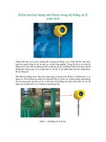
2.2.2 INDUSTRIAL WASTE WATER TREATMENT PLANT
Abnormal Waste Water
Normal Waste Water
Abnormal Waste Water Pond
Air
Blower
Normal Waste Water Pond
HCl
NaOH
pH Adjustment Pond
Coagulant
Coagulation Pond
Polymer
Flocculation Pond
Air
Blower
Sludge
Clarifier
Clarified Water Pond
HCl
NaOH
Dual Media Filter A/B
Sludge Thickener
Activated Carbon Filter A/B
Filter press / Cake Hopper
Sludge
cake
Air/
Water for
backwash
Final pH Adjustment Pond
To Truck
Final Effluent Pond
0INT1
WWT Retention Pond
Reuse or CW Discharge canal
Rev.0INT1
11 of 34
SYSTEM DESCRIPTION
NS2-XS00-P0GN-120001
2.3 INDUSTRIAL WASTE WATER TREATMENT PROCESS
In this section a detailed description of duty of all major units will be provided. Whole of the
waste water treatment plant is divided into two major sub categories
•
Industrial Waste Water Treatment Process
•
Oily Waste Water Treatment Process
2.3.1
INDUSTRIAL WASTE WATER TREATMENT PROCESS
- Equalization
The equalized waste water being transferred from the normal waste water pond will be first pH
corrected in a pH adjustment pond by dosing acid (15% HCl), caustic (15% NaOH) depending
on the incoming pH.
- Coagulation and Flocculation
The pH corrected waste water will gravitate to the downstream coagulation pond, flocculation
pond and clarifier. Coagulant 10% (Alum) will be dosed in the coagulation pond for cohesion
the particles in the waste water whereas A-polymer will be dosed in the flocculation pond for
enlarging floc. formation.
- Clarification and Filteration
The flocs would then be settled in the downstream conventional clarifier. And clarified water
will be transferred to clarified water pond. The clarified water transferred and treated in the
dual media filter & activated carbon filter. Finally the filtered water will be transferred to the final
pH adjustment pond. If the Backwash process,Treated waste water is backwashed in Dual
Media Filter (DMF) & Activated Carbon Filter (ACF) by the filter backwash pump.
The backwash water from DMF & ACF will be transferred to normal waste water sump.
- Discharge and Monitoring
The treated waste water will be transfer to Final Effluent Pond and will be discharged into CW
discharge canal or Reuse(Dust Suppression System(CHS), Make Up Water Pond(AHS))..
Before discharge, flow and pH value will be monitored. And also The waste water monitoring
system located before CW discharge canal will be monitored the environment parameters (pH,
COD and TSS) and then DCS will be send the signal to WWT.
- Sludge Treatment
The sludge from the clarifier will be periodically transferred to a sludge thickener via sludge
transfer pump. Overflowed water from the sludge thickener is again treated to the normal
waste water pond. The thickened sludge from the sludge thickener will be dewatered in a filter
press.
The filtered water from filter press will be transferred to the normal waste water pond.
The sludge cake generated from the cake hopper can be disposed of by truck.
Note: 15% HCl, 15% NaOH and 8% (Alum), 0.2% A-Polymer will be applied for this project.
2.3.2
OILY WASTE WATER TREATMENT PROCESS
Oily waste water pond is used to collect oily waste water from turbine area drains, boiler area
drains, transformer area drains and drains other oil contaminated area of the plant. Remove oil
from the oil skimmer first. And then from the oily waste water pond, oily waste water is
transferred to the oil simmer and oil separator, where oil and water must be separated.
The separated water from the oil separator is transferred to the normal waste water pond.
The separated oil and oil sludge of the sludge chamber are collected in the oil sludge pond by
gravity. The oil sludge are disposed of tank lorry by a tank truck own pump.
The flushing water which washed plate by service water will return to oily waste water pond.
All piping associated with the oily waste water treatment system will be oil resistant pipe. Oil
Rev.0INT1
12 of 34
SYSTEM DESCRIPTION
NS2-XS00-P0GN-120001
sludge pump and skimmed oil pump & supplied flexible hose will be used if a pump & hose of
tank lorry is not possible to use.
2.4 EQUIPMENT DESCRIPTION
2.4.1 Normal Waste Water Pond
Industrial waste water (MBP regeneration waste water, Sampling system) from the various
process on the power plant site will be collected and transferred to the normal waste water
pond.
Air-Blower(Conmmon) will keep liquid to prevent settling of suspended solid inside the pond.
The contents of the normal waste water pond will be aerated. Two (2) normal waste water feed
pumps will transfer the contents of the normal waste water pond to the clarifier.
2.4.2 Abnormal Waste Water Pond
Abnormal waste water (CPP regeneration waste water, Boiler chemical cleaning waste, Boiler
blowdown quenching water, Cleaning water for ESP, Cleaning water for air heater, Coal runoff
pond, Electro chlorination plant, Ash handling system) is generated at abnormal intervals in the
plant like blow down water etc. will be stored in the Abnormal waste water pond. Coal and ash
contaminated waste water after settling is transferred to abnormal waste water pond heavy rain
season.
Air-Blower(Conmmon) will be used to prevent contents of abnormal waste water pond from
settling inside the pond. Three (3) abnormal waste water feed pumps will transfer the contents
of the abnormal waste water pond to normal waste water pond which will be treated in the
waste water treatment system.
In case of normal, the one(1) abnormal waste water pump operates. If it is abnormal, two(2)
operate at the same time.
2.4.3 pH Adjustment Pond
pH of the waste water from the normal waste water pond will be adjusted in the pH adjustment
pond for reacting coagulation and flocculation efficiently. Provision is made to dose acid and
caustic to this unit. One agitator will be used to mix the contents of the pH adjustment pond.
2.4.4 Coagulation Pond
pH corrected waste water is moved to the coagulation pond where the lighter particle coagulate
by overflows from pH adjustment pond. Alum is added to the coagulation pond from the
coagulant dosing system. Two (2) coagulant dosing pumps will transfer coagulant from the
coagulant doing system to coagulation pond. 1 No. agitator will be used to mix the contents of
the coagulation pond.
The debris and dense material is removed by means of chemical cohesion.
Commonly Alum is used and the coagulation reaction of cohesion is as following.
Al2(SO4)3 ∙18 H2O + 3 Ca(HCO3)2 → 2Al(OH)3↓ + 3CaSO4 + 6CO2 + 18H2O
2.4.5 Flocculation Pond
In the Flocculation pond lighter colloidal particles are made in to dense floc with the help of
adding of Flocculant. Flocculant (Anionic Polymer) is added to the flocculation pond from the
Flocculant dosing system. Two (2) A-polymer dosing pumps will transfer Flocculant from the
Flocculant doing system to flocculation pond. One agitator will be used to mix the contents of
the flocculation pond.
2.4.6 Clarifier
Clarifier is provided to clarify the waste water. Under the effect of gravity dense particles are
settled at the bottom of the clarifier and passed to the sludge thickener by two (2) sludge
transfer pumps Clarified water from the clarifier will be overflowed to the clarified water pond.
Operator should find out optimized operation time by using sampling points installed on clarifier.
It has a cylindrical steel structure with conical bottom; central well, scraper arms at bottom and
a structural bridge.
The waste water enters the clarifier at central well and flows to bottom of clarifier. The waste
water of central well rise from bottom to clarifier periphery. While waste water rises to clarifier
top, the solid particles settle at bottom cone and top rising water overflows to the Clarified water
pond.
Rev.0INT1
13 of 34
SYSTEM DESCRIPTION
NS2-XS00-P0GN-120001
The scraper arm rotates at a low speed at the clarifier bottom. Due to the rotating movement of
the scraper arm the sludge collected at bottom of clarifier is moved to the central cone of
clarifier.
The sludge is about 1% consistency and it is periodically taken out by two (2) sludge transfer
pumps.
The clarifier will remove turbidity, color and organic matter from the influent water.
2.4.7
Clarified Water Pond
Clarified water from clarifier is stored in the clarified water pond. Two clarified water pumps will
feed clarified water to the dual media filter & activated carbon filter units.
2.4.8
Dual Media Filter
Dual media filter with sand and anthracite beds is provided to remove suspended solids and
turbidity present in clarified water.
Suspended matters and turbidity gets removed when clarified water is passed in downward
direction through this filter bed. The unit should be backwashed whenever the pressure drop
exceeds the preset value. An air scour system has been provided to loosen the media before
backwash for effective removal of settled solids. This comes in handy if the impurities on the
media bed are particularly difficult to breakup with a normal backwash.
2.4.9 Activated Carbon Filter
Activated carbon filter with sand & Activated carbon beds is provided to remove odor,
chromaticity.
Suspended matters and turbidity gets removed when clarified water is passed in downward
direction through this filter media.
2.4.10 Sludge Thickener
Sludge from clarifier will be transferred sludge thickener. Sludge is thickened under the effect
of gravity in the sludge thickener. A slow moving sludge thickener scraper will be operated in
the sludge thickening process. Overflowed water from the sludge thickener is transferred to
the normal waste water pond.
It has a cylindrical steel structure with conical bottom; central well, scraper arms at bottom and
a structural bridge.
Sludge thickener works on similar principle of clarifier. The sludge enters the thickener at
central well and flows to bottom of thickener. The thickened sludge comes out of central well
from bottom and rises to thickener periphery. While sludge rises to thickener top, the solid
particles settle at bottom cone and top rising water overflows to the normal waste water pond.
The scraper arm rotate with a low speed at the thickener bottom. Due to the rotating
movement of the scraper arm, the sludge collected at bottom of thickener is moved to the
central cone of thickener.
The sludge is about 2% consistency and it is periodically taken out by thickened sludge
transfer pumps.
2.4.11 Sludge Mixing Tank
Thickened sludge collected at the bottom of the sludge thickener is transferred to the sludge
mixing tank by two (2) thickened sludge transfer pumps.
2.4.12 Filter press
Filter press is a sludge dewatering device that applies mechanical pressure and operation
mode is one batch type.
One batch type process is as followings:
First, the filter press oil cylinder is moved to press the filter plate.
From sludge mixing tank, conditioned sludge is fed to filter press by sludge lift pump.
The sludge is trapped between filter plates and is passed through a filter clothes.
Due to the pressure applied, the water is squeezed out of the sludge.
When the operation time is over by the timer, the operator transfers the filter plate and drops
the solid sludge between the filter plates to the cake hopper.
Rev.0INT1
14 of 34
SYSTEM DESCRIPTION
NS2-XS00-P0GN-120001
Filter press receives sludge of about 2% consistency (from sludge mixing tank) and produces
sludge cake of 20% consistency.
Sludge discharged in the cake hoper will be taken out periodically to the disposal.
The sludge cake is stored in the cake hopper and periodically disposed by owner using the
truck.
2.4.13 Final pH Adjustment Pond
Before final discharge, the pH of the treated waste water has to be adjusted as per pH value.
If the pH value does not meet the criteria, Acid and caustic will be dosed in this unit by dosing
pumps.
2.4.14 Final Effluent Pond
Treated waste water is stored in the final effluent pond. Two (2) effluent pumps will be used to
dispose the treated waste water.
Normal Case : Reuse for CHS dust suppression
If coal runoff pond full, this case treated water flow to CW discharge canal.
Note : Discharge through Waste water monitoring system before going to sea.
2.4.15 Chemical Dosing System
The waste water treatment plant uses chemicals comprising of caustic soda, acid, alum and
solid polymer (A-polymer).
2.4.15.1 Caustic Dosing System
The purpose of caustic dosing system is controlling pH value of pH adjustment pond and
final pH adjustment pond.
Cuastic System comprises of the following equipment:
- Caustic Storage Tank : 1 x 100%
- Caustic Dosing Tank : 1 x 100%
- Caustic Dosing Pump for pH adjustment pond : 2 x 100%
- Caustic Dosing Pump for final pH adjustment pond : 2 x 100%
Cuastic (45%, NaOH) is stored in Cuastic storage tank. It is charged by tank lorry or drum.
Cuastic (45%, NaOH) are transferred and is diluted to 15% caustic solution in caustic
dosing tank
Diluted Cuastic (15%, NaOH) is used to wastewater treatment system
2.4.15.2
Acid Dosing System
The purpose of acid dosing system is controlling pH value of pH adjustment pond and final
pH adjustment pond.
Acid System comprises of the following equipment:
- Acid Storage Tank : 2 x 100%
- Acid Dosing Tank : 1 x 100%
- Fume Absorber : 1 x 100%
- Acid Dosing Pump for pH adjustment pond : 2 x 100%
- Acid Dosing Pump for final pH adjustment pond : 2 x 100%
Acid(35%, HCl) is stored in acid storage tank. It is charged by tank lorry or drum.
Acid (35%, HCl) are transferred and is diluted to 15% acid solution in acid dosing tank
Diluted acid (15%, HCl) is used to wastewater treatment system
2.4.15.3
Coagulant Dosing System
Alum shall be used as the coagulant.
Purpose of coagulant dosing system is to coagulate suspended solid in water.
Coagulant System comprises of the following equipment:
- Coagulant Storage Tank : 1 x 100%
- Coagulant Dosing Tank : 1 x 100%
- Coagulant Dosing Pump : 2 x 100%
Rev.0INT1
15 of 34
SYSTEM DESCRIPTION
NS2-XS00-P0GN-120001
Coagulant (8%, Alum) is stored in Coagulant storage tank. It is charged by tank lorry or
drum.
Coagulant (8%, Alum) are transferred in Coagulant dosing tank
Coagulant (8%, Alum) is used to wastewater treatment system
2.4.15.4
Flocculant Dosing System
Anionic Polyacrylamide will be used as the coagulant aid.
Purpose of Flocculant dosing system is to increase a suspended solid to a larger floc
Dissolving of this coagulant aid will be made easy to achieve uniform concentration.
Flocculant System comprises of the following equipment:
- A-Polymer Auto dissolving unit : 1 x 100%
a. 3-stage tank
b. Agitator
c. Disperser
d. Flow meter
e. Water suoply unit
f. Level switch
h. Control panel
- A-Polymer Dosing Pump : 2 x 100%
A-Polymer auto disoolving unit is all in one type automatic dissolving unit which completes
the storage, feeding, mixing, dissolving and matching in single system. The concentration
of the solution is always maintained constantly as it emplys the constant proportional
feeding principle.
The Flocculant system is an equipment for inserting good quality solution after complete
dilution polymer at fixed density continuously in order to supply fully maturated cohesion
materials.
2.4.15.5
Oily Waste Water Pond
Oily waste water pond is used to collect oily waste water from turbine area drains, boiler
area drains, transformer area drains and drains other oil contaminated area of the plant. Its
function is to provide adequate /sufficient flow to compensate the daily fluctuation of oily
waste water from varied sources. Two(2) oily waste water feed pumps will pump the oily
waste water to the oil separator.
2.4.16 Oil Skimmer
The initially suspended oil is drawn by rotating high adhesive nitrite belt equipped in oil
skimmer which is located on the oily waste water pond.
The skimmed oil gravitates to the oil sludge pond while the separated excess water drop
back to oily waste water pond, flow quantity is controlled by the oil dam equipped in oil
skimmer.
Once oil skimmers are started, it always works except for the case of shut down.
2.4.17 Oil Separator
Oil separator is a device for separating oil and water by gravity or density difference.
The oil separator is consist of several corrugated plate. Egg plate shapes are stacked
horizontally at regular intervals.
When the oily waste water passes between EPS, the oil drop rises up to the surface of the
water by buoyancy and it can be removed by pipe skimmer. Sludge is settled at the bottom of
basin by specific gravity. In the filtering basin, fine oil can be removed by oil absorbent.
The skimmed oil will be collected in the oil sludge pond for disposal by truck.
The oil sludge is displaced to the oil slduge pond periodically by the operater.
2.4.18 WWT Retention Pond
Waste water generated due to WWT not operating normally is supplied from the final effluent
pump and stored for up to 2 days, then transferred to WWT normal waste water pond for retreatment of waste water.Two (2) WWT Transfer pumps will transfer the contents of the
0INT1
normal waste water pond to the clarifier.
Rev.0INT1
16 of 34
SYSTEM DESCRIPTION
NS2-XS00-P0GN-120001
3. CHEMICALS HANDLING FOR WASTE WATER TREATMENT PLANT
Caustic soda, Acid , Alum will be delivered by drum or tank lorry. The storage tank to serve
Caustic soda, Acid , Alum used to in the waste water treatment system. Solid polymer will be
delivered by vinyl bag.
3.1 FILLING OF CHEMICAL STORAGE TANK
3.1.1 Before filling following items are to be considered:
The chemist or operator should be well-informed of the attached safety precautions and
chemical handling procedures (MSDS: Material Safety Data Sheet), and then he must do
according to the following.
Chemical filling process will start after the hydrostatic test of chemical pipe is completed.
For the handling of chemical the operating personnel must be familiar with safety regulations
and must be equipped with the appropriate safety equipment. Safety data sheets of all
chemicals that are used on site are to be understood and available for review by the operating
personnel.
The chemicals supplier, before beginning the filling process requires the authorized user to give
confirmation by his signature that release into a working plant will not constitute a danger and
will witness the filling process upon completion.
< When using drum pump>
The filling hose belonging to the drum pump will be connected to the appropriate filling nozzle
for chemical storage tank. The hose adapter must be fitted to the available filling nozzle.
After connection the filling hose the corresponding drum pump is switched on.
When the quantity of liquid has been displaced from the delivery drum, drum pump will be
switched off, then the filling hose can be disconnected.
Filling process is finished.
< When using tank lorry >
The filling hose belonging to the Tank lorry or supplied hose will be connected to the
appropriate filling nozzle for chemical storage tank. The hose adapter must be fitted to the
available filling nozzle.
Check the filling line valve open/closed.
Operate pump installed in tank lorry or chemical unloading & transfer pump.
When the quantity of liquid has been displaced from the delivery Tank lorry, Tank lorry pump
will be switched off or chemical unloading & transfer pump off, then the filling hose can be
disconnected.
Filling process is finished
3.1.2 The instructions for dealing with chemical spillages during the filling process.
In case of the chemicals are spilled during the filling by drum pump, the spilt chemicals are
collected to the dyke well, and drains are routed to the normal waste water pond.
In case of the chemicals are spilled on the floor by leakage of the tank, wash with the service
water.
And then drains are routed to the normal waste water pond.
Rev.0INT1
17 of 34
SYSTEM DESCRIPTION
NS2-XS00-P0GN-120001
3.2 RESPONSIBILITIES AND DUTIES DURING CHEMICALS FILLING:
Chemical Supplier.
1. Preparation of readiness for unloading.
2. Connect to filling nozzle of dosing tank.
User:
1. Function of emergency shower to be checked first.
2. Preparation of readiness for acceptance / release.
(Prepare dosing tank and valves and pump for filling)
3. Ensure that proper chemical is available.
(Ask the driver, look into consignment notes)
4. Give instructions, at which connecting nozzles filling line will be
connected to control connection of line to filling nozzle.
5. Ensure required free tank volume for chemicals to be delivered.
Remark:
To avoid overflows, delivery drum must supply of chemicals just being as much as to fill up the
dosing tank up to the effective/net volume.
The way to emergency showers will always be kept free.
Within the normal control and operating measures of the complete waste water treatment plant
chemicals storage does not cause any special danger. The operating personnel, however, will be
instructed about actual scope of plant and chemicals which are used in the plant and
corresponding safety instructions.
The user of the plant is obliged to inform the concerned authority, if any amount of water-hazard
liquids got out into the environmental.
Rev.0INT1
18 of 34
SYSTEM DESCRIPTION
NS2-XS00-P0GN-120001
4. CONTROL
The waste water system will be controlled automatically by a PLC system with HMI human
machine interface (HMI) will be provided at the waste water treatment plant that shall allow
monitoring from the control panel located in the water treatment plant area and it can also be
operated manually from the HMI.The link between DCS and PLC will be provided to allow the
CCR (Central Control Room) operator to monitor and control the waste water treatment plant.
Waste water treatment plant can be monitored and controlled as group start/stop by DCS.
Group start by DCS means all equipment of waste water treatment plant are started
automatically if all equipment of system are ready to operate.
Group stop by DCS means all equipment of waste water treatment plant are turn off and system
will be in standby-mode.
The normal mode of operation of the control system will automatic. In this auto mode, all motors
and control valves will be actuated automatically. Waste water effluent quality will be monitored
continuously on the control panel.
The signals from central control room to the local control panel will be able to initiate and stop the
operation of waste water treatment system and to change the operating stream to the stand-by
one as a function of manual override. Sequential logic will be carried out using reliable industrial
type programmable controllers, mounted on the waste water treatment system control panel.
Volumetric flow, integrated flow, tank levels are indicated in the control panel along with the
diagrammatic representation of the plant.
The chemical dosing system (caustic, acid, coagulant, flocculant) for waste water treatment plant
will be interlocked the pH adjustment pond, coagulation pond, flocculation pond, final pH
adjustment pond.
Chemicals are dosed and controlled by chemical dosing pump.
pH control will be carried out automatically through interlocked operation of the pH analyzer.
Rev.0INT1
19 of 34
SYSTEM DESCRIPTION
NS2-XS00-P0GN-120001
5. CODE & STANDARD
Regulations on quality of treated wastewater:
− QCVN 40:2011/BTNMT – National technical regulation on industrial wastewater.
Sl
No.
Parameter
Unit
Value A
°C
8F
°C
40 B
2
Maximum cooling water temperature
increase (between cooling water system
condenser inlet and outlet)
Absolute discharge temperature
3
pH
-
6.0 to 9.0 C
4
Smell
-
Negligible
5
Colour (Co
Pt/Co
50
6
Biological oxygen demand (BOD at 20°C)
mg/l
40.5
7
Chemical oxygen demand (COD)
mg/l
80
8
Total suspended solids
mg/l
50
9
Arsenic
mg/l
0.081
10
Mercury
mg/l
0.005
11
Lead
mg/l
0.405
12
Cadmium
mg/l
0.0081
13
Chromium (total)
mg/l
0.5
14
Chromium (as Cr6)
mg/l
15
Chromium (as Cr3)
mg/l
16
Copper
mg/l
0.081 (provided Chromium (total)
does not exceed 0.5 mg/l)
0.5 (provided Chromium (total) does
not exceed 0.5 mg/l)
0.5
17
Zinc
mg/l
1.0
18
Nickel
mg/l
0.405
19
Manganese
mg/l
0.81
20
Iron
mg/l
1.0
21
Tin
mg/l
0.81
22
Cyanide
mg/l
0.08
23
Phenol
mg/l
0.405
24
Mineral oil and fat
mg/l
4.05
25
Animal vegetable fat and oil
mg/l
26
Total residual chlorine
mg/l
10 (including mineral oil and fat / oil
and grease)
0.2
27
PCBs
mg/l
0.0081
28
Pesticides (organic phosphate)
mg/l
0.81
29
Pesticides (organic chlorine)
mg/l
0.081
30
Sulphur
mg/l
0.405
31
Fluoride
mg/l
8.1
32
Chloride
mg/l
486 D
1
‐Pt in pH = 7)
Rev.0INT1
20 of 34
SYSTEM DESCRIPTION
NS2-XS00-P0GN-120001
33
Ammonia (as N)
mg/l
8.1
34
Total nitrogen (N)
mg/l
24.3
35
Total phosphorus (P)
mg/l
4.86
36
Coliform bacteria
MPN E
/100ml
5000
37
Bioassay
38
α active radiation
Bq/l
90% of fishes alive after 96 hours in
100% waste water
0.1
39
β active radiation
Bq/l
1.0
-
When specification is not available, the equipment shall confirm
to related
• Waste water Engineering Treatment and Reuse (4th) (Metcalf & Eddy)
• Standard Handbook of Environmental Engineering (Rober A. Corbitt)
• General Chemistry 2nd edition by D.A McQUARRIE and P.A ROCK
• EIA of NS2 project
International Standards mentioned below:
ISO
International Standards Organization
API 12R1
Recommended Practice for Setting, Maintenance, Inspection, Operation and
Repair of Tanks in production service
ASME
American Society of Mechanical Engineers
ANSI
American National Standards Institute
BS
Applicable British Standards Institute
API
American Petroleum Institute
ISA
Instrument Society of America
JSCE
Japan Society of Civil Engineering
Rev.0INT1
21 of 34
SYSTEM DESCRIPTION
NS2-XS00-P0GN-120001
6. REFERENCES & ABBREVIATION
In the design of waste water treatment plant following project drawings were followed.
6.1 REFERENCES
P&I Diagram : NS2-XG02-P0GN-120001
Calculation sheet : NS2-CC07-P0GN-120001
6.2 ABBREVIATION
A-Polymer : anionic polymer
Auto. : automatic
CCR : central control room
DMF : dual media filter
ACF : activated carbon filter
EPS : Egg plate shape
HR : hour
HMI : human machine interface
MCC : motor control center
LSHH : level signal high high
LSH : level signal high
LSL : level signal low
LSLL : level signal low low
Man. : manual
PLC : programmable logic control
W/W : waste water
VLV : valve
Rev.0INT1
22 of 34
SYSTEM DESCRIPTION
NS2-XS00-P0GN-120001
7. OPERATION PHILOSOPHY FOR WASTE WATER TREATMENT PLANT
7.1 GENERAL
Operation philosophy is based on P&ID of waste water treatment plant.
Alarming signal from pH analyzer (high, low) will be interfaced to HMI.
The alarm signal of pH in water is generated in the HMI from analogue signals from the
respective field instruments.
7.2 NORMAL WASTE WATER FEED PUMPS(P0GNK02/03AP001)
Two normal waste water feed pumps(1W+1S) will be operated alternatively and controlled by
level transmitter(high/low operation by clarified water pond level transmitter).
Even if signal for normal waste water feed pond & abnormal waste water feed pond is both high
level ,
there is no problem in operation, as the capacity of normal waste water feed pumps is
enough to handle all normal waste water & abnormal waste water.
7.2.1 Automatic Mode:
A signal to start up the first pump from HMI according to the high level signal (LSH) from level
transmitter (P0GNK01CL001).
A signal to stop the operation pump from HMI according to low level signal (LSL) from level
transmitter (P0GNK01CL001).
Operation will be interfaced to HMI.
Interlock signals of level transmitter (P0GNK01CL001) for dry run (LSLL) or difference
pressure indicator transmitter(P0GNK01CP001/002) high value or level transmitter
(P0GNK10CL001) high high level (LSHH) or chemical tank level switch(P0GNN05CL080,
P0GNN15CL080, P0GNN28CL080, P0GNN21CL080)(LSLL) will be interfaced to HMI.
When one of Agitator for pH Adjustment Pond (P0GNK08AM001), Agitator for Coagulation
Pond(P0GNK08AM002), Agitator for Flocculation Pond (P0GNK08AM003) is trip, pump will
stop.
7.2.2 Manual Mode:
Pumps can be operated by start and stop using the HMI.
7.3 ABNORMAL WASTE WATER FEED PUMPS(P0GNK05/06/07AP001)
Three abnormal waste water feed pumps(2W+1S) will be operated alternatively and controlled
by level transmitter(high/low operation by abnormal / normal waste water pond level transmitter.
(The choice for 2W should be chosen by the operator depending on the presence or absence of
water in the abnormal waste wate pond)
7.3.1 Automatic Mode:
A signal to start up the first pump from HMI according to the high level signal (LSH) from level
transmitter.
A signal to stop the operation pump from HMI according to low level signal (LSL) from level
transmitter.
Operation will be interfaced to HMI.
Interlock signals of level transmitter(P0GNK05CL001) for dry run (LSLL) or level
transmitter(P0GNK01CL001) high high level (LSHH) or difference pressure indicator
transmitter(P0GNK04CP001/002/003) high value will be interfaced to HMI.
Rev.0INT1
23 of 34
SYSTEM DESCRIPTION
NS2-XS00-P0GN-120001
7.3.2 Manual Mode:
Pumps can be operated by start and stop using the HMI.
7.4 AGITATOR FOR pH ADJUSTMENT POND(P0GNK08AM001)
The agitator will be interlocked with normal waste water feed pumps.
7.4.1 Automatic Mode:
Agitator for pH adjustment pond will be operated continuously.
In case of normal waste water feed pumps are stopped, the agitator will be stopped after 5
minutes.
The agitator will be operated again with operation of the normal waste water feed pumps.
7.4.2 Manual Mode:
Agitator can be operated by start and stop using the HMI.
7.5 AGITATOR FOR COAGULATION POND(P0GNK08AM002)
The agitator will be interlocked with normal waste water feed pumps.
7.5.1 Automatic Mode:
Agitator for coagulation tank will be operated continuously.
In case of normal waste water feed pumps are stopped, the agitator will be stopped after
5minutes.
The agitator will be operated again with operation of the normal waste water feed pumps.
7.5.2 Manual Mode:
Agitator can be operated by start and stop using the HMI.
7.6 AGITATOR FOR FLOCCULATION POND(P0GNK08AM003)
The agitator will be interlocked with normal waste water feed pumps.
7.6.1 Automatic Mode:
Agitator for coagulation pond will be operated continuously.
In case of normal waste water feed pumps are stopped, the agitator will be stopped after
5minutes.
The agitator will be operated again with operation of the normal waste water feed pumps.
7.6.2 Manual Mode:
Agitator can be operated by start and stop using the HMI.
7.7 CLARIFIER SCRAPER(P0GNS01AM001)
7.7.1
Manual Mode:
Clarifier scraper can be operated manually.
•
Clarifier scraper can be operated by start and stop push buttons on control panel
except for the system trip.
•
Normally Clarifier scraper can be operated continuously.
•
In case of the clarifier scraper is started again after shut down, it is certain that the
settledsludge around the bottom of clarifier is disposed.
7.8 CLARIFIED WATER PUMPS(P0GNK11/12AP001)
Two clarified water feed pumps(1W+1S) will be operated alternatively and controlled by level
transmitter(high/low operation by clarified water pond level transmitter).
7.8.1 Automatic Mode:
Rev.0INT1
24 of 34