Tài liệu MIXERS AND FREQUENCY DISCRIMINATORS pdf
Bạn đang xem bản rút gọn của tài liệu. Xem và tải ngay bản đầy đủ của tài liệu tại đây (37.05 KB, 2 trang )
LO
Input
RF
Input
IF
Output
3 dB
Hybrid
Coupler
Low Pass
Filter
Low Pass
Filter
6-8.1
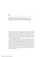
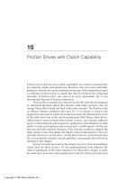
Figure 1. Mixer Block Diagram
MIXERS AND FREQUENCY DISCRIMINATORS
Mixers are used to convert a signal from one frequency to another. This is done by combining the original RF
signal with a local oscillator (LO) signal in a non-linear device such as a Schottky-barrier diode.
The output spectrum includes:
C The original inputs, LO and RF
C All higher order harmonics of LO and RF
C The two primary sidebands , LO ± RF (m,n = 1)
C All higher order products of mLO ± nRF (where m,n are integers)
C A DC output level
The desired output frequency, commonly called the intermediate frequency (IF), can be either the lower (LO-RF)
or upper (LO+RF) sideband. When a mixer is used as a down converter, the lower sideband is the sideband of interest.
A microwave balanced mixer makes use of the 3 dB hybrid to divide and recombine the RF and LO inputs to two
mixing diodes. The 3 dB hybrid can be either the 90E or 180E type. Each has certain advantages which will be covered
later. The critical requirement is that the LO and RF signals be distributed uniformly (balanced) to each mixer diode.
Figure 1 is a typical balanced mixer block diagram. The mixer diodes are reversed relative to each other; the
desired frequency (IF) components of each diode are then in-phase while the DC outputs are positive and negative
respectively.
The two diode outputs are summed in a tee where the DC terms cancel and only the desired IF component exists
at the IF port.
Power
Divider
Phase
Discriminator
Differential
Amplifiers
Signal "A" at
Frequency "f "
Delay Line
of time T
6-8.2
Figure 2. Frequency Discriminator
Other types of mixers exist, including the double-balanced mixer, and the Ortho-Quad® (quadrature fed dual)
mixer. The relative advantages and disadvantages of each of the four types are summarized in Table 1.
Table 1. Mixer Comparison
Mixer Type VSWR Conversion LO/RF Harmonic Dynamic IF
1
Loss Isolation Suppression Range Bandwidth
2 3 4
90E Hybrid good lowest poor poor-fair high wide
180E Hybrid poor low good good high wide
Double- poor low Very good - very good high extremely
Balanced excellent wide
Ortho Quad good low very good fair high wide
NOTES:
(1) Poor = 2.5:1 typical ; Good = 1.3:1 typical
(2) Conversion loss: lowest: 5-7 dB typical; Low 7-9 dB typical
(3) Poor: 10 dB typical ; Good: 20 dB typical ; Very Good: 25-30 dB typical ; Excellent: 35-40 dB typical
(4) Poor: partial rejection of LO/RF even harmonics
Fair: slightly better
Good: can reject all LO even harmonics
Very Good: can reject all LO and RF even harmonics
Used in various circuits, mixers can act as modulators, phase detectors, and frequency discriminators.
The phase discriminators can serve as a signal processing network for systems designed to monitor bearing,
polarization, and frequency of AM or FM radiated signals.
A frequency discriminator uses a phase
discriminator and adds a power divider and
delay line at the RF input as shown in Figure 2.
The unknown RF signal "A" is divided between
a reference and delay path. The differential
delay (T) creates a phase difference (2) between
the two signals which is a linear function of
frequency (f) and is given by 2 = 2BfT.
When the two output signals are fed to
the horizontal and vertical input of an
oscilloscope, the resultant display angle will be
a direct function of frequency.