Tài liệu Induction Machines pptx
Bạn đang xem bản rút gọn của tài liệu. Xem và tải ngay bản đầy đủ của tài liệu tại đây (179.75 KB, 26 trang )
ENGNG2024 Electrical Engineering
E Levi, 2002
1
INDUCTION MACHINES
1. PRELIMINARY CONSIDERATIONS
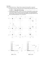
Consider an electric machine with six windings. Stator and rotor are of cylindrical
cross-section and three windings are situated on stator while the remaining three windings are
on the rotor, as shown in Fig. 1. Both stator and rotor windings are displaced in space for 120
degrees electrical. In this electromechanical converter a continual electromechanical energy
conversion may take place provided that, if angular frequency of stator currents is
ω
s
and
angular frequency of rotor currents is
ω
r
, rotor speed is
rs
ωωω
−= . Note that, according to
the condition of average torque existence, this is the only possible correlation between stator
and rotor frequency and frequency of rotation, when both stator and rotor carry AC currents.
Then the developed torque becomes time independent and equal to the average torque value.
This type of the electromechanical energy converter is called asynchronous machine (or
induction machine; the origin of this name will become clearer later), because the rotor rotates
with speed
ω
, while the stator revolving field rotates with synchronous speed
ω
s
. Rotor
currents form a revolving field as well, which rotates with angular velocity
ω
r
with respect to
rotor, while with respect to stator its angular velocity is
sr
ωωω
=+ , i.e. synchronous speed.
Note that creation of the rotating field in stator is enabled by displacing in space the three
windings of the stator by 120 degrees and by feeding these three windings with a system of
three phase currents with mutual phase displacement of 120 degrees.
Rotor
b -c Stator
Air-gap
-a a
c -b Rotor
winding
Fig.1 – Cross-section of a three-phase induction machine.
Before proceeding further into discussion of operating principles and analytical theory
of induction machines, let us here briefly review the main constructional features of induction
machines. Stator of induction machines, together with its three-phase winding, completely
corresponds to the stator of synchronous machines. This means that the stator core is
assembled of laminated iron sheets. An appropriate number of iron sheets are put together,
thus forming stator core of the necessary length. Laminated iron sheets are insulated in order
to reduce eddy-current losses in the iron core. Such a design of iron core is always utilised for
those parts of electric machine where flux density and magnetic flux is time varying. The sheets
are mutually isolated in order to prevent formation of a circuit for eddy-current flow from
sheet to sheet. The iron core material is silicon alloyed. Addition of silicon reduces hysteresis
ENGNG2024 Electrical Engineering
E Levi, 2002
2
losses in the iron core. Simultaneously, electric resistivity of the material is increased, thus
giving rise to a substantial decrease in eddy-current losses as well. Windings of induction
machine are placed into slots, which may be of open shape, or semi-closed. Semi-closed slots
are usually selected for power ratings up to 200 kW; above 200 kW slots are open.
Rotor core in induction machines is of laminated structure as well, because in rotor
windings flows AC current, giving rise to time-varying flux density in the rotor (in synchronous
machines rotor frequency is zero and rotor can be manufactured using a solid piece of
ferromagnetic material). Rotor winding is placed into rotor slots in one of the two different
ways. Subdivision of induction machines into two categories is normally done in conjunction
with the way in which the rotor winding is formed. Rotor winding may be wound three-phase
winding and such a machine is called wound-rotor induction machine or slip ring induction
machine. The latter name stems from the fact that three terminals of the rotor phases are in
wound-rotor machine brought out of the machine and connected to three slip rings (one for
each phase), while the remaining three ends of the phase windings are connected into star
neutral point and they remain inside the machine. Wound-rotor induction machine is illustrated
in Fig. 2. The purpose of slip rings is beyond the scope of interest here. Slip rings are
mechanically fixed to rotor and they rotate together with rotor. Three carbon brushes are
mounted on the stator (one for each phase) and brushes slip along the rings as they rotate, thus
establishing an electric contact between the stationary world and the rotating rotor. An electric
approach to rotor winding (which rotates together with rotor) is enabled in this way. In other
words, electric energy can be either brought or taken away from rotor winding during machine
operation through this assembly, which consists of rotating slip rings and fixed brushes.
Brushes are connected with leads to rotor winding terminals in the terminal box of the
machine. Slip rings can be short-circuited and then rotor winding becomes a three-phase short-
circuited winding. When the slip rings are short-circuited, brushes are raised and detached from
slip rings. This is the normal operating state of a slip-ring induction machine.
The second type of induction machines are so-called squirrel-cage induction machines.
Rotor winding is in this case cast into slots and it is formed of solid aluminium or copper bars.
The both ends of bars are electrically connected through end-rings. The winding manufactured
in this way resembles a squirrel cage and this explains the origin of the name. The winding is
shown in Fig. 3. Note that rotor winding is in this case always short-circuited and there is no
possibility of electrical approach to the winding. In other words, electric energy cannot be
either brought or taken away from the rotor winding. A winding formed in this way is
essentially an n-phase winding, where the number of phases n equals number of bars. However,
such an n-phase winding can be always substituted with an equivalent three-phase winding for
all analytical considerations.
As already stated at the beginning of this section, there are rotor currents in the rotor
winding whose frequency is
ω
r
. We have just seen that in a squirrel-cage induction machine
there is no electrical access to the rotor winding. Similarly, the normal operating regime of a
slip-ring induction machine is with rotor winding short-circuited; thus no electrical access is
possible to the rotor winding and the question which arises is how do we get currents in rotor
windings when we cannot approach the winding and connect an appropriate electric source.
2. OPERATING PRINCIPLES OF INDUCTION MACHINES
Consider an induction machine with a three phase winding on the stator and an
equivalent three phase short-circuited winding on the rotor. Let the stator winding be
connected to the utility supply which provides three phase balanced system of AC voltages.
These voltages will cause appropriate three phase currents to flow through stator the winding.
ENGNG2024 Electrical Engineering
E Levi, 2002
3
The currents will give rise to formation of Tesla’s revolving field in the air gap of the machine.
Given the supply frequency of stator voltages and currents f
s
in [Hz], the revolving field will
rotate in space (in the cross section of the machine) at the angular frequency of
ss
f
πω
2= .As
both stator and rotor are initially stationary, the revolving field cuts conductors of both stator
and rotor windings, causing induced electromotive forces in the windings to occur.
slip ring
b
rush
winding
terminal
A
B
C
Three-phase
winding
Slip rings
Brushes
Terminals
Shaft
Fig. 2 – Schematic representation of the rotor of a slip ring induction machine and the
physical appearance.
In stator phase a winding a counter electromotive force is induced and it balances the applied
voltage, the difference in their rms value being caused by voltage drop on the winding
resistance and leakage reactance and being equal to a couple of percents of the applied voltage
rms value. An electromotive force is induced in the rotor winding as well and its direction is
shown in Fig. 4. As the rotor winding is short-circuited, the induced electromotive force will
causeacurrentintherotorconductorsI
r
, whose real component has the same direction as
induced emf. As the conductor, which carries current I
r
, is in the magnetic field, a magnetic
force F will be created. This force will cause rotor to start rotating in the direction of stator
ENGNG2024 Electrical Engineering
E Levi, 2002
4
revolving field rotation. The same happens in all the rotor conductors and sum of all individual
multiples of rotor radius and force gives overall electromagnetic torque in the machine.
Summarising, when stator winding of a three-phase induction machine is connected to the
mains, electromagnetic induction causes currents in rotor windings and a torque is created
which pulls rotor into rotation in the direction of rotation of the stator revolving field. This
implies that transfer of electric energy from stator to rotor is realised exclusively by
electromagnetic induction; therefore asynchronous machines are called induction machines.
Rotor winding
bars
End ring
Fig. 3 – Squirrel-cage winding of a squirrel cage induction machine.
.
ω
s
Rotating field
force
force
N
S
Fig. 4 – Creation of an electromagnetic torque in an induction machine.
Rotor can never reach synchronous speed of rotation. Rotation of rotor at synchronous
speed implies that rotor rotates synchronously with revolving field. In that case there is no
relative motion between stator revolving field and rotor and no electromotive force can be
induced in the rotor windings. Consequently, no current can flow in the rotor winding if the
ENGNG2024 Electrical Engineering
E Levi, 2002
5
speed is synchronous and no electromagnetic force can be generated. Therefore at synchronous
speed the developed torque in an induction machine equals zero. As certain amount of torque
is always necessary in a machine that operates as a motor in order to cover mechanical losses,
induction motor has to operate with certain amount of developed torque even when it is not
loaded at the shaft. Thus the rotor in motoring regime can never attain synchronous speed, i.e.
it can never catch with the revolving field. When the motor is unloaded, it runs under no-load
conditions and the amount of torque that is needed is determined with mechanical losses
(windage losses and friction losses in bearings). The torque that describes mechanical losses is
small, thus indicating that the induction motor will have the highest possible speed when it runs
unloaded; this is so-called no-load speed and it is only slightly smaller from synchronous speed.
Let us summarise the above given explanations: connection of three-phase stator
winding of an induction machine at standstill to a voltage source causes current flow in stator
windings; these currents give rise to production of revolving field; revolving filed cuts
conductors of both stator and rotor windings; emf is induced in stator and it provides voltage
balance to supply voltage; emf is induced in rotor as well and it causes current flow through
short-circuited rotor winding; an electromagnetic force is created which acts on every rotor
conductor, leading to the creation of the electromagnetic torque which pulls rotor into
rotation; the direction of rotation is the same as the direction of rotation of stator revolving
field; when a steady-state is established, rotor rotates with angular velocity equal to
rs
ωωω
−= ; rotor currents create another revolving field whose absolute speed equals
synchronous speed. Therefore, the torque is consequence of mutual interaction between stator
and rotor revolving fields. At synchronous speed rotor currents become zero and
electromagnetic torque disappears.
Windings are by the virtue of their construction of resistive-inductive nature. Reactive
power has to be provided for magnetisation of iron cores and air gap between stator and rotor.
The question is how this reactive power is provided in induction machines. The machine does
not contain any capacitances that could produce reactive energy. The only electrical
connection with outside world is the connection of the stator winding to the supply, as the
rotor winding is short-circuited. This means that there is no source of reactive power available
inside an induction machine. Therefore induction machine has always to absorb reactive energy
from the supply. Under all the possible operating conditions induction machine will act as a
reactive energy consumer. As there is no rotor winding connected to another electric source,
as is the case in synchronous machines, there is no way of exciting the induction machine in a
manner similar to synchronous machines. This is one of the main reasons why induction
machine is mainly utilised in motoring regime, while synchronous machine is used for
generation purposes. When an induction machine is applied as a generator, reactive power has
to be either taken from the power system or to be provided by a static VAr compensator (e.g.,
capacitor bank).
As already emphasised, during motoring induction machine has to rotate slower than
the revolving field, even under no-load conditions. The angular velocity of the rotor is given
with
rs
ωωω
−= . Revolving fields of stator and rotor rotate with angular velocity
ω
s
.The
difference between rotor speed and synchronous speed is characterised with the so-called slip.
The slip is expressed either as a percentage value of the synchronous speed or as a per unit
non-dimensional quantity. It is usually calculated out of the speeds given in [rpm] in the
following way:
[%]100or[p.u]
s
s
s
s
n
nn
s
n
nn
s
−
=
−
= (1)
where:
ENGNG2024 Electrical Engineering
E Levi, 2002
6
n
s
- synchronous mechanical speed, which is a function of the number of magnetic pole
pairs P and which is correlated with synchronous electrical speed 60f
s
as
P
f
n
s
s
60
=
(2)
For 50 Hz supply synchronous speeds are
P1234
n
s
[rpm] 3000 1500 1000 750
n - asynchronous mechanical speed of rotation of induction machine shaft.
Note that definition of the slip and the values are the same regardless of whether speeds in
[rpm] or angular speeds in [rad/s] are used.
Slip during normal operation of induction machines is in the range 10% to 2% for
induction machines with power ratings in the range 1 kW 100 kW. The value of the slip that
corresponds to the rated operating conditions, when speed is n
n
, will be denoted as s
n
.Indexn
will in general always define the rated (nominal) operating condition of the machine.
Let us now investigate correlation between stator and rotor frequencies with respect to
newly introduced notion of slip. From slip definition of (1) it follows that
()()
rs
ss
ss
ss
s
Psnnn
nnsn
ωωω
ωωω
π
+=
+=
+=
−=
timesameat theSince
1260bydivided
(3)
it follows that the rotor frequency is determined with
srsr
sffs ==
ωω
(4)
Example 1:
A 4-pole, 3-phase induction machine is fed from 50 Hz supply and operates in steady
state with slip equal to 0.03. Determine the rotor speed and frequency of rotor
currents.
Solution:
[Hz]5.15003.0
[rpm]14551500)03.01(1
[rpm]15002/5060
60
===
=−==
===
xsff
x-s)n(n
x
P
f
n
sr
s
s
s
Example 2:
A 60 Hz induction motor has one pole pair and runs at 3150 rpm. Calculate the
synchronous speed and slip in per unit and in percents.
Solution:
Note the this is an American machine, since the frequency is 60 Hz. Hence
%5.2100]p.u.[[%]
025.03600/)31503600(/)(]p.u.[
[rpm]36001/6060
60
==
=−=−=
===
xss
nnns
x
P
f
n
ss
s
s
ENGNG2024 Electrical Engineering
E Levi, 2002
7
According to (4), frequency of the current in rotor is slip times frequency of stator
currents. For 50 Hz stator frequency and operating slips of 10% to 2% in an induction machine
rotor frequency is only 5….1 Hz. Consequently, as the losses in the iron core are proportional
to frequency and frequency squared, it follows that rotor iron losses are going to be negligibly
small and that the major part of the iron loss will take place in stator. The total iron loss in an
induction machine is for this reason always assumed to take place in stator only.
According to the slip definition, equation (1), slip is a variable determined with the
speed of rotation. This implies that frequency of rotor currents is, according to (4), a variable
as well, proportional to the slip. Characteristic slip values in motoring operation are:
n = 0 rotor at standstill s = 1
0<n<n
0
rotor rotates, machine is loaded 1 > s > s
0
n=n
0
<n
s
no-load, machine is unloaded s = s
0
n=n
n
<n
0
rotor rotates, rated load s = s
n
Normal operating range of induction machines in steady-states is in the speed range between
rated speed and no-load speed, the actual operating speed being dependent on the load torque
that the motor is driving.
Suppose now that a source of mechanical energy is connected to the induction machine
shaft and that the mechanical power provided by mechanical source is exactly equal to the
power which describes mechanical losses (i.e. mechanical source provides torque to overcome
mechanical loss torque). Then the speed of rotation will become equal to synchronous, as the
mechanical loss torque is equated by torque of the prime mover. Simultaneously the induction
machine torque will become equal to zero. Therefore at synchronous speed
00 ===
es
Tsnn
Suppose now that the power provided by the prime mover increases. The induction machine
then enters generating regime. Note that only real power will be generated, while the reactive
power is still absorbed. For generation
00 <<>
es
Tsnn
This means that in generation speed is above synchronous speed, slip is negative and the
machine’s electromagnetic torque is negative as well. In contrast to this, in motoring slip and
torque are positive since the reason for rotation is the machine’s electromagnetic torque. A
representation of induction machine operating modes is given in Fig. 5.
Motoring Generating
10-0.5s
0n
s
1.5n
s
n
Fig. 5 – Schematic representation of induction machine operating modes, in terms of slip and
speed of rotation.
Given the slip s in a steady state, speed can be determined from equation (1) as
ENGNG2024 Electrical Engineering
E Levi, 2002
8
[]
()
[]
()
[rpm]100/%1
[rpm]p.u.1
s
s
nsn
nsn
−=
−=
(5)
Taking into account that during motoring slip is within the range from 1 to 0, it is obvious that
frequency of rotor currents varies as a function of slip in the range between stator frequency
and zero. At standstill rotor frequency equals stator frequency, while at synchronous speed
rotor frequency becomes equal to zero. Therefore it follows that frequency of rotor currents
and voltages is determined with slip.
3. ANALYTICAL THEORY OF INDUCTION MACHINE OPERATION
It can be shown that a balanced three-phase induction machine fed from symmetrical
sinusoidal three-phase supply can be treated in terms of per-phase equivalent circuit in steady
state. However, such a derivation is pretty involved and time consuming. As only steady states
under symmetrical supply conditions are of interest here, complex representatives of AC
sinusoidal quantities may be used (phasors). Furthermore, for the purpose of steady-state
analysis of a balanced induction machine fed from symmetrical source, the whole analysis can
be performed by utilising per phase representation with complex phasors. Such an approach is
utilised in what follows.
Let stator winding be connected to mains, which provide symmetrical three-phase
voltages and let rotor be at standstill, so that rotor speed is zero. Frequency of stator voltages
and currents is f
s
. An electromotive force will be induced in rotor winding that will cause
current to circulate around the rotor winding. As the rotor is at standstill, slip equals one and
the frequency in rotor winding equals stator frequency. When the rotor is at standstill,
difference between the speed of the rotating field and the rotor speed is of maximum value and
equals synchronous speed. This speed difference determines the induced emf, since the emf is
directly proportional to the speed at which the conductors are cut by the field (i.e. to the
difference between the synchronous speed and the rotor speed). Once when rotor rotates at
certain speed, the speed at which conductors are cut by the rotating field will be determined
with
ssr
sf
πωωω
2=−= and will be smaller than at standstill.
When the rotor is at standstill let the induced electromotive force in one rotor phase E
is identified with index rl. Its existence will cause current flow and rotor currents produce
corresponding revolving field and flux. One part of the flux dissipates around the rotor winding
(leakage flux), while major part links with stator windings contributing to the mutual flux.
Current flow through rotor winding, caused by induced emf, is opposed by the resistance of
the rotor winding and leakage reactance (which describes leakage flux). The value of the rotor
leakage reactance is again frequency dependent. At standstill rotor frequency, rotor leakage
reactance and modulus of rotor current are
22
22
rlr
rl
rl
rsrrrl
ssr
XR
E
I
LfLfX
fsff
+
=
==
==
γγγ
ππ
(6)
Suppose now that the rotor starts rotating, so that slip becomes smaller than 1 since
speed is greater than one. According to the fundamental expression for induced electromotive
force due to the relative movement of a conductor with respect to flux density, induced emf is
proportional to the relative speed of conductor with respect to flux density. As the rotor
rotates with certain speed, while revolving fields rotate with synchronous speed, relative speed
ENGNG2024 Electrical Engineering
E Levi, 2002
9
of the revolving field with respect to the rotor conductors is equal to the rotor angular
frequency. This means that induced electromotive force at slip s is proportional to frequency of
rotor currents. Consequently, at any other speed different from zero,
()
2
2
22222
1
1
rr
rl
r
rlr
rl
rr
r
r
rlr
rlr
rlr
XsR
E
I
XsR
sE
XR
E
I
sXX
sEE
ssEE
γ
γγ
γγ
+
=
+
=
+
=
=
==
≠=
(7)
The expression for modulus of the rotor current in (7) enables the following phasor equation
(phasors are identified with a bar over the symbol) to be written:
r
rl
r
r
rl
rlr
rl
r
r
r
IjXI
s
R
E
EsIjsXIRE
γ
γ
+=−
−=+=−
(8)
Equation (8) enables construction of the rotor per-phase equivalent circuit, shown in Fig. 6.
Let us consider now voltage balance for one stator phase winding. Stator phase
winding is characterised with resistance and stator leakage reactance. Note that for stator
rotating field always cuts the conductors at the same, synchronous speed. Hence the frequency
of the stator is constant (50 Hz) and the induced emf is proportional to this fixed frequency
regardless of the speed of rotation of the rotor. The induced emf exists in each stator phase and
it holds balance to the applied stator voltage. Following the same approach as for the rotor
phase, one can immediately write the phasor voltage equation for one stator phase as:
ss
s
s
s
EIjXIRV ++=
γ
(9)
Corresponding equivalent circuit for one stator phase is shown in Fig. 7.
jX
γ
rl
I
r
E
rl
R
r
/s
Fig. 6 - Rotor per-phase equivalent circuit
R
s
jX
γ
s
I
s
VE
s
Fig. 7 – Stator per-phase equivalent circuit.
By combining Figures 6 and 7, resulting complete equivalent circuit can be constructed.
It is shown in Fig. 8 and is described with the following two voltage phasor equations:
ss
s
s
s
EIjXIRV ++=
γ
(10)
ENGNG2024 Electrical Engineering
E Levi, 2002
10
r
rl
r
r
rl
IjXI
s
R
E
γ
+=− (11)
R
s
jX
γ
s
I
s
VE
s
jX
γ
rl
I
r
E
rl
R
r
/s
Fig. 8 – Induction machine per-phase equivalent circuit.
Two circuits shown in Fig. 8 apply to two different voltage levels, since the induced
emf in stator is in general different from the induced emf in rotor. It is therefore not possible to
directly connect them. In order to be able to put the two circuits together, it is necessary to
apply transformer theory, which means that rotor voltage needs to be referred to stator voltage
level (as the secondary is referred to primary using the transformation ratio in transformers).
Correlation between the stator and rotor induced emf is established at standstill through the
transformation ratio
m. Transformation ratio is defined as
rls
rl
EEEEm
s
// == (12)
and in an induction machine it is dependent on design features. Rotor voltage equation (11) is
multiplied next with the transformation ratio
r
rl
r
r
rl
r
rl
r
r
rl
IjmXI
s
mR
Em
IjXI
s
R
E
γ
γ
+=−
•+=− m/
(13)
and new fictitious rotor variables, referred to stator, are then introduced respecting the
condition that power in terms of original variables and in terms of new (primed) variables has
to be the same:
mII
IEIE
EmE
rr
rrrr
rlrl
=
=
=
'
''
'
(14)
Rotor current and induced emf in (13) are replaced next with the new rotor current and new
induced emf
'''
2
2
r
rl
r
r
rl
IXjmI
s
Rm
E
γ
+=− (15)
Finally, new rotor parameters (primed symbols) are introduced and the equation is brought into
final form of
rlrlrr
r
rl
r
r
rl
XmXRmR
IjXI
s
R
E
γγ
γ
22
''
'''
'
'
==
+=−
(16)
ENGNG2024 Electrical Engineering
E Levi, 2002
11
The left-hand side of (16) is now, by definition in (12), equal to the stator induced emf. It is
therefore possible to connect the two circuits into a single circuit, shown in Fig. 9, which is
described with the following two voltage equations:
()
'''
r
rlr
s
ss
s
s
s
IjXsRE
EIjXIRV
γ
γ
+=−
++=
(17)
R
s
jX
γ
s
jX
γ
rl
’
I
s
I
r
’
VE
s
= E
rl
’R
r
’/s
Fig. 9 – Connection of the stator and rotor per-phase equivalent circuit into a single electric
circuit after referring rotor to stator.
Note that the phasors are identified in all the equations with a bar over the symbol, while in
Figs. 6-9 (and subsequent figures as well) phasors are denoted with a bold symbol.
What remains to be done in Fig. 9 is to express the induced emf in terms of an
appropriate impedance. This can be done in the same manner as in transformer theory, by
utilising the notions of the magnetising current and magnetising reactance. Phasor sum of the
stator and referred rotor current is defined as the magnetising current, and induced emf is
expressed as a voltage across the magnetising reactance caused by the flow of the magnetising
current:
'
rsm
m
m
s
III
IjXE
+=
=
(18)
The final equivalent circuit, which suffices for most of the calculations, results in this way. It is
illustrated in Fig. 10.
R
s
jX
γ
s
jX
γ
rl
’
I
s
I
r
’
V
jX
m
R
r
’/s
I
m
Fig. 10 – Per-phase equivalent circuit of an induction machine, with rotor winding referred to
stator.
In all the considerations so far iron loss was neglected. As already noted, it occurs
predominantly in stator and its existence can be accounted for by adding so-called equivalent
iron loss resistance into the circuit, in parallel to the magnetising reactance. If iron loss needs
to be taken into consideration, then the equivalent circuit of Fig. 10 becomes as in Fig. 11.
ENGNG2024 Electrical Engineering
E Levi, 2002
12
R
s
jX
γ
s
jX
γ
rl
’
I
s
I
r
’
VI
Fe
jX
m
R
r
’/s
R
m
I
m
Fig. 11 – Equivalent per-phase circuit of an induction machine with included iron loss
representation.
Note that the addition of the equivalent iron loss resistance in Fig. 11 changes the node current
balance equation. From Fig. 11
'
rsmFe
IIII +=+
(19)
Note as well that the fact that rotor parameters in the circuit of Fig. 11 are referred to stator is
irrelevant, since in a cage induction machine it is anyway not possible to determine actual rotor
parameter values. Since tests used to calculate parameters are performed by feeding the
machine from stator and by doing measurements at the stator side, parameter values obtained
by means of experiments (described in the next section) are anyway rotor parameters referred
to stator (i.e. as seen from the stator side).
Example 3:
A squirrel cage three-phase induction motor has the following parameters:
R0.39 R XX0.35 X=16
sr
'
sr
'
m
====ΩΩ ΩΩ014.
γγ
The motor is four-pole, three-phase, with star connected stator winding, rated
frequency is 60 Hz and rated voltage is 220 V. Rated speed is 1746 rpm. Mechanical
and iron loss may be neglected.
Calculate slip, power factor, stator current and input power of the motor when it
operates under rated conditions.
Solution:
Note that since the rated speed is 1746 rpm and the motor is four-pole, the operating frequency must
be 60 Hz, since rated slip has to be positive and of the order of a couple of percents.
03.01800/)17461800(/)(
[rpm]1746
[rpm]18002/6060/60
=−=−=
=
===
snsn
n
ss
nnns
n
xPfn
The motor is star connected. Hence the phase voltage is 220/√3=127V.
In order to find the stator current, it is necessary to solve the equivalent circuit of Fig. 10, in which the
magnetising reactance is included. From the circuit of Fig. 10 one has:
Ω+=+++=
+
++=
Ω=
Ω+=+=
)87.1525.4()52.1135.4()35.039.0(
16
)35.067.4(''
jjj
ZZ
ZZ
jXRZ
jZ
jjXsRZ
rm
rm
ss
in
m
rlnr
r
γ
γ
The modulus and the phase of the input impedance are
48.22)897.4/525.4(cos}/]{Re[cos
897.487.1525.4
11
22
===
Ω=+=
−−
in
in
n
in
ZZ
Z
φ
ENGNG2024 Electrical Engineering
E Levi, 2002
13
Stator rated current and power factor are therefore
924.0cos
A269.4/127/
)(
=
===
n
inphnsn
ZVI
φ
The input power is
W91310924261273cos3
)(
=== xxxIVP
nsnphnin
φ
Example 4:
A squirrel cage three-phase induction motor has the following parameters:
0.35XX14.0R0.39R
'
rs
'
rs
Ω==Ω=Ω=
γγ
The motor is four-pole, three-phase, with star connected stator winding, rated
frequency is 60 Hz and rated voltage is 220 V. Rated speed is 1746 rpm. Mechanical
and iron loss may be neglected. Magnetising reactance may be regarded as of infinite
value.
Calculate slip, power factor, stator current and input power of the motor when it
operates under rated conditions.
Solution:
Note that all the data in this example are the same as in the previous one. The only difference is that
the magnetising reactance is now omitted from the equivalent circuit. Such an approximation enables
much simpler calculations. However, it is unrealistic for normal operating slip values, since it yields
an unrealistically high value of the power factor. Rated slip value is calculated as in the previous
example,
03.01800/)17461800(/)(
[rpm]1746
[rpm]18002/6060/60
=−=−=
=
===
snsn
n
ss
nnns
n
xPfn
and the rated phase voltage is again 127 V. Impedance calculation is however now much simpler,
W939899.09.241273
99.0108.5/06.5cos
A9.24108.5/127
108.57.006.5
)7.006.5()35.067.4()35.039.0(
)35.067.4(''
22
==
==
==
Ω=+=
Ω+=+++=++=
Ω+=+=
xxxP
I
Z
jjjZjXRZ
jjXsRZ
in
sn
in
r
ss
in
rlnr
r
φ
γ
γ
Comparing the results obtained with and without the magnetising branch, one can see that the error in
the stator rms current is rather small (26 A against 24.9). Similar conclusion applies to the real input
power (9131 W against 9398 W). However, the error in the power factor is significant (0.924 against
0.99) since when the magnetising branch is neglected reactive power taken by the machine is almost
zero (only reactive power for the leakage reactances exists now, in contrast to the real case when most
of the reactive power appears across the magnetising reactance).
4. NO-LOAD AND LOCKED-ROTOR REGIMES OF AN INDUCTION MACHINE
No-load and mechanical short-circuit (locked-rotor, rotor at standstill) are two
important regimes of an induction machine which occur during normal operation and which are
performed as standard tests on induction machines as well. When performed as tests, these two
tests enable calculation of the parameters of the equivalent circuit, determination of mechanical
losses and calculation of iron core losses. Here no-load state and rotor at standstill condition
are discussed only as regimes that appear in normal operation of the motor.
ENGNG2024 Electrical Engineering
E Levi, 2002
14
Under no-load conditions the induction motor is connected during normal operation to
rated voltage supply and there is no mechanical load connected to the shaft. Therefore
000 ===
η
outL
PT (20)
and motor torque is just sufficient to overcome the mechanical losses. In this operating state
the motor draws from the mains reactive power for magnetisation of the magnetic circuit
(which is basically independent of the operating regime of the machine and can be regarded as
being the same, for the same voltage, for any load) and real power to cover its internal no-load
losses. The speed of rotation is very close to the synchronous speed, i.e. slip differs only
slightly from zero. No-load losses consist of mechanical losses, iron core losses and stator
winding copper no-load losses:
mechlossFeCusin
PPPPP
−
++==
00
(21)
Stator copper losses are determined with the no-load current that flows through stator
windings. Iron core losses exist practically only in the stator as rotor frequency is almost zero.
Iron losses, being dependent on frequency and flux density, are independent of mechanical load
and depend only on applied voltage and stator frequency. In other words, for rated voltage and
frequency, iron losses are the same for any load as under no-load conditions.
Since slip in no-load operation is practically zero, the resistance
sR
r
'intherotor
branch of the circuit in Fig. 11 tends to infinity. This means that there are hardly any rotor
currents flowing (rotor current is only of such a small value that is required to produce motor
electromagnetic torque to overcome mechanical losses). Hence the rotor circuit can be open-
circuited and the equivalent circuit for no-load operation becomes as shown in Fig. 12.
R
s
jX
γ
s
I
s0
I
r0
’=0
V
n
I
Fe
jX
m
R
r
’/s = infinity
R
m
I
m0
Fig. 12 – Equivalent circuit for no-load operation.
The equivalent circuit of Fig 12 neglects mechanical losses. Therefore, as far as the
equivalent circuit is concerned, no-load is characterised with slip equal to zero.
Power factor for no-load operation is
0
0
0
3
cos
sn
IV
P
=
φ
(22)
and its value is very small (typically 0.1 to 0.2), as the real power drawn from the supply is
small and just equal to losses which exist under no-load conditions (there is no output power
as there is no mechanical load connected to the machine). At the same time, the reactive power
drawn from the mains is basically the same as it is when machine delivers its mechanical
output (real) power equal to rated. No-load current in induction machines is in the range from
30% to 80% of the rated current. This is significantly higher than for transformers, the reason
being the existence of the air gap that requires large reactive power for magnetisation. Typical
value of mechanical losses is one third of rated iron core losses.
ENGNG2024 Electrical Engineering
E Levi, 2002
15
No-load running condition will exist whenever machine runs without load. If no-load
test is to be performed, then variable voltage supply (50 Hz) is needed, such as a variac. The
test enables exact calculation of iron core losses, mechanical losses and shunt parameters of the
equivalent circuit (magnetising reactance and equivalent iron core resistance).
Another characteristic state of an induction motor is mechanical short-circuit, which is
in no way connected to, and thus is not to be confused with, electric short-circuit. Mechanical
short-circuit simply denotes an induction machine whose stator winding is supplied with three-
phase symmetrical voltages and whose rotor does not rotate (i.e. the rotor is at standstill). This
state is met whenever an induction motor is connected to the supply from standstill and is then
called staring condition or just starting. Obviously, as the machine will start rotating when it is
being fed (provided that rotor is not prevented from rotating), this state will last for a very
short period of time in normal operation of induction machines.
As the rotor is at standstill, s =1,n = 0, and therefore
000 ≠==
eout
TP
η
(23)
Note that although there is no electromechanical conversion as the rotor is at standstill, torque
does not equal zero. When the motor starts running-up (s = 1) and the voltage equals rated
value, this being the normal starting condition for induction motors, torque has a characteristic
value which is called starting torque. The corresponding stator current is called starting current
and its typical value is five to eight times the rated motor current. The issue is elaborated in
more detail in the next section.
Mechanical short-circuit is at the same time a test which is performed on induction
machines. During the test rotor is prevented from rotating and it is forced to remain at
standstill. This test is most frequently termed as locked rotor test (it is for this reason that
index l was used to identify rotor quantities when slip equals one). It enables determination of
remaining equivalent circuit parameters (series parameters). Locked rotor test is performed
with a reduced value of stator voltage, such that it causes rated stator current to flow through
stator winding, with rotor being locked. The reason why the voltage has to be reduced is that,
when rotor is locked, slip remains equal to unity and the input impedance into the equivalent
circuit has very low value. Thus, application of the rated voltage would cause very high stator
current to flow. In some machines this value would be even ten times greater than rated
current. Consequently, the test is performed with voltage value that is just sufficient to cause
rated stator current to flow. The value of the voltage is for machines of low power rating
above one third of the rated voltage, while for machines of high power rating it is in between
one sixth and one third of the rated voltage.
During locked-rotor test the motor is supplied with voltage which is significantly lower
than the rated value. As the iron core losses are proportional to the voltage squared, this
implies that for locked-rotor test iron core losses have very small value and thus they can be
neglected. In other words, the resistance that describes iron core losses in equivalent circuit
can be omitted. Due to significantly reduced value of the voltage, reactive power absorbed by
the machine is significantly reduced as well, because the flux density that has to be established
in the core is very low. Therefore magnetising reactance can be omitted for locked-rotor test.
The equivalent circuit of Fig. 11 reduces therefore for locked-rotor condition to the equivalent
circuit given in Fig. 13. Stator voltage and current, and input real power are measured during
the test.
The same equivalent circuit of Fig. 13 can be used in discussion of starting of the motor
with rated voltage. In that case voltage equals rated and stator current becomes starting
current. This is actually the case illustrated in Fig. 13. The reason why the same assumptions as
for the locked rotor test with reduced voltage remain valid is the following. When slip equals
one, impedance of the rotor part of the circuit is very small (the smallest possible). This small
ENGNG2024 Electrical Engineering
E Levi, 2002
16
impedance is paralleled with the magnetising branch impedance, which is large. The resulting
impedance is therefore very close in value to the small impedance. This means that the
magnetising branch can be neglected without much impact on the accuracy of the calculations.
R
s
jX
γ
s
jX
γ
rl
’
I
st
I
rst
’=-I
st
V
n
R
r
’
Fig. 13 – Induction motor per-phase equivalent circuit for locked rotor test and for
investigation of the starting. The circuit is shown assuming starting, so that the stator voltage
is rated and stator current equals starting current.
Power factor for the standstill condition is typically in the range between 0.4 and 0.6.
Mechanical losses are equal to zero and iron losses can be neglected. Hence, in the locked
rotor test, measured stator current and measured input power with known applied voltage
enable calculation of the parameters of the circuit shown in Fig. 13 (except for stator
resistance, that is measured beforehand using an ohm-metre).
Let us note once more that an induction motor, when connected to the supply, will
start running-up from mechanical short-circuit state. This state will last shortly, because the
speed will start increasing very soon after the motor is switched on. During that short time
interval a stator current flows which is significantly greater than the rated current.
Example 5:
A three-phase squirrel-cage induction motor with star-connected stator winding, 380
V, 50 Hz, has the stator resistance of 0.26 Ω per phase. Under no-load conditions the
machine consumes 400 W and the no-load current equals 3 A.
Determine from no-load test data the following: no-load power factor, iron loss and
mechanical loss if iron loss is 1.5 times the mechanical loss, and parameters of the
magnetising branch.
Solution:
Under no-load condition slip is approximately zero, so that the equivalent circuit of Fig. 12 applies.
From the given measurements:
W7
W8.235
W2.157
getsone5.1since
W400326.03
2.0
33803
400
3
cos
0
2
00
0
0
0
=
=
=
=
=++=++=
===
−
−
−−
Cus
Fe
mechloss
mechlossFe
mechlossFemechlossFeCus
sn
P
P
P
PP
PPxxPPPP
xxIV
P
φ
In order to find the parameters of the magnetising branch (equivalent iron loss resistance and
magnetising reactance), one neglects the voltage drop on the stator impedance, as well as the stator
leakage reactance. Then
E
s0
=V
n(ph)
=220V
and
ENGNG2024 Electrical Engineering
E Levi, 2002
17
Ω=
==
=
==
Ω===
==
75
VAr1933sin3
/3/33
8.6158.235/2203/3/33
00
2
0
2
0
2
22
0
2
0
2
m
snm
msmmsmmm
FesFeFesFeFeFe
X
IVQ
QEXXEIXQ
xPERREIRP
φ
Example 6:
A locked rotor test was performed on 3-phase, star-connected, 50 Hz, four-pole
induction machine. The input power was 20 kW, with voltage of 220 V (line-to-line)
and with current of 90 A. Calculate the motor parameters if stator resistance is 0.3 Ω.
Solution:
Since the test under consideration is the locked rotor test, the circuit of Fig. 13 applies. All of the input
power is lost in the two resistances of this circuit. Hence
()
()
Ω===
Ω=−=+−=+
Ω===
Ω=
+=+==
575.02/15.1'
15.182.041.1''
41.1)903/(220/
52.0'
90)'3.0(3'3kW20
22
2
2
22
rls
rsinrls
sphin
r
rsrsin
XX
RRZXX
xIVZ
R
RIRRP
γγ
γγ
Note that it is not possible to separate total leakage reactance into stator and rotor part in an exact
manner. For vast majority of induction machines it can be assumed however that stator and rotor
leakage reactance are mutually equal.
Example 7:
A squirrel cage three-phase induction motor has the following parameters:
R0.5 R XX0.4
sr
'
sr
'
== ==ΩΩ Ω025.
γγ
The motor is four-pole, three-phase, with star connected stator winding, rated
frequency is 50 Hz and rated voltage is 415 V. Calculate starting current of the motor.
Solution:
Once more the circuit of Fig. 13 applies for the calculation of the starting current. From this circuit
()
()
A6.288
8.075.0
240
''
2222
)()(
=
+
=
+++
==
rlsrs
phn
in
phn
st
XXRR
V
Z
V
I
γγ
5. TORQUE CHARACTERISTIC OF AN INDUCTION MACHINE
As a starting point in derivation of induction machine torque characteristic it is
convenient to utilise per-phase equivalent circuit, which is for convenience redrawn in Fig. 14,
for an arbitrary speed, i.e. slip s. In this equivalent circuit there exists a fictitious resistor in the
rotor circuit,
sR
r
' , which essentially represents two resistances. The first one is the physical
rotor winding resistance (referred to stator), while the second one is a fictitious resistor on
which power conversion takes place in the equivalent circuit:
()
ssRRsR
rrr
−+= 1''' (24)
It is therefore possible to re-draw the equivalent circuit in the form shown in Fig. 15. Here
rotor winding losses occur as power dissipated on the resistor '
r
R , while power that is
ENGNG2024 Electrical Engineering
E Levi, 2002
18
converted from electrical to mechanical (or vice versa in generation) appears as power
dissipated on the fictitious resistor
()
ssR
r
−1'.
R
s
jX
γ
s
jX
γ
rl
’
I
s
I
r
’
VI
Fe
jX
m
R
r
’/s
R
m
I
m
Fig. 14 – Equivalent per-phase circuit of an induction machine with included iron loss
representation.
R
s
jX
γ
s
jX
γ
rl
’R
r
’
I
s
I
r
’
VI
Fe
jX
m
(1-s)R
r
’/s
R
m
I
m
Fig. 15 – An alternative form of the equivalent circuit.
Input real power absorbed from the electric source and the stator winding and stator
iron losses are from Fig. 15
2
2
3
3
cos3
FeFeFe
ssCus
sin
IRP
IRP
VIP
=
=
=
φ
(25)
Stator voltage is assumed to be rated at all speeds and index n is therefore omitted. If the
stator power loss is subtracted from total input real power, the power that is being transferred
from stator to rotor is obtained. This power will be called transferred power and it will be
identified with an index sr meaning stator to rotor. It describes power that is transferred by
electromagnetic induction from stator to rotor. This power will further be partially lost on the
resistor '
r
R (rotor copper loss), while the major part will be converted into mechanical power.
The converted power appears across the resistor
()
ssR
r
−1' . Finally, converted power
includes the mechanical loss, so that the output power is slightly smaller. Hence
mechlosscout
Cursrc
FeCusinsr
PPP
PPP
PPPP
−
−=
−=
−−=
(26)
An illustration of the power flow in an induction machine is given in Fig. 16. Note that as this
is a per-phase equivalent circuit, only one third of a respective power appears in the per-phase
circuit. It should be noted once more that equivalent circuit does not account for mechanical
losses. Therefore the power developed at fictitious resistor is the total mechanical power, i.e.
ENGNG2024 Electrical Engineering
E Levi, 2002
19
the converted power which is the sum of mechanical losses and useful power delivered to the
load. Efficiency of the induction motor is of course given with the ratio of the output to input
power. Torque of the machine, which is called electromagnetic torque, can be obtained if the
converted power is divided by angular speed of the rotor and the converted power is expressed
as power dissipated on the fictitious resistor in Fig. 15,
P
Cus
/3 P
Cur
/3
P
sr
/3
P
in
/3 P
c
/3
P
Fe
/3
Fig. 16 – Power flow in the per-phase equivalent circuit
2
2
'
'
3
)1(
'
1
'3
r
r
s
e
s
mce
rrc
I
s
R
T
s
PT
R
s
s
IP
ω
ωω
ω
=
−=
=
−
=
(27)
The equation (27) assumes that the machine is of two-pole structure. The actual number of
pole pairs will be accounted for later on in a simple way.
In order to arrive at the torque expression in terms of terminal conditions (i.e. supply
voltage) it is necessary to further eliminate rotor current from (27). This can be done by
considering the complete equivalent circuit of Fig. 15, which needs to be at first solved for
stator current. Rotor current can then be found using current divider rule. However, the
resulting expression is quite complicated and an approximation is therefore usually made in
derivation of the torque characteristic. It is noted that the motor torque describes real power,
while the branch with the magnetising reactance describes predominantly reactive power (iron
loss is very small). Hence it is convenient to omit the magnetising branch of the circuit and
calculate the rotor current using the approximate circuit of Fig. 17.
R
s
jX
γ
s
jX
γ
rl
’
I
s
I
r
’=-I
s
V R
r
’/s
Fig. 17 – Equivalent circuit for derivation of the torque characteristic.
If magnetising branch is neglected then
ENGNG2024 Electrical Engineering
E Levi, 2002
20
()
()
()
()
22
22
''
'
''
'
rlsrs
r
rlsrse
ers
XXsRR
V
I
XXsRRZ
ZVII
γγ
γγ
+++
=
+++=
==
(28)
Substitution of (28) into (27) enables the torque characteristic to be derived in the following
form:
()
()
()
()
22
2
22
2
''
'
2
3
''
'
3
rlsrs
r
s
e
rlsrs
r
s
e
XXsRR
V
s
R
f
T
XXsRR
V
s
R
T
γγ
γγ
π
ω
+++
=
+++
=
(29)
For a machine with P pairs of poles
()
()
22
2
''
'
2
3
2
rlsrs
r
s
e
ss
XXsRR
V
s
R
P
f
T
Pf
γγ
π
π
ω
+++
=
=
(30)
Equation (30) indicates that torque is a function of slip. Torque as function of slip is displayed
in Fig. 18, where characteristic values for motoring are indicated as well. Torque
characteristic, shown in Fig. 18, is the so-called static torque characteristic, as it gives steady-
state torque values for different slips. A characteristic that includes generation is shown in Fig.
19. According to the Fig. 18, the following characteristic torque values can be identified:
()
()
22
2
''
'
2
3
:1=torque,Starting
rlsrs
r
s
st
XXRR
R
PV
f
T
s
γγ
π
+++
=
(31)
()
()
2
2
2
2
2
'
4
3
'
'
:torque(maximum)out-pullandslipout-Pull
rlsss
s
p
rlss
r
p
XXRR
V
P
f
T
XXR
R
s
γγ
γγ
π
+++±
±=
++
±= (32)
Note that pull-out slip is found by differentiating the torque expression with respect to slip and
equating the derivative to zero. Expression for pull-out slip is further substituted into torque
expression to find the maximum torque value.
Rated torque:
()
()
22
2
''
'
2
3
rlsnrs
n
r
s
en
XXsRR
V
s
R
P
f
T
γγ
π
+++
=
(33)
Note that the pull-out maximum torque in motoring and generation has different values,
although the absolute value of the pull-out slip is the same. In general
ENGNG2024 Electrical Engineering
E Levi, 2002
21
pMpG
TT > (34)
T
e
maximum (pull-out) torque V = V
n
T
en
T
st
operating region
slip
1s
p
s
n
0s
0n
syn
speed
Fig. 18 – Torque characteristic of an induction motor in motoring.
T
e
T
p
maximum (pull-out) torque V = V
n
Motoring
T
en
T
st
operating region
-s
p
slip
1s
p
s
n
0-s
n
s
Generating
-T
en
-T
p
Fig. 19 – Torque slip characteristic for both motoring and generating.
Stable operation of an induction machine is possible only at those parts of the torque
characteristic where the derivative dT
e
/ds > 0, i.e. in the region from the pull-out torque in
motoring to the pull-out torque in generation. In the stable region of operation every change of
load torque causes corresponding change in machine torque and new steady-state is reached,
ENGNG2024 Electrical Engineering
E Levi, 2002
22
with new value of slip (speed). If the load torque exceeds pull-out torque, torque equilibrium
equation cannot be satisfied any more, because induction machine cannot develop a torque
higher than pull-out torque. Therefore induction machine is brought to a halt. Stable motoring
in the region with slip values higher than pull-out slip is not possible, because in that region
every deceleration (reduction in speed) caused by an increase in the load torque, leads to
further reduction of the motor torque; consequently further deceleration takes place and the
machine again reaches halt. Analogous considerations are valid for the generating regime.
It should be noted that when a motor is switched on to the supply from standstill it
passes through all the points at the torque characteristic, from s =1(n = 0) to the steady-state
operating point, say rated speed. In the steady-state operating point the slip is a couple of
percents. However, this is a transient during which motor only passes through unstable region
and settles down on the stable part of the characteristic, in an operating point that corresponds
to load requirements.
As already noted, shown torque slip characteristic is obtained assuming steady state
conditions at each individual slip value. However, steady-state is only possible in the stable
operating region. Actual torque dynamic behaviour is quite different during the transient and it
cannot be obtained using phasors and steady state equivalent circuit. A more sophisticated,
time-domain model is required for this purpose, which has to be solved using a computer. An
illustration of the dynamic torque behaviour during acceleration from standstill under no-load
conditions is shown in Fig. 20.
Fig. 20 – Torque behaviour during acceleration from standstill under no-load conditions.
Example 8:
If the power transferred from stator to rotor in an induction machine is 120 kW when
the machine runs at slip of 0.05, calculate the rotor copper loss and the power
converted from electrical to mechanical. For the same machine stator copper loss is 3
kW, mechanical loss is 2 kW, and iron loss is 1.7 kW. Determine the useful output
power and the motor efficiency.
Solution:
ENGNG2024 Electrical Engineering
E Levi, 2002
23
Power transferred from stator to rotor, rotor copper loss and converted power are correlated as follows:
kW114120)05.01()1(
kW612005.0
Hence
'
'3
''3
'
1
'3
2
2
2
=−=−=
===
=+=
=
−
=
src
srCur
r
rCurcsr
rrCur
rrc
PsP
xsPP
s
R
IPPP
RIP
R
s
s
IP
The input power, output power and efficiency are then
%7.89897.07.124/112
kW1122114
kW7.1247.13120
====
=−=−=
=++=++=
−
inout
mechlosscout
FeCussrin
PP
PPP
PPPP
η
Example 9:
A squirrel cage three-phase induction motor has the following parameters: stator and
rotor resistance equal to 0.05 Ω each, stator and rotor leakage reactance equal to 0.15
Ω each. Rotor parameters are referred to stator and magnetising branch of the circuit
may be neglected. The machine operates at 50 Hz, 415 V, stator winding is star
connected and the number of poles is 2.
a. Calculate the rated torque and rated power if the rated slip is 0.05 and
mechanical losses may be neglected.
b. Calculate the pull-out slip and pull-out torque in motoring.
c. calculate the starting current and starting torque. Will the motor be able to start
a load whose torque is constant and equal to the rated motor torque.
Solution:
a. Since rated slip is known, one finds the rated torque using torque equation
()
()
()
kW66.13715.314)05.01(25.461)1(
thenispowerRated
Nm25.461
)15.015.0(05.0/05.005.0
240
05.0
05.0
1
502
3
''
'
2
3
2
2
2
22
2
=−=−==
=
+++
=
+++
=
xxsTTP
T
XXsRR
V
s
R
P
f
T
snennenn
en
rlsnrs
n
r
s
en
ωω
π
π
γγ
b. Pull-out slip and pull-out torque in motoring are
()
1644.03.005.0/05.0
'
'
22
2
2
=+=
++
=
rlss
r
p
XXR
R
s
γγ
()()
()
Nm6.776
)15.015.0(1644.0/05.005.0
240
1644.0
05.0
1
502
3
''
'
2
3
2
2
2
22
2
=
+++
=
+++
=
π
π
γγ
p
rlsprs
p
r
s
p
T
XXsRR
V
s
R
P
f
T
Note that pull-out torque is found simply by substituting the pull-out slip value into the general torque
equations. There is therefore no-need to memorise the expression for pull-out torque in which the pull-
out slip is eliminated using the corresponding pull-out slip expression.
c. Starting current and starting torque are:
ENGNG2024 Electrical Engineering
E Levi, 2002
24
()
()
A759
3.01.0
240
''
2222
)()(
=
+
=
+++
==
rlsrs
phn
in
phn
st
XXRR
V
Z
V
I
γγ
()
()
()
Nm275
)15.015.0(1/05.005.0
240
1
05.0
1
502
3
'1'
1
'
2
3
2
2
2
22
2
=
+++
=
+++
=
π
π
γγ
est
rlsrs
r
s
est
T
XXRR
V
R
P
f
T
Since starting torque is smaller than the rated torque (275 Nm and 461.25 Nm, respectively), the
motor cannot start the load whose load torque is constant and equal to the rated motor torque.
Example 10:
A squirrel cage three-phase induction motor has the following parameters:
R0.39 R XX0.35 X=16
sr
'
sr
'
m
====ΩΩ ΩΩ014.
γγ
The motor is a four-pole, three-phase, with star connected stator winding, the rated
frequency is 60 Hz and the rated voltage is 220 V. Rated speed is 1746 rpm.
Mechanical and iron loss may be neglected.
a) Calculate: slip, power factor, stator current, input power, output power, efficiency
and electromagnetic torque of the motor when it operates under rated conditions.
b) Calculate: starting torque and starting current, and pull-out torque and pull-out slip.
Calculate and show in graphical form torque-slip characteristic.
Solution:
a) Note that the first part of this example has already been solved in Example 3. Hence:
03.01800/)17461800(/)(
[rpm]1746
[rpm]18002/6060/60
=−=−=
=
=
=
=
snsn
n
ss
nnns
n
xPfn
The motor is star connected. Hence the phase voltage is 220/√3=127V.
In order to find the stator current, it is necessary to solve the equivalent circuit of Fig. 10, in which the
magnetising reactance is included. From the circuit of Fig. 10 one has:
Ω+=+++=
+
++=
Ω=
Ω+=+=
)87.1525.4()52.1135.4()35.039.0(
16
)35.067.4(''
jjj
ZZ
ZZ
jXRZ
jZ
jjXsRZ
rm
rm
ss
in
m
rlnr
r
γ
γ
The modulus and the phase of the input impedance are
48.22)897.4/525.4(cos}/]{Re[cos
897.487.1525.4
11
22
===
Ω=+=
−−
in
in
n
in
ZZ
Z
φ
Stator rated current and power factor are therefore
924.0cos
A269.4/127/
)(
=
=
=
=
n
inphnsn
ZVI
φ
The input power is
W91310924261273cos3
)(
=== xxxIVP
nsnphnin
φ
The other powers can further be calculated as follows:
W2.8089
W8.80892.2508340
W2.250834003.0
W83402639.039131
2
===
=−=−=
===
=−=−=
cnout
Curnsrc
srnCurn
Cusninsr
PPP
PPP
xPsP
xxPPP
Note that the converted and the output power are equal since mechanical losses are neglected.
ENGNG2024 Electrical Engineering
E Levi, 2002
25
The efficiency and the rated torque are now
Nm24.44)30/1746/(8.8089
%6.88886.09131/8.8089
πω
η
==
====
nnen
innn
PT
PP
Note that the rated torque can be alternatively calculated using (33). The results is slightly different
(46.6 Nm), since (33) is derived using an approximate equivalent circuit in which magnetising
reactance is neglected.
b. Motor starting current and starting torque are
()
()
sn
2222
)()(
5.5IA64.144
7.053.0
127
''
==
+
=
+++
==
rlsrs
phn
in
phn
st
XXRR
V
Z
V
I
γγ
()
()
()
en
2
2
2
22
2
1.05TNm6.46
)35.035.0(1/14.039.0
127
1
14.0
2
602
3
'1'
1
'
2
3
==
+++
=
+++
=
π
π
γγ
est
rlsrs
r
s
est
T
XXRR
V
R
P
f
T
Pull-out slip and pull-out torque are:
()
175.07.039.0/14.0
'
'
22
2
2
±=+±=
++
±=
rlss
r
p
XXR
R
s
γγ
()()
()
Nm312
Nm7.107
)35.035.0()175.0/(14.039.0
127
175.0
14.0
2
602
3
''
'
2
3
2
2
2
22
2
−=
=
++±+
±
=
+++
=
pG
pM
p
rlsprs
p
r
s
p
T
T
T
XXsRR
V
s
R
P
f
T
π
π
γγ
Torque-slip characteristic is calculated by substituting appropriate slip values into the torque equation.
The results are given in the Table.
T
e
[Nm] 46.6 50.7 55.5 61.2 68.2 76.5 86.6 97.9 107 97.2 44.2
s [p.u.] 1 0.9 0.8 0.7 0.6 0.5 0.4 0.3 0.2 0.1 0.03
5. TUTORIAL QUESTIONS
Q1. A squirrel cage three-phase induction motor has the following parameters:
R0.5 R XX0.4
sr
'
sr
'
== ==ΩΩ Ω025.
γγ
The motor is four-pole, three-phase, with star connected stator winding, rated
frequency is 50 Hz and rated voltage is 415 V. Rated speed is 1450 rpm. Mechanical
and iron loss may be neglected and magnetising reactance may be taken as infinite.
a) Calculate: slip, stator current, input power, output power, efficiency and
electromagnetic torque of the motor when it operates under rated conditions.
b) Calculate: starting torque and starting current, and pull-out torque and pull-out slip.
Calculate and show in graphical form torque-slip characteristic.
Q2. A three-phase squirrel cage induction machine has star connected stator winding, two
pairs of poles and is fed from three phase 50 Hz, 380 V mains supply. Stator resistance
equals 10 Ω, rotor resistance (referred to stator) is 6.3 Ω, stator leakage reactance
equals 12 Ω and rotor leakage reactance (referred to stator) is 13 Ω. Mechanical and
iron core losses can be neglected, as well as the magnetizing branch of the equivalent
circuit. The machine operates at speed equal to 1450 rpm.