Tài liệu COMBUSTION Richard pptx
Bạn đang xem bản rút gọn của tài liệu. Xem và tải ngay bản đầy đủ của tài liệu tại đây (953.52 KB, 17 trang )
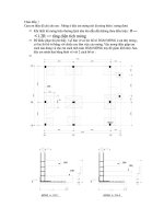
44.1
FUNDAMENTALS
OF
COMBUSTION
44.1.1
Air-Fuel Ratios
Combustion
is
rapid oxidation, usually
for the
purpose
of
changing chemical energy
into
thermal
energy—heat.
This energy usually
comes
from
oxidation
of
carbon, hydrogen,
sulfur,
or
compounds
containing
C, H,
and/or
S. The
oxidant
is
usually
O2—molecular
oxygen
from
the
air.
The
stoichiometry
of
basic chemical equation balancing permits determination
of the air
required
to
burn
a
fuel.
For
example,
1CH4
+
202
—
1CO2
+
2H2O
where
the
units
are
moles
or
volumes; therefore,
1
ft3
of
methane
(CH4)
produces
1
ft3
of
CO2;
or
1000
m3
CH4
requires
2000
m3
O2
and
produces
2000
m3
H2O.
Knowing
that
the
atomic weight
of
C is 12, H is 1, N is 14, O is 16, and S is 32,
it
is
possible
to use the
balanced chemical equation
to
predict
weight
flow
rates:
16
Ib/hr
CH4
requires
64
Ib/hr
O2
to
burn
to 44
Ib/hr
CO2
and 36
lb/
hr
H2O.
If
the
oxygen
for
combustion
comes
from
air,
it is
necessary
to
know
that
air is
20.99%
O2
by
volume
and
23.20%
O2
by
weight,
most
of the
remainder being nitrogen.
It
is
convenient
to
remember
the
following
ratios:
air/02
-
100/20.99
=
4.76
by
volume
N2/O2
=
3.76
by
volume
air/02
-
100/23.20
-
4.31
by
weight
N2/O2
-
3.31
by
weight
Rewriting
the
previous formula
for
combustion
of
methane,
1CH4
+
2O2
4-
2(3.76)N2
—
1CO2
+
2H2O
+
2(3.76)N2
or
1CH4
+
2(4.76)air
—>
1CO2
+
2H2O
+
2(3.76)N2
Table
44.1
lists
the
amounts
of air
required
for
stoichiometric
(quantitatively
and
chemically
Mechanical
Engineers'
Handbook,
2nd
ed., Edited
by
Myer
Kutz.
ISBN
0-471-13007-9
©
1998
John
Wiley
&
Sons, Inc.
CHAPTER
44
COMBUSTION
Richard
J.
Reed
North
American
Manufacturing
Company
Cleveland,
Ohio
44.1
FUNDAMENTALS
OF
COMBUSTION
1431
44.1.1
Air-Fuel
Ratios
1431
44.1.2
Fuels
1433
44.2
PURPOSES
OF
COMBUSTION
1435
44.3
BURNERS
1439
44.3.1
Burners
for
Gaseous
Fuels
1439
44.3.2
Burners
for
Liquid Fuels
1441
44.4
SAFETY CONSIDERATIONS 1442
44.5
OXY-FUEL
FIRING
1447
Table
44.1 Proper Combining Proportions
for
Perfect
Combustion3
m3
air
kg
fuel
10.8
10.8
12.6
9.39
2.01
13.1
28.2
4.97
14.1
10.6
12.4
12.8
12.1
3.52
m2O2
kg
fuel
2.28
2.28
2.65
1.97
0.422
2.76
5.92
1.04
2.96
2.22
2.60
2.69
2.54
0.74
ft3
air
Ib
fuel
174
174
203
150
32.2
210
451
79.5
226
169
198
205
193
56.4
ft3O2
Ib
fuel
36.5
36.5
42.5
31.6
6.76
44.2
94.7
16.7
47.4
35.5
41.6
43.1
40.6
11.8
wt
air
wt
fuel
13.3
13.3
15.5
11.5
2.46
16.1
34.5
6.08
17.2
12.9
15.1
15.7
14.8
4.31
wtO2
wt
fuel
3.08
3.08
3.59
2.67
0.571
3.73
8.00
1.41
4.00
3.00
3.51
3.64
3.43
1.00
vol
air
vol
fuel
11.9
35.7
31.0
2.38
16.7
2.38
7.15
9.53
23.8
21.4
vol
O2
vol
fuel
2.50
7.50
6.50
0.50
3.50
0.50
1.50
2.00
5.00
4.50
Fuel
Acetylene,
C2H2
Benzene,
C6H6
Butane,
C4H10
Carbon,
C
Carbon monoxide,
CO
Ethane,
C2H6
Hydrogen,
H2
Hydrogen
sulfide,
H2S
Methane,
CH4
Naphthalene,
C10H8
Octane,
C8H18
Propane,
C3H8
Propylene,
C3H6
Sulfur,
S
a
Reproduced
with
permission
from Combustion
Handbook.1
(See Ref.
1)
correct)
combustion
of a
number
of
pure
fuels,
calculated
by the
above
method.
(Table
46.
Ic
lists
similar
information
for
typical
fuels
that
are
mixtures
of
compounds,
calculated
by the
above method,
but
weighted
for the
percentages
of the
various
compounds
in the
fuels.)
The
stoichiometrically
correct
(perfect, ideal)
air/fuel
ratio
from
the
above formula
is
therefore
2 +
2(3.76)
=
9.52 volumes
of
air
per
volume
of the
fuel
gas.
More
than
that
is
called
a
"lean"
ratio,
and
includes excess
air and
produces
an
oxidizing atmosphere.
For
example,
if the
actual
air/
fuel
ratio
were
10:1,
the
%excess
air
would
be
1°^
X
100
-
5.04%
Communications
problems
sometimes
occur because
some
people think
in
terms
of
air/fuel
ratios,
others
in
fuel/air
ratios;
some
in
weight
ratios,
others
in
volume
ratios;
and
some
in
mixed
metric
units
(such
as
normal cubic meters
of air per
metric tonne
of
coal), others
in
mixed
American
units
(such
as
ft3
air/gal
of
oil).
To
avoid such confusions,
the
following
method
from
Ref.
1 is
recommended.
It
is
more
convenient
to
specify
air/fuel
ratio
in
unitless
terms such
as
%air
(%aeration),
%excess
air,
%deficiency
of
air,
or
equivalence
ratio.
Those
experienced
in
this
field
prefer
to
converse
in
terms
of
%excess
air.
The
scientific
community
favors equivalence
ratio.
The
%air
is
easiest
to use
and
explain
to
newcomers
to the
field:
"100%
air"
is the
correct (stoichiometric) amount; 200%
air
is
twice
as
much
as
necessary,
or
100% excess air.
Equivalence
ratio,
widely used
in
combustion
research,
is the
actual
amount
of
fuel
expressed
as a
fraction
percent
of the
stoichiometrically
correct
amount
of
fuel.
The
Greek
letter
phi,
4>,
is
usually used:
4>
= 0.9 is
lean;
<|>
=
1.1 is
rich;
and
4>
—
1.0 is
"on-ratio."
Formulas
relating
%air,
4>,
%excess
air
(%XS),
and
%deficiency
of
air
(%def)
are
%air
-
100/cf>
= %XS + 100
=
100 -
%def
100 1
* ~ %XS + 100 ~ 1 -
(%def/100)
%XS
-
%air
-
100
-
——
X 100
$
%def
= 100 -
%air
-
^—
x 100
4>
Table 44.2
lists
a
number
of
equivalent terms
for
convenience
in
converting values
from
one
"language"
to
another.
Excess
air is
undesirable, because,
like
N2,
it
passes through
the
combustion process without
chemical reaction;
yet it
absorbs heat, which
it
carries
out the flue. The
percent
available
heat (best
possible
fuel
efficiency)
is
highest with zero excess air. (See Fig.
44.1.)
Excess
fuel
is
even
more
undesirable because
it
means
there
is a
deficiency
of air and
some
of
the
fuel
cannot
be
burned. This
results
in
formation
of
soot
and
smoke.
The
accumulation
of
unburned
fuel
or
partially
burned
fuel
can
represent
an
explosion hazard.
Enriching
the
oxygen content
of the
combustion "air" above
the
normal 20.9% reduces
the
nitrogen
and
thereby reduces
the
loss
due to
heat
carried
up the
stack. This
also
raises
the flame
temperature,
improving heat
transfer,
especially
that
by
radiation.
Vitiated
air
(containing
less
than
the
normal 20.9%
oxygen)
results
in
less
fuel
efficiency,
and
may
result
in flame
instability.
Vitiated
air is
sometimes
encountered
in
incineration
of
fume
streams
or
in
staged combustion,
or
with
flue gas
recirculation.
44.1.2
Fuels
Fuels used
in
practical
industrial
combustion processes have such
a
major
effect
on the
combustion
that
they must
be
studied
simultaneously with combustion. Fuels
are
covered
in
detail
in
later
chap-
ters,
so the
treatment here
is
brief,
relating
only
to the
aspects having
direct
bearing
on the
combustion
process.
Gaseous
fuels
are
generally
easier
to
burn, handle,
and
control than
are
liquid
or
solid
fuels.
Molecular mixing
of a
gaseous
fuel
with oxygen need
not
wait
for
vaporization
nor
mass
transport
within
a
solid.
Burning
rates
are
limited only
by
mixing
rates
and the
kinetics
of the
combustion
reactions;
therefore, combustion
can be
compact
and
intense. Reaction times
as
short
as
0.001
sec
and
combustion volumes
from
104
to
107
Btu/hr
•
ft3
are
possible
at
atmospheric
pressure.2
Gases
of low
calorific
value
may
require such
large
volumes
of air
that
their
combustion
rates
will
be
limited
by the
mixing time.
Combustion
stability
means
that
a flame
lights
easily
and
then burns
steadily
and
reliably
after
the
pilot
(or
direct
spark)
is
programmed
off.
Combustion
stability
depends
on
burner geometry,
plus
Fuel
rich
(air
lean)
Stoiehiometric
Fuel
lean
(air
rich)
*
2.50
1.67
1.25
1.11
1.05
1.00
0.95
0.91
0.83
0.78
0.71
0.62
0.56
0.50
0.40
0.33
0.25
0.20
0.167
0.091
0.048
%air
40
60
80
90
95
100
105
110
120
130
140
160
180
200
250
300
400
500
600
1100
2100
%def
60
40
20
10
5
0
%xs
0
5
10
20
30
40
60
80
100
150
200
300
400
500
1000
2000
Fig.
44.1 Percent
available
heat (best possible
efficiency)
peaks
at
Stoiehiometric
air/fuel
ratio.1
Table
44.2 Equivalent
Ways
to
Express
Fuel-to-Air
or
Air-to-Fuel
Ratios1
air
and
fuel
flow
controls
that
maintain
the
point(s)
of flame
initiation
(a)
above
the
fuel's
minimum
ignition
temperature,
(b)
within
the
fuel's
flammability
limits,
and (c)
with feed speed equal
to flame
speed—throughout
the
burner's
full
range
of
firing
rates
and
conditions.
(Fuel
properties
are
discussed
and
tabulated
in
Chapters
46 and
47.)
Liquid fuels
are
usually
not as
easily
burned,
handled,
or
controlled
as are
gaseous
fuels.
Mixing
with
oxygen
can
occur only
after
the
liquid fuel
is
evaporated; therefore, burning
rates
are
limited
by
vaporization rates.
In
practice,
combustion
intensities
are
usually
less
with
liquid
fuels
than with
high
calorific
gaseous
fuels such
as
natural gas.
Because
vaporization
is
such
an
integral part
of
most
liquid fuel burning processes,
much
of the
emphasis
in
evaluating liquid fuel properties
is on
factors
that
relate
to
vaporization, including vis-
cosity,
which
hinders
good
atomization,
the
primary
method
for
enhancing vaporization.
Much
con-
cern
is
also devoted
to
properties
that
affect storage
and
handling because, unlike gaseous fuels
that
usually
come
through
a
public
utility's
mains,
liquid fuels
must
be
stored
and
distributed
by the
user.
The
stability
properties (ignition temperature,
flammability
limits,
and flame
velocity)
are not
readily
available
for
liquid fuels,
but flame
stability
is
often
less
critical
with liquid fuels.
Solid fuels
are
frequently
more
difficult
to
burn, handle,
and
control than liquid
or
gaseous
fuels.
After
initial
volatilization,
the
combustion
reaction
rate
depends
on
diffusion
of
oxygen
into
the
remaining
char particle,
and the
diffusion
of
carbon
monoxide
back
to its
surface,
where
it
burns
as
a
gas. Reaction rates
are
usually
low and
required
combustion
volumes
high, even with pulverized
solid
fuels
burned
in
suspension.
Some
fluidized bed and
cyclone
combustors
have been reported
to
reach
the
intensities
of gas and oil flames.2
Most
commonly
measured
solid
fuel properties apply
to
handling
in
stokers
or
pulverizers.
See
Chapter
48.
Wastes,
by-product fuels,
and
gasified solids
are
being used
more
as
fuel costs
rise.
Operations
that
produce
such materials should attempt
to
consume
them
as
energy sources.
Handling
problems,
the
lack
of a
steady supply,
and
pollution
problems
often complicate such fuel usage.
For the
precise temperature control
and
uniformity required
in
many
industrial heating processes,
the
burning
of
solids, especially
the
variable quality solids
found
in
wastes, presents
a
critical
problem.
Such
fuels
are
better
left
to
very large
combustion
chambers,
particularly boilers.
When
solids
and
wastes
must
be
used
as
heat sources
in
small
and
accurate heating processes,
a
better approach
is to
convert
them
to
low-Btu
(producer)
gas,
which
can be
cleaned
and
then controlled
more
precisely.
44.2
PURPOSES
OF
COMBUSTION
The
purposes
of
combustion,
for the
most
part, center
around
elevating
the
temperature
of
something.
This includes
the first
step
in all
successive
combustion
processes—the
pilot
flame—and,
similarly,
the
initiation
of
incineration. Elevating
the
temperature
of
something
can
also
make
it
capable
of
transmitting
light
or
thermal
energy
(radiation
and
convection heat transfer),
or
it
can
cause
chemical
dissociation
of
molecules
in the
products
of
combustion
to
generate
a
special
atmosphere
gas for
protection
of
materials
in
industrial heat processing.
All of the
above
functions
of
combustion
are
minor
in
comparison
to the
heating
of
air, water
and
steam,
metals, nonmetallic minerals,
and
organics
for
industrial
processing,
and for
space
comfort
conditioning.
For all of
these,
it is
necessary
to
have
a
workable
method
for
evaluating
the
heat
available
from
a
combustion
process.
Available heat
is the
heat accessible
for the
load (useful output)
and to
balance
all
losses other
than stack losses. (See Fig.
44.2.)
The
available heat
per
unit
of
fuel
is
AH = HHV -
total
stack
gas
loss
= LHV - dry
stack
gas
loss
%
available heat
-
100(AH/HHV)
where
AH =
available heat,
HHV =
higher heating value,
and LHV =
lower
heating value,
as
defined
in
Chapter
47.
Figure
44.3
shows
values
of %
available heat
for a
typical natural gas; Fig.
44.4
for a
typical residual oil;
and
Fig. 53.2
in
Chapter
53, for a
typical
distillate
oil.
Example
44.1
A
process furnace
is to
raise
the
heat content
of
10,000
Ib/hr
of a
load
from
0 to 470
Btu/lb
in a
continuous furnace
(no
wall storage) with
a flue gas
exit
temperature
of
1400°F.
The sum of
wall
loss
and
opening
loss
is
70,000
Btu/hr.
There
is no
conveyor
loss. Estimate
the
fuel
consumption
using
1000
Btu/ft3
natural
gas
with
10%
excess air.
Solution:
From
Fig.
44.3,
%
available heat
=
58.5%.
In
other
words,
the flue
losses
are
100%
-
58.5%
=
41.5%.
The sum of
other losses
and
useful output
=
70,000
+
(10,000)(470)
=
4,770,000
Btu/hr.
This
constitutes
the
"available heat" required.
The
required gross input
is
therefore
4,770,000/0.585
-
8,154,000
Btu/hr,
of
8154
ft3/hr
of
natural
gas
(and about
81.540
ft3/hr
of
air).
The use of the
above
precalculated
%
available heats
has
proved
to be a
practical
way to
avoid
long
iterative
methods
for
evaluating stack losses
and
what
is
therefore
left
for
useful heat output
Fig.
44.2
Sankey
diagram
for a
furnace, oven,
kiln,
incinerator,
boiler,
or
heater—a
qualitative
and
roughly
quantitative
method
for
analyzing efficiency
of
fuel-fired
heating equipment.
and to
balance other losses.
For low
exit
gas
temperatures such
as
encountered
in
boilers, ovens,
and
dryers,
the dry
stack
gas
loss
can be
estimated
by
assuming
the
total
exit
gas
stream
has the
specific
heat
of
nitrogen,
which
is
usually
a
major
component
of the poc
(products
of
combustion).
dry
stack
loss
_
/lb
dry
poc\
/
0.253
Btu
\
unit
of
fuel
~
\
unit
fuel
/
\lb
poc
(°F)/
exit
or
/scf
dry
proc\
/
0.0187
Btu
\
_
\
unit
fuel
/
\scf
poc
(°F)/
For a
gaseous
fuel,
the
"unit fuel"
is
usually
scf
(standard cubic foot),
where
"standard"
is at
29.92
in.
Hg
and
60°F
or
nm3
(normal
cubic
meter),
where
"normal"
is at
1.013
bar and
15°C.
Heat
transferred
from
combustion takes
two
forms:
radiation
and
convection.
Both
phenomena
involve
transfer
to a
surface.
Flame
radiation
comes
from
particle
radiation
and gas
radiation.
The
visible
yellow-orange
light
normally associated with
a flame is
actually
from
solid
soot
or
char
particles
in the flame, and the
"working"
portion
of
this
form
of
heat transfer
is in the
infrared wavelength range.
Because
oils
have higher
C/H
ratios
than gaseous fuels,
oil flames are
usually
more
yellow than
gas flames
(although
oil
flames
can be
made
blue).
Gas flames can be
made
yellow,
by a
delayed-mixing
burner
design,
for the
purpose
of
increasing
their
radiating capability.
Particulate
radiation
follows
the
Stefan-Boltzmann
law for
solids,
but
depends
on the
concentration
of
particles
within
the flame.
Estimating
or
measuring
the
particle
temperature
and
concentration
is
difficult.
Gas
radiation
and
blue
flame
radiation contain
more
ultraviolet
radiation
and
tend
to be
less
intense.
Triatomic
gases
(CO2,
H2O,
and
SO2)
emit radiation
that
is
largely
invisible.
Gases
beyond
the
tips
of
both luminous
and
nonluminous
flames
continue
to
emit
this
gas
radiation.
As a
very
broad generalization, blue
or
nonluminous
flames
tend
to be
hotter,
smaller,
and
less
intense radiators
than
luminous
flames. Gas
radiation depends
on the
concentrations
(or
partial
pressures)
of the
triatomic
molecules
and the
beam
thickness
of
their
"cloud."
Their temperatures
are
very transient.
Fig.
44.3
Available
heat
for
1000
Btu/ft3
natural
gas.
Examples:
In a
furnace
with
1600°F
flue
temperature,
60°F
air,
and 10%
excess
air,
read
that
54% of the
gross
heat
input
is
available
for
heating
the
load
and
balancing
the
losses other than stack losses; and,
at the
x-intercept,
read
that
the
adiabatic
flame temperature
will
be
3310°F.
If
the
combustion
air
were
1200°F
instead
of
60°F,
read
that
the
available
heat would
be 77% and
that
the
adiabatic
flame temperature would
be
3760°F
It
is
enlightening
to
compare
this
graph
with
Fig.
44.16
for
oxy-fuel
firing
and
oxygen
enrightment.
Fig.
44.4
Available
heat
for
153,120 gross
Btu/gal
residual
fuel
oil
(heavy,
No. 6).
With
2200°F
gases
leaving
a
furnace,
1000°F
air
entering
the
burners,
and 10%
excess
air,
62% of
the
153,120
is
available;
100%
- 62% = 38%
is
stack loss.
Fig.
44.5
Open,
natural
draft-type burner.
Convection
from
combustion
produces
beyond
the flame tip
follows conventional convection
formulas—largely
a
function
of
velocity. This
is the
reason
for
recent emphasis
on
high-velocity
burners.
Flame
convection
by
actual
flame
impingement
is
more
difficult
to
evaluate because
(a)
flame
temperatures change
so
rapidly
and are so
difficult
to
measure
or
predict,
and (b)
this
involves
extrapolating
many
convection formulas
into
ranges
where
good
data
are
lacking.
Refractory radiation
is a
second stage
of
heat transfer.
The
refractory
must
first be
heated
by
flame
radiation
and/or convection.
A gas
mantle, so-called "infrared" burners,
and
"radiation burn-
ers"
use flame
convection
to
heat
some
solid
(refractory
or
metal)
to
incandescence
so
that
they
become
good
radiators.
44.3
BURNERS
In
some
cases,
a
burner
may be
nothing
more
than
a
nozzle.
Some
would
say
it
includes
a
mixing
device,
windbox,
fan,
and
controls.
In
some
configurations,
it is
difficult
to say
where
the
burner
ends
and the
combustion
chamber
or
furnace begins.
In
this
section,
the
broadest sense
of the
terms
will
generally
be
used.
A
combustion
system provides
(1)
fuel,
(2)
air,
(3)
mixing,
(4)
proportioning,
(5)
ignition,
and
(6) flame
holding.
In the
strictest
sense,
a
burner does only function
6; in the
broadest sense,
it
may
do any or all of
these functions.
44.3.1
Burners
for
Gaseous
Fuels
Open
and
natural draft-type burners
rely
on a
negative pressure
in the
combustion
chamber
to
pull
in
the air
required
for
combustion, usually through adjustable
shutters
around
the
fuel
nozzles.
The
suction
in the
chamber
may be
natural
draft
(chimney
effect)
or
induced
draft
fans.
A
crude
"burner"
may be
nothing
more
than
a gas gun
and/or
atomizer inserted through
a
hole
in the
furnace wall.
Fuel-air mixing
may be
poor,
and
fuel-air
ratio
control
may be
nonexistent.
Retrofitting
for
addition
of
preheated combustion
air is
difficult.
(See
Fig.
44.5.)
Sealed-in
and
power
burners have
no
intentional
"free"
air
inlets
around
the
burner,
nor are
there
air
inlets
in the
form
of
louvers
in the
combustion
chamber
wall.
All air
in-flow
is
controlled, usually
by a
forced
draft
blower
or fan
pushing
the air
through pipes
or a
windbox.
These
burners usually have
a
higher
air
pressure drop
at the
burner,
so air
velocities
are
higher,
enabling
more
through mixing
and
better
control
of flame
geometry.
Air flow can be
measured,
so
automatic air-fuel
ratio
control
is
easy.
(See
Fig.
44.6.)
Windbox
burners often consist
of
little
more
than
a
long atomizer
and a gas gun or gas
ring.
These
are
popular
for
boilers
and air
heaters
where
economic
reasons have
dictated
that
the
required
large
volumes
of air be
supplied
at
very
low
pressure
(2-10
in.
we)
(in.
we
=
inches
of
water
column).
Precautions
are
necessary
to
avoid
fuel
flowback
into
the
windbox.
(See
Fig.
44.7.)
Fig.
44.6
Sealed-in,
power
burner.
Fig.
44.7
Windbox
burner.
Packaged
burners usually consist
of
bolt-on arrangements with
an
integral
fan and
perhaps
integral
controls.
These
are
widely used
for new and
retrofit
installations
from
very small
up to
about
50 X
106
Btu/hr.
(See Fig.
44.8.)
Premix
burner systems
may be
found
in any of the
above configurations.
Gas and air are
thor-
oughly
mixed
upstream
of the flame-holding
nozzle.
Most
domestic appliances incorporate premixing,
using
some
form
of gas
injector
or
inspirator (gas pressure inducing
air
through
a
venturi).
Small
industrial
multiport
burners
of
this
type
facilitate
spreading
a
small
amount
of
heat over
a
large area,
as
for
heating
kettles,
vats,
rolls,
small boilers,
moving
webs,
and
low-temperature processing
of
conveyorized
products. (See Fig.
44.9.)
Large
single port
premix
burners have been replaced
by
nozzle-mix burners. Better fuel-air
ratio
control
is
possible
by use of
aspirator
mixers. (Air injection
provides
the
energy
to
draw
in the
proper proportion
of
gas.) (See Fig.
44.10.)
Many
small
units
have undersized blowers, relying
on
furnace
draft
to
provide secondary air.
As
fuel
costs
rise,
the
unwarranted excess
air
involved
in
such arrangements
makes
them
uneconomical.
Larger than
a
4-in.
(100-mm)
inside-diameter mixture manifold
is
usually considered
too
great
an
explosion
risk. For
this
reason, mixing
in a fan
inlet
is
rarely used.
Nozzle-mix
burner systems
constitute
the
most
common
industrial
gas
burner arrangement today.
Gas and air are
mixed
as
they enter
the
combustion
chamber
through
the flame
holder. (See Fig.
44.11.)
They
permit
a
broad range
of
fuel-air
ratios,
a
wide
variety
of flame
shapes,
and
multifuel
firing. A
very
wide
range
of
operating conditions
are now
possible with
stable
flames,
using nozzle-
mix
burners.
For
processes requiring special atmospheres, they
can
even operate with very
rich
(50%
excess fuel)
or
lean
(1500%
excess air).
They
can be
built
to
allow very high
velocities
(420,000
scfh/in.2
of
refractory nozzle
opening)
for
emphasizing
convection heat transfer. (See Fig.
44.12.)
Others
use
centrifugal
and
coanda
effects
to
cause
the flame to
scrub
an
adjacent refractory wall
contour, thus enhancing wall radiation. (See Fig.
44.13.)
By
engineering
the
mixing
configuration,
nozzle-mix burner designers
are
able
to
provide
a
wide
range
of
mixing
rates,
from
a
fast,
intense
ball
of flame
(L/D
= 1) to
conventional
feather-shaped
flame
(L/D
=
5-10)
to
long
flames
(L/D
=
20-50).
Changeable
flame
patterns
are
also possible.
Delayed-mix
burners
are a
special
form
of
nozzle mix,
in
which
mixing
is
intentionally slow.
(A
raw gas
torch
is an
unintentional
form
of
delayed
mixing.)
Ignition
of a
fuel with
a
shortage
of air
results
in
polymerization
or
thermal cracking
that
forms
soot
particles
only
a few
microns
in
diameter.
These
solids
in the flame
absorb heat
and
glow
immediately, causing
a
delayed
mix flame to be
yellow
or
orange.
The
added luminosity enhances
flame
radiation heat transfer,
which
is one of the
reasons
for
using
delayed-mix
flames. The
other reason
is
that
delayed mixing permits stretching
the
heat
release over
a
great
distance
for
uniform
heating
down
the
length
of a
radiant tube
or a
long
kiln
or
furnace
that
can
only
be fired
from
one
end.
Fuel-Directed
Burners
Most
industrial
process burners have
traditionally
used energy
from
the air
stream
to
maintain
flame
stability
and flame
shape.
Now
that
most
everyone
has
access
to
higher-pressure
fuel
supplies,
it
Fig.
44.8
Integral
fan
burner.
Fig.
44.9
Premix burners with
inspirator
mixer.
makes
sense
to use the
energy
in the
fuel
stream
for
controlling
flame
stability
and
shape, thereby
permitting
use of
lower pressure
air
sources.
Figure
44.14
shows
a
fuel-directed burner
for gas and
preheated air. Multiple supply passages
and
outlet
port positions permit changing
the flame
pattern during operation
for
optimum
heat
transfer
during
the
course
of a
furnace cycle.
Oil
burners
or
dual-fuel combination burners
can be
constructed
in
a
similar
manner
using two-fluid atomizers with
compressed
air or
steam
as the
atomizing
medium.
44.3.2
Burners
for
Liquid
Fuels
Much
of
what
has
been
said above
for gas
burners applies
as
well
for oil
burning. Liquids
do not
burn; therefore, they
must
be
vaporized
first.
Kettle boiling
or hot air can be
used
to
produce
a hot
vapor stream
that
is
directly
substitutable
for gas in
premix
burners. Unless there
are
many
burners
or
they
are
very small,
it is
generally
more
practical (less
maintenance)
to
convert
to
combination
(dual-fuel) burners
of the
nozzle-mix
type.
Vaporization
by
Atomization
Almost
all
industrial
liquid
fuel burners
use
atomization
to aid
vaporization
by
exposing
the
large
surface area (relative
to
volume)
of
millions
of
droplets
in the
size range
of
100-400
jim.
Mass
transfer
then occurs
at a
rapid
rate
even
if the
droplets
are not
exposed
to
furnace radiation
or hot
air.
Pressure atomization
(as
with
a
garden
hose)
uses
the
pressure energy
in the
liquid
steam
to
cause
the
kinetic energy
to
overcome
viscous
and
surface tension forces.
If
input
is
turned
down
by
reducing
fuel
pressure,
however,
atomizing quality suffers; therefore,
this
method
of
atomization
is
limited
to
on-off
units
or
cases
where
more
than
250 psi
fuel pressure
is
available.
Two-fluid
atomization
is the
method
most
commonly
used
in
industrial
burners. Viscous
friction
by a
high-velocity
second
fluid
surrounding
the
liquid fuel stream
literally
tears
it
into droplets.
The
second
fluid may be
low-pressure
air (<2
psi,
or
<13.8
kPa),
compressed
air, gaseous fuel,
or
steam.
Many
patented atomizer designs
exist—for
a
variety
of
spray angles, sizes,
turndown
ranges, droplet
sizes.
Emulsion
mixing
usually gives superior atomization
(uniformly
small drops with
relatively
small
consumption
of
atomizing
medium)
but
control
is
complicated
by
interaction
of the
pressures
and flows of the two
streams. External
mixing
is
just
the
opposite.
A
compromise
called tip-emulsion
atomization
is the
current
state
of the
art.
Rotary-cup atomization delivers
the
liquid
fuel
to the
center
of a
fast
spinning
cup
surrounded
by an air
stream. Rotational speed
and air
pressure determine
the
spray angle. This
is
still
used
in
some
large boilers,
but the
moving
parts
near
the
furnace heat have proved
to be too
much
of a
maintenance
problem
in
higher-temperature process furnaces
and on
smaller
installations
where
a
strict
preventive maintenance
program
could
not be
effected.
Sonic
and
ultrasonic atomization systems create very
fine
drops,
but
impart very
little
motion
to
them.
For
this
reason they
do not
work
well with conventional burner configurations,
but
require
an
all
new
design.
Fig.
44.10
Premix burners with aspirator mixer.
Fig.
44.11
Air-directed
nozzle-mix burner.
Liquid
Fuel Conditioning
A
variety
of
additives
can be
used
to
reduce
fuel
degeneration
in
storage,
minimize
slagging, lessen
surface
tension, reduce
pollution,
and
lower
the dew
point. Regular tank draining
and
cleaning
and
the
use of
filters
are
recommended.
Residual
oils
must
be
heated
to
reduce
their
viscosity
for
pumping,
usually
to 500 SSU
(100
cSt).
For
effective
atomization, burner manufacturers specify
viscosities
in the
range
of
100-150
SSU
(22-32
cSt).
In all but
tropic
climates, blended
oils
(Nos.
4 and 5)
also require heating.
In
Arctic
situations,
distillate
oils
need heating. Figure
44.15
enables
one to
predict
the oil
temperature nec-
essary
for a
specified
viscosity.
It is
best,
however,
to
install
extra heating capacity because delivered
oil
quality
may
change.
Oil
heaters
can be
steam
or
electric.
If oil flow
stops,
the oil may
vaporize
or
char. Either reduces
heat
transfer
from
the
heater surfaces,
which
can
lead
to
catastrophic
failure
in
electric
heaters.
Oil
must
be
circulated through heaters,
and the
system
must
be
fitted
with protective
limit
controls.
Hot
oil
lines
must
be
insulated
and
traced with steam, induction,
or
resistance
heating.
The
purpose
of
tracing
is to
balance heat
loss
to the
environment. Rarely
will
a
tracing system have
enough
capacity
to
heat
up an oil
line
from
cold.
When
systems
are
shut
down,
arrangements
must
be
made
to
purge
the
heavy
oil
from
the
lines
with steam, air,
or
(preferably)
distillate
oil.
Oil
standby systems
should
be
operated regularly, whether needed
or
not.
In
cold climates, they should
be
started
before
the
onset
of
cold weather
and
kept
circulating
all
winter.
44.4 SAFETY CONSIDERATIONS
Operations involving combustion
must
be
concerned about
all the
usual
safety
hazards
of
industrial
machinery, plus explosions,
fires,
burns
from
hot
surfaces,
and
asphyxiation. Less immediately severe,
but
long-range health problems
related
to
combustion
result
from
overexposure
to
noise
and
pollutants.
Preventing explosions should
be the
primary operating
and
design concern
of
every person
in any
way
associated
with combustion operations, because
an
explosion
can be so
devastating
as to
elim-
inate
all
other goals
of
anyone
involved.
The
requirements
for an
explosion include
the first five
requirements
for
combustion (Table
44.3);
therefore,
striving
to do a
good
job of
combustion
may.
set
you up for an
explosion.
The
statistical
probability
of
having
all
seven explosion requirements
at
the
same
time
and
place
is so
small
that
people
become
careless,
and
therein
lies
the
problem.
Continuing
training
and
retraining
is the
only answer.
Fig.
44.12
High-velocity
burner.
Fig.
44.13 Wall
radiating
burner
(flat
flame
or
coanda
type).
The
lower
and
upper
limits
of flammability are the
same
as the
lower
and
upper explosive
limits
for
any
combustible
gas or
vapor. Table 46.3
lists
these values
for
gases. Table 44.4
lists
similar
information
for
some
common
liquids.
References
3, 4, and 5
list
explosion-related data
for
many
industrial
solvents
and
off-gases.
Electronic
safety
control programs
for
most
industrial
combustion systems
are
generally designed
(a) to
prevent accumulation
of
unburned
fuel
when
any
source
of
ignition
is
present
or (b) to im-
mediately
remove
any
source
of
ignition
when
something goes
wrong,
causing
fuel
accumulation.
Of
course,
this
is
impossible
in a
furnace operating above
1400°F.
If a
burner
in
such
a
furnace
should snuff
out
because
it
happened
to go too rich,
requirement
number
3 is
negated
and
there
can
be no
explosion
until
someone
(untrained) opens
a
port
or
shuts
off the
fuel.
The
only
safe
procedure
is
to
gradually
flood the
chamber
with steam
or
inert
gas
(gradually,
so as not to
change furnace
pressure
and
thereby cause
more
air
in-flow).
(a) The
best
way to
prevent unburned
fuel
accumulation
is to
have
a
reliable
automatic fuel-air
ratio
control system coordinated with automatic furnace pressure control
and
with
input
control
so
that
input cannot range beyond
the
capabilities
of
either
automatic system.
The
emergency back-up
system consists
of a
trip
valve
that
stops
fuel
flow in the
event
of flame
failure
or any of
many
other
interlocks
such
as low air flow, or
high
or low
fuel
flow.
(b)
Removal
of
ignition
sources
is
implemented
by
automatic
shutoff
of
other burner
flames,
pilot
flames,
spark
igniters,
and
glow
plugs.
In
systems
where
a
single
flame
sensor monitors
either
main
flame
or
pilot
flame, the
pilot
flame
must
be
programmed
out
when
the
main
flame is
proven.
If
this
is
not
done, such
a
"constant"
or
"standing"
pilot
can
"fool"
the flame
sensor
and
cause
an
explosion.
Most
codes
and
insuring
authorities
insist
on use of flame
monitoring devices
for
combustion
chambers
that
operate
at
temperatures
below
1400°F.
Some
of
these
authorities
point
out
that
even
high-temperature
furnaces must
go
through
this
low-temperature range
on
their
way to and
from
their
Fig.
44.14
Low
NOX
fuel-directed
gas
burner
for
use
with
preheated
air.
0
Increasing tangen-
tial
gas
flow (adjustment
screw
S)
shortens flame.
(2)
Increasing forward
gas
flow (adjustment
screw
L)
lengthens flame.
(3) Jet
gas—to
maintain
flame
definition
as
input
is
reduced. (Cour-
tesy
of
North American Mfg.
Company.)
Fig.
44.15 Viscosity-temperature
relations
for
typical
fuel
oils.
Table 44.3
Requirements
for
Combustion,
Useful
Combustion,
and
Explosion3
Requirements
for
Combustion
1.
Fuel
2.
Oxygen
(air)
3.
Proper proportion
(within
flammability
limits)
4.
Mixing
5.
Ignition
Requirements
for
Useful
Combustion
1.
Fuel
2.
Oxygen
(air)
3.
Proper proportion
(within
flammability
limits)
4.
Mixing
5.
Ignition
6.
Flame
holder
Requirements
for
Explosion
1.
Fuel
2.
Oxygen
(air)
3.
Proper proportion
(within explosive limits)
4.
Mixing
5.
Ignition
6.
Accumulation
7.
Confinement
a
There
have been incidents
of
disastrous explosions
of
unconfined
fast-burning gases,
but
most
of
the
damage
from
industrial
explosions
comes
from
the
fragments
of the
containing furnace
that
are
propelled
like
shrapnel. Lightup explosions
are
often only
"puffs"
if
large doors
are
kept
open
during
startup.
Table
44.4
Flammability
Data
for
Liquid Fuels
Boiling
Temperature,
°F
(°C)
Vapor
density,
G(air
= 1)
Autoignition
Temperature,
°F
(°C)
Flammability
Limits
(%)
Volume
in Air
Lower
Upper
Flash
Point,
°F
(°C)
(Closed
Cup
Method)
Liquid
Fuel
31
(-1)
11
(-12)
173
(78)
203
(95)
340-555
(171-291)
<590
<310
340-640
(171-338)
380-650 (193-343)
425-760 (218-404)
91-403
(33-206)
107-319
(42-159)
140-490
(60-254)
370-530
(188-277)
250-500 (121-260)
350-550
(177-288)
147
64
167 75
300-400
(149-204)
200-300 (93-149)
303
(151)
190-250
(88-121)
-44
(-42)
-54
(-48)
2.06
2.06
1.59
3-4
3-4
4.5
1.11
3.75
4.41
3.93
1.56
1.49
761
(405)
864
(462)
737
(392)
445-560 (229-293)
350-625
(177-329)
500-705
(260-374)
490-545 (254-285)
505
(263)
765
(407)
700
(371)
800-880 (427-471)
468
(242)
400
(204)
500
(260)
440-560 (227-293)
878
(470)
440-500
(227-260)
450-500
(232-260)
403
(206)
784
(418)
871
(466)
927-952 (497-511)
1.9
8.5
1.8
8.4
3.5 19
3.6 10
0.6 5.6
1.3
6.0
1.3
6.0
1
5
1
5
1
5
1.3-1.4
6.0-7.6
1
6.0-7.6
0.8
6.2
0.6
4.6
0.6 5.6
5.5
36.5
0.8 5.0
0.9
6.0
0.74
2.9
1.0
6.0
2.2
9.6
2.0
11.1
-76
(-60)
-117
(-83)
55
(13)
85
(29)
114-185
(46-85)
>100
(>38)
126-230
(52-110)
MOO >38
154-240 (68-116)
130-310
(54-154)
150-430
(66-221)
-50±
(-46±)
-50±
(-46±)
-2
(-19)
105
(41)
127
(53)
110-130
(43-54)
54
(12)
75
(24)
100-110
(38-43)
20-45
(-7-+7)
88
(31)
10
(-12)
-156
(-104)
-162 (-108)
Butane,
-n
Butane, -iso
Ethyl alcohol
(ethanol)
Ethyl alcohol,
30% in
water
Fuel oil,
#1
Fuel
oil
(diesel),#l-D
Fuel oil,
#2
Fuel
oil
(diesel),
#2-D
Fuel oil,
#4
Fuel oil,
#5
Fuel oil,
#6
Gasoline, automotive
Gasoline,
aviation
Jet
fuel,
JP-4
Jet
fuel,
JP-5
Jet
fuel,
JP-6
Kerosene
Methyl
alcohol
(methanol)
Methyl
alcohol,
30% in
water
Naphtha,
dryclean
Naphtha,
76%,
vm&p
Nonane,
-n
Octane, -iso
Propane
Propylene
Flue
Gas
Exit
Temperature,
F
Fig.
44.16
Percents
available
heat
for Phi
=
.95 or 5%
excess
air
with
average
natural
gas,
HHV =
1025
Btu/cu
ft,
with various
degrees
of
oxygen
enrichment
and for
oxy-fuel
firing
(top curve).
normal
operating temperature.
Another
situation
where
safety regulations
and
economic
reality
have
not
yet
come
to
agreement
involves
combustion
chambers
with
dozens
or
even
hundreds
of
burners,
such
as
refinery heaters,
ceramic
kilns,
and
heat-transfer furnaces.
Avoiding fuel-fed
fires first
requires preventing explosions,
which
often
start
such
fires.
(See pre-
vious discussion.)
Every
building containing
a
fuel-fired boiler,
oven,
kiln, furnace, heater,
or
incin-
erator
should have
a
spring-operated
manual
reset fuel
shutoff
valve outside
the
building with panic
buttons
at the
guardhouse
or at
exits
to
allow shutting
off
fuel
as one
leaves
the
burning building.
Gas-fuel lines should
be
overhead
where
crane
and
truck operators
cannot
rupture
them,
or
under-
ground.
If
underground,
keep
and use
records
of
their
locations
to
avoid digging accidents.
Overhead
fuel
lines
must
have
well-marked
manual
shutoff valves
where
they
can be
reached without
a
ladder.
Liquid-fuel
lines
should
be
underground;
otherwise,
a
rupture will
pour
or
spray fuel
on a fire.
The
greatest contributor
to
fuel-fed
fires is the
fuel shutoff valve
that
will
not
work.
All
such
valves,
manual
or
automatic,
must
be
tested
on a
regular
maintenance
schedule.
Such
testing
may
cause nuisance
shutdowns
of
related
equipment;
therefore,
a
practical
procedure
is to
have
the
main-
tenance
crew
do the
day's
end (or
week's
end)
shutdown
about
once
each
month.
The
same
test
can
check
for
leaking.
If it is a
fully
automatic
or
manual-reset automatic valve,
shutdown
should
be
accomplished
by
simulating
flame
failure and,
in
succession, each
of the
interlocks.
Because
so
much
depends
on
automatic fuel shutoff valves,
it
makes
sense
(a) to
have
a
backup
valve
(blocking
valve),
and (b) to
replace
it
before
it
hangs
up—at
least
every
5
years,
more
often
in
adverse
environments.
Maintenance
and
management
people
must
be
ever
alert
for
open
side panels
and
covers
on
safety
switches
and
fuel shutoff valves.
Remove
wedges,
wires,
or
blocks
that
are
holding
circuits
closed
or
valves
open.
Remove
jumper
wires unless
the
manufacturer's
wiring
diagram
specifies
that
they
be
left
in.
Eliminate valve by-passes unless they contain
a
similar valve.
Then,
get to the
root
of the
problem
by finding the
cause
of the
nuisance
that
caused
someone
to try to
bypass
the
safety
system.
Storage
of LP
gas,
oils,
or
solid fuels requires careful attention
to
applicable codes.
If the
point
of
use,
an
open
line,
or a
large leak
is
below
the oil
storage elevation, large quantities
may
siphon
out
and flow
into
an
area
where
there
is a
water heater
or
other source
of
ignition.
Steam
heaters
in
heavy
oil
tanks
need
regular inspections,
or
leaks
can
emulsify
the
oil, causing
an
overflow.
It is
advisable
to
make
provision
for
withdrawing
the
heater
for
repair without having
to
drain
the
whole
tank.
LP gas is
heavier than air.
Workers
have been suffocated
by
this
invisible
gas
when
it
leaked
into
access
pits
below
equipment.
Codes
and
regulations
are
proliferating,
many
by
local
authorities
or
insuring groups.
Most
refer,
as
a
base,
to
publications
of the
NFPA,
the
National Fire Protection Association,
Batterymarch
Park,
Quincy,
MA
02269.
Their publications usually represent
the
consensus
of
technically competent
volunteer
committees
from
industries
involved with
the
topic.
44.5
OXY-FUEL
FIRING
Commercially
"pure"
oxygen
(90-99%
oxygen)
is
sometimes
substituted
for air
(20.9%
oxygen),
(a) to
achieve higher
flame
temperature,
(b) to get
higher
%
available heat (best possible efficiency),
or
(c) to try to
eliminate nitrogen
from
the
furnace atmosphere,
and
thereby reduce
the
probability
of
NOX
pollution.
Figure
44.16
shows
percents available heat
and
adiabatic
flame
temperatures (x-intercepts)
for
various
amounts
of
oxygen
enrichment
of an
existing
air
supply,
and for
"oxy-fuel
firing".
The
latter
is
with
100%
oxygen,
and is the
only
way to use
oxygen
to
reduce
NOX;
oxygen
enrichment usually
causes
more
NOX.
Oxy-fuel burners have been water-cooled
in the
past,
but
their
propensity
to
spring leaks
and do
terrible
damage
has led to use of
better
materials
to
avoid water cooling.
Oxygen
burner nozzles
and
tiles
are
subject
to
much
higher temperatures
and
more
oxidizing atmospheres than
are air
burner
nozzles
and
tiles.
Control valves, regulators,
and
piping
for
oxygen
require
special
cleaning
and
material
selection.
REFERENCES
1.
R. J.
Reed
(ed.),
Combustion
Handbook,
Vol.
I, 3rd
Edition.
North
American
Mfg. Co.,
Cleveland,
OH,
1986,
pp. 5, 68,
255.
2. R. H.
Essenhigh,
"An
Introduction
to
Stirred Reactor
Theory
Applied
to
Design
of
Combustion
Chambers,"
in
Combustion
Technology,
H. B.
Palmer
and J.
M.
Beer
(eds.),
Academic,
New
York,
1974,
pp.
389-391.
3.
National Fire Protection Association,
NFPA
No. 86,
Standard
for
Ovens
and
Furnaces,
National
Fire
Protection Association,
Quincy,
MA,
1995.
4.
National Fire Protection Association,
Flash
Point Index
of
Trade
Name
Ligands, National Fire
Protection
Association,
Quincy,
MA,
1978.
5.
National Fire Protection Association,
NFPA
No.
325M,
Fire
Hazard
Properties
of
Flammable
Liquids,
Gases,
Volatile
Solids, National Fire Protection Association,
Quincy,
MA,
1994.
6.
Factory
Mutual
Engineering
Corp.,
Handbook
of
Industrial
Loss
Prevention,
McGraw-Hill,
New
York,
1967.