Tài liệu ADC KRONE - Guide - Fiber in Broacast & Production Facility - 10 thing should know doc
Bạn đang xem bản rút gọn của tài liệu. Xem và tải ngay bản đầy đủ của tài liệu tại đây (2.99 MB, 12 trang )
WHITE PAPER
Fiber in Broadcast and
Production Facilities
Ten Things Every Professional Should Know
For years, television broadcasters have relied on coax cable to route video
and audio control signals and RF around their facilities. Coax has proven
itself to be easy to work with and reliable. However, as the television
broadcast business evolves from a single analog channel to a digital
world, the industry is re-evaluating the role of coax. In its place, fiber-
optic cable is emerging as a logical solution for next-generation television
signal routing, where greater bandwidth is needed to accommodate HD
signals and multicast SD channels.
As these applications drive fiber into more networks every day, many
broadcasters’ deployment strategies overlook one major consideration.
Good cable management practices are the key to an effective fiber
network, allowing for flexibility, fluid change, easier network maintenance
and configuration and, most importantly, growth. When a broadcaster
uses good cable management from the start in its fiber network , the
network grows more quickly. Good cable management practices also
ensure that the fiber networks of today will be ready for the higher-
bandwidth applications of tomorrow.
This paper explores the top ten things you need to know about fiber; things
you should understand when planning for an upgrade that includes fiber.
Topics covered in this paper are:
T
opic Page #
1. Key Fiber Cable Management Concepts 3
2. Making Connections 4
3. Singlemode versus Multimode 5
4. Angled versus Ultra Physical Contact Connectors 6
5. Connector Styles 7
6. Field vs. Factory Terminations 8
7. Splicing vs. Field Connectors 9
8. Slack Storage 10
9. Fiber Density 11
10. Planning for Future Growth 12
Fiber for Broadcast and Entertainment Professionals
Top Ten Things to Know
Top Ten Things to Know
Page 3
For years, broadcasters have relied on coax cable to route
video, audio and control signals and RF around their
facilities. Coax has proven itself to be relatively easy to
work with and reliable.
However, as the broadcast business evolves from a single
analog channel to a digital broadcast world, the
continued roll of coax cable is being re-evaluated. In its
place, fiber optic cable is emerging as a logical solution
for next generation signal routing, where greater
bandwidth is needed to accommodate HD signals and
multicast SD channels.
Unfortunately, the knowledge that broadcast engineers
have gained about working with coax cable isn’t
particularly transferable to using fiber. New issues, such
as signal attenuation or complete loss from severe
bending, proper troughing, crush load tolerance, and
cable density and accessibility, must be considered when
managing a fiber optic network.
Proper cable management practices make fiber networks
less susceptible to accidental damage, quicker to install,
less expensive to own and operate over the long haul
and easier to expand as needs grow.
Key cable management concepts include:
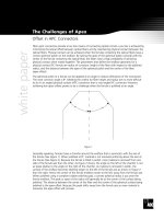
• Bend radius: At turns in fiber runs, maintain a 1.5-inch
bend radius. Tighter bends may cause micro-bending
of individual fibers that allow light to escape the signal
path, resulting in signal attenuation. More severe
bends can break fiber strands completely, resulting in
signal loss.
• Cable troughing: Used to route fiber optic cable,
troughing systems provide a protected pathway for
fiber to traverse spans between rooms and equipment
racks. Good troughing systems will keep fiber separate
from coax cable, protect it from out-of-tolerance
bends and promote neat, easily accessible runs.
• Vertical cable protection: Allowing fiber to hang
unprotected from the back of equipment can be a
recipe for disaster. Exposed cables are easy to snag
accidentally with a hand or foot, which can result in
damage to the connector or fiber itself. Additionally,
over time the weight of hanging fiber can cause
bends outside the acceptable limit and consequential
damage to the fiber. Proper vertical cable
management in panels or equipment bays provides
adequate support, cable protection and a transition
from the vertical run to the back of the equipment
that does not damage the fiber.
• Cable pile-up: In horizontal fiber runs, it is
unacceptable to allow a pile of fiber cable to exceed
two inches. Beyond that point, the weight of the
bundle will surpass the crush tolerance limit of the
fiber at the bottom of the stack, resulting in
microscopic damage and signal attenuation.
• Cable segregation: Keep fiber runs separate from legacy
coax cable. Coax is relatively heavy and can crush fiber
cables. Additionally, segregating coax from fiber ensures
that technicians repairing coax do not accidentally
damage the fiber cable while working on the copper.
• Labeling: Develop good labeling practices. Know where
fibers originate and terminate. Doing so will reduce
maintenance time and the likelihood that a maintenance
tech will make hasty decisions on fiber routing that can
lead to a rat’s nest of cable and patch cords.
• Density: When selecting products for a fiber network,
remember future maintenance. The more densely
connectors are packed onto a panel, the more difficult
it will be for even the most dexterous technicians to
maintain. Remember, inevitably cables will be moved,
so the ability to trace and re-route them is critical to
working efficiently.
• Future proofing: When planning rack configurations
with a given number of terminations to accommodate
a relatively low number of fibers for today’s
requirements, don’t forget the future. A fiber path
that easily supports 12 fibers today may be inadequate
to support the 200 fibers needed in a few years.
Planning up front for the future can save the expense
of ripping out outgrown capacity down the road.
Proper cable management is extremely important to the
successful conversion of broadcasters from coax to fiber.
The fact that a single fiber may transmit mission-critical
signals, such as revenue-generating commercials and
programming, underlies the importance of taking the
steps necessary to manage fiber’s installation and use.
Point at Which
Light is Lost
From Fiber
Optical Fiber
Light Pulse
Macrobend
Area
in Which
Light is
Lost From
Fiber
Optical Fiber
Light Pulse
Radius of
Curvature
1) Key Fiber Cable Management Concepts
Microbend
Integrating fiber into a broadcast facility requires a logical
means of connecting various devices throughout the
facility for production, playback and post-production
tasks, not unlike what has been done for years with coax
cable, patch panels and routing switchers.
On the most basic level, there are three approaches to
network architecture:
• Direct connect: This approach is straightforward, but
exceedingly limited. The output of one device is
connected to the input of another. While the least
costly of the three, it is inflexible and requires
manually moving cables at potentially far-flung source
and destination points in order for them to be
reconfigured. This approach has limited usefulness in
broadcast applications.
• Interconnect: This architecture relies on a passive
patch panel to act as an intermediate point where
fiber from devices like tape machines and still stores
can be connected. While eliminating the need to hike
to remote equipment locations to remove a cable from
one device so that it can be reconnected to another,
the interconnect architecture isn’t without its
downside. The lack of circuit access makes remote
monitoring, testing and patching impossible.
• Cross-connect: With a centralized cross-connect
patching system, achieving the dual requirements of
lower costs and highly reliable service is possible. In
this simplified architecture, all network elements have
permanent equipment cable connections that are
terminated once and never handled again.
Technicians isolate elements, connect new elements,
route around problems, and perform maintenance and
other functions using semi-permanent patch cord
connections on the front of a cross-connect system. Here
are a few key advantages provided by a well-designed
cross-connect system:
• Lower operating costs: Compared to the other
approaches, cross-connect greatly reduces the time it
takes for adding cards, moving circuits, upgrading
software, and performing maintenance. Because all
changes are made at one convenient location,
technicians are able to quickly and accurately perform
their work.
• Improved reliability and availability: Permanent
connections protect equipment cables from daily
activity that can damage them. Moves, adds, and
changes are effected on the patching field instead of
on the backplanes of sensitive routing and switching
equipment, enabling changes in the network without
disrupting service. With the ability to isolate network
segments for troubleshooting and reroute circuits
through simple patching, technicians can perform
maintenance without service downtime during regular
hours instead of during night or weekend shifts.
These three approaches to fiber network design and
signal routing offer an ascending ladder of flexibility,
convenience and control. On the bottom rung is direct
connection between devices. For broadcast applications,
this configuration is not recommended. The interconnect
architecture is most practical approach when there is
limited rerouting of inputs and outputs and circuit access
is not important. The cross-connect architecture stands
at the top of the ladder, providing the flexibility and
reliability broadcasters need in signal routing.
Top Ten Things to Know
Page 4
2) Making Connections: Direct, Interconnect and Cross-Connect Approaches
Direct Connect
Cross-Connect
Interconnect
Top Ten Things to Know
Page 5
As the broadcast industry makes its transition from
analog service to Digital TV, broadcasters are being asked
to address issues they hadn’t considered even a few years
ago. What’s the right mix of multicast DTV channels?
Should HD programming be originated locally or should
SD be upconverted? What sort of DTV transmission
scheme is appropriate? Will distributed transmission solve
coverage problems and if so, how will STLs to multiple
digital transmitter sites best be accomplished?
With each new question comes a growing recognition
that the existing plant must be upgraded or in extreme
cases replaced entirely to answer the demands of
broadcasting in a digital world.
As broadcast engineers grapple with these questions, the
need has never been greater to route more signals
between more devices with greater bandwidth. Whether
it’s HD studio cameras, multiple STL links or distribution
of wide band signals throughout the station, fiber optic
cable offers an affordable alternative to copper coax
cable. Additionally, its greater bandwidth capacity future-
proofs installations as increased bandwidth demands are
more easily accommodated than with copper.
Fiber optic cable comes in two varieties: singlemode and
multimode. Both have applications for broadcasters.
Singlemode fiber optic cables transmit a single ray of
light used to carry modulated signals. It is normally used
in applications requiring the transmission of signals over
a long distance. In the broadcast industry, singlemode
fiber is well-suited for applications such as studio-to-
transmitter links, camera control units and runs from a
studio to satellite earth stations or to cable headends, or
between separate facilities on a broadcast campus.
Multimode fiber optic cable carries multiple light rays
with different reflection angles within the fiber core.
With a fiber core that’s thicker than singlemode fiber,
multimode cable is better suited for short runs, such as
those between equipment and panels in broadcast
facilities. Multimode may be used to feed routers,
servers, editing stations and video servers.
Replacing copper with fiber is no longer economically
impractical at broadcast facilities. Once regarded as
expensive, the proliferation of fiber for business LANs
and WANs and its use in telecommunications
networks has brought an economy of scale to bear for
fiber cable, connectors and components that can
benefit broadcasters.
A recent study comparing the costs of first-time
installations of fiber with copper (CAT5, CAT5e and
CAT6) found that an “all-fiber solution offered a lower
total initial cost than the UTP-fiber network” for 12
scenarios that were studied.
According to the study, conducted by Pearson
Technologies Inc. and the Fiber Optics LAN Section of the
Telecommunications Industry Association, “In many cases
deploying multimode fiber cable throughout the network
is significantly less expensive than installing new grades
of UTP copper cable.”
These new marketplace realities could not have been
timed any better for broadcasters grappling with how to
modernize their facilities for the demands of DTV in a
cost-effective way.
Fiber offers other benefits broadcasters will find
attractive. On a physical level, it requires far less space
than coax. Fiber connectors are also physically smaller
than their coax counterparts.
Additionally, fiber optic cable offers broadcasters a level of
security that exceeds copper or microwave transmission
because it is difficult to tap without breaking.
3) Singlemode versus Multimode Fiber
Fiber Applications in a
Broadcast Family
Attaching a connector to a fiber optic cable will cause
some of the light traversing that fiber to be lost.
Regardless of whether the connector was installed in the
factory or the field, its presence will be responsible for
some light being reflected back towards its source, the
laser. Commonly known as return loss (RL), these
reflections can damage the laser and degrade the
performance of the signal. The degree of signal
degradation caused by RL depends on the specs of the
laser; some lasers are more sensitive to RL than others.
Different types of applications tolerate different degrees
of RL too. The experience of the cable television
industry has shown video equipment only tolerates a
minimal level of optical return loss. Similarly, high
bandwidth broadcast applications (such as
uncompressed HD) and long haul links between studios
and transmitter sites require minimal RL.
The amount of optical return loss generated is related
to the type of polish that is used on the connector.
The “angled physical contact” (APC) connector is best
for high bandwidth applications and long haul links
since it offers the lowest return loss characteristics of
connectors currently available. In an APC connector,
the endface of a termination is polished precisely at an
8-degree angle to the fiber cladding so that most RL is
reflected into the cladding where it cannot interfere
with the transmitted signal or damage the laser source.
As a result, APC connectors offer a superior RL
performance of -65 dB. For nearly every application, APC
connectors offer the optical return loss performance that
broadcasters require to maintain optimum signal integrity.
However, it is extremely difficult to field terminate an
angled physical contact connector at 8 degrees with any
consistent level of success. Therefore, if an APC
connector is damaged in the field it should be replaced
with a factory terminated APC connector.
The “ultra physical contact” (UPC) connector—while not
offering the superior optical return loss performance of
an APC connector—has RL characteristics that are
acceptable for intraplant serial digital video or data
transmissions. When using UPC connectors, make sure
your laser’s specs can handle the return loss your UPC
connectors will generate.
Offering –57 dB RL, ultra physical contact connectors rely
on machine polishing to deliver their low optical return
loss characteristics. Ultra physical contact polishing refers
to the radius of the endface polishing administered to
the ferrule, the precision tube used to hold a fiber in
place for alignment. The rounded finish created during
the polishing process allows fibers to touch on a high
point near the fiber core where light travels. Unlike APC
connectors, UPC connectors can, with the proper tools
and training, be repaired in the field.
Top Ten Things to Know
Fiber Casing
Fiber Core 8° Angled Endface
Ø
2
Ø
1
Ø
3
Ø
3
> Critical angle defined by Snells Law
Ø
1
=Ø
2
Light is reflected into cladding along Ø
3
n
1
n
2
Fiber Casing
Fiber Core
polishing creates
a rounded finish
4) Ultra Physical Contact Connectors and Angled Physical Contact Connectors
Angled Physical Contact (APC)
Ultra Physical Contact (UPC)
Top Ten Things to Know
Several fiber connector styles are popular today, including
SC, ST
®
, FC, Duplex SC, LC, LX.5
®
, MTRJ, and MTP, but
some are more appropriate for use at broadcast facilities
than others. Of the traditional singlemode and
multimode connectors, FC, SC, LC, and LX.5 are the only
ones that can be “angled physical contact” (APC)
polished. FC, SC, LC, LX.5 and ST can be polished using
the “ultra physical contact” (UPC) method.
Newer, small-form-factor connectors, such as the LC
and LX.5, also are appropriate for broadcast
applications requiring density on patch panels.
As discussed previously, in an APC polished connector
the endface of a termination is factory-cut precisely at
an 8-degree angle to the fiber cladding. This design
reflects most of the return loss (RL) to the cladding, not
all back to the source. As a result, APC is ideal for high-
bandwidth and long distance broadcast applications. In
an ultra physical contact connector, machine polishing
creates a rounded finish to the fibers being connected
so that they touch on their high points. While the RL
specs for UPC are not as good as APC, they are fine for
serial digital video and intraplant optical transmissions.
The types of fiber connectors appropriate for broadcast
applications include:
• SC – “Sam Charlie” or “Snap Click”: The most
popular of all connectors, the SC style offers
excellent loss characteristics and comes in a
standard footprint. It is easy to snap in and remove.
The SC is pull-proof and is available in UPC and
APC styles.
• FC – “Frank Charlie”: One of the most popular
connector styles, the FC offers excellent loss
characteristics and comes in a standard footprint.
The FC inserts by twisting a threaded connection
with key alignment. It is pull-proof, being difficult to
remove. Made from metal components it is available
in UPC and APC styles.
•ST
®
– “Sam Tom”: Very similar in appearance to a
BNC connector, the ST is a screw-on type connector.
It does not offer the pull-proof resiliency of SC and
FC connectors. ST connectors, which are made of
metal components, are only available with UPC
polishing. In recent years, the popularity of ST
connectors has waned as the use of SC and FC
connectors has grown.
• Duplex SC: Offers the same features as the SC style
but supports two-way communication.
• LX.5
®
: Exactly half the size of an SC connector, the
LX.5 offers twice the density of its larger
counterpart. Key to the LX.5 is its use of safety
shutters on both the connector and the adapter
body to provide protection from dust, dirt and
damage from ferrule endface handling. Available in
UPC and APC.
• LC: The LC comes in a small-form-factor that
competes with the LX.5. The LC features are similar
to SC, but its size allows double the density.
Available in UPC and APC.
When designing a fiber network for routing signals
through a broadcast facility, standardizing on a single
connector type will make network repairs and
technician training faster and less expensive. However,
despite efforts to standardize on a single connector
style, it may be necessary to use a hybrid cable to move
the set standard.
Adopting the LC or LX.5 style connector makes sense in
a broadcast facility because of the sheer number of
sources and destinations common at stations and the use
of multicore fiber to route signals between them. The
smaller size of the LC and the LX.5 connector means
more individual strands of multicore fiber can be broken
out, connectorized and accommodated on a patch panel.
As long as the panel is designed ergonomically so that
technicians and engineers can actually grasp a patch cord
connector connected to a densely-packed panel, this
application of LC and LX.5 connectors is sound. If the
panel is packed too densely, there is always the option of
breaking out individual fibers of a multicore run to larger,
easier-to-grasp SC connectors.
Ease of use and protection against fibers being
accidentally pulled is more important in broadcast
facilities, as fiber panels are typically installed in high-
traffic areas.
6) Connector Styles
Broadcast engineers who cut their technical teeth
attaching connectors to coax cable might be surprised
to learn that when working with fiber, relying on
factory-terminated cables offers several advantages over
field termination, including performance and savings in
labor, material costs and installation time.
Unlike field-terminated fiber, preconnectorized cable
assemblies are guaranteed to work out of the box to
the highest performance specification. Under the best
circumstances, field-terminated cables offer 0.5 to 0.25
dB signal loss, while factory-terminated fiber delivers
typical loss of less than 0.2 dB. Factory termination will
provide consistent loss values, making network
planning more accurate.
Engineers who have worked hard over the past several
years to implement video production workflow
solutions that improve productivity have personal
knowledge of the ongoing efforts at stations to work as
efficiently as possible and to use labor wisely. Against
this backdrop, using factory-terminated fiber in stations
makes a lot of sense.
The labor savings associated with using factory-
terminated cables in most instances make it a more
economical solution than field termination of fiber
cables. Not only do factory-terminated cables eliminate
the labor costs associated with installing connectors in
the field, they also do away with the need to spend
money on re-doing work that has failed as well as the
cost of additional connectors. Factory-terminated cable
comes from the manufacturer where it was prepared
under the supervision of fiber optic experts in an
environmentally controlled setting with quality
inspection and testing. Connectors are attached to
individual strands of fiber in an automated factory
process that is not as subject to human error. Once
attached to the fiber cable, the connections are tested
to ensure quality and performance.
When fiber is terminated in the field, bulk cable arrives
at the broadcast facility on optical cable reels with
packages of connectors. That cable must be pulled
between points and attached to patch panels at both
ends of each run. Before it can be attached to the
panel, technicians must attach connectors to each
strand of fiber. Those field-terminated connectors,
which get plugged into the back of patch panels, can
fail or perform below acceptable signal loss tolerances.
Relying on factory-terminated cable requires some
forethought and planning. Knowing where panels must
be located and the length of runs from the panel to
various pieces of equipment is necessary, but it’s also
important to know how best to bring panel, fiber and
equipment together. One approach is using multifiber
cable with factory-terminated connectors attached to
one end for the equipment side of the run. At the
patch panel, a factory-connectorized pigtail plugs into
the back of the panel leaving a factory-prepared stub
end ready for splicing. Station technicians then splice
individual strands of the multifiber cable to single
strands of fiber making up the pigtail.
The other approach is similar. Here factory-connectorized
pigtails are used on both the equipment and the patch
panel ends of the run. Broadcast technicians then splice
individual strands of fiber (see the next section on
splicing to learn more) in the multifiber cable between
both ends to individual fibers in both pigtails.
For broadcast engineers who have grown up in the
business cutting coax to length and attaching
connectors, these approaches might seem a little foreign.
However, the clear advantages of lower labor costs,
higher performance and the elimination of wasted
material and time offered by using factory-terminated
fiber optic cable make a little re-orientation in
engineering mindset and practice more than worthwhile.
Top Ten Things to Know
Page 8
6) Field versus Factory Connector Termination
Top Ten Things to Know
Page 9
Common practice among broadcast engineers calls for
cutting coax to the desired length and attaching
connectors in the field. Doing so with coax is fast, easy,
and results in precise control over cable length.
However, that isn’t always the best solution for fiber,
especially when cable runs are longer than 25 meters,
singlemode fiber is being used, or a degree of
permanency is required.
For those situations, splicing individual fibers as shown
in figure 1 offers an attractive alternative. Among the
benefits of splicing fiber are lower signal loss, more
predictable results and the faster speed at which it can
be done by a trained technician.
Fusion splicing of fiber in the field offers substantially
greater efficiencies in time and performance than
attaching connectors. Fusion splicing fibers is done by the
following process:
• Outer jacket removed from multicore cables and
broken out to individual 900 micron cables and
strength member or yarn trimmed
• Individual fibers are stripped to 250 micron bare fiber
• Fiber cleaved, resulting in a flush end
• Fiber prepared for splicing by cleaning the ends and
putting a shrink tube over one end
• Both cables put into the alignment device on the
splicing equipment, which will align the fiber ends
• Laser fusion procedure initiated on the equipment
• Technician removes the fusion splice and visually
inspects the junction with a high powered microscope
(typically part of the splicing equipment kit)
• Fusion splice secured into the splice holder on the
fiber panel splice tray
Trained technicians can splice two strands of fiber
together in as little as 5 minutes, which compares to 15
minutes per field-terminated connector. The efficiency of
splicing becomes even more pronounced when
comparing splicing a 24 fiber cable to field terminating it
– 2 hours vs. 12 hours.
The difficulty of adding connectors in the field also
means that the yield of acceptable connections will be
directly related to the skill level and experience of the
technician. Unlike fusion splicing, there is no automatic
labor savings associated with field terminating connectors
and testing connections. Anecdotal experience indicates
that as many as 50 percent of field-installed connectors
fail when done by green technicians, resulting in time-
consuming, costly do-overs.
In terms of performance, field-terminated singlemode
connectors can leave engineers wanting. Under the best
circumstances, they offer 0.25 dB signal loss, while loss
from fusion splicing typically is 0.01 dB.
Splicing is most appropriate for long runs of fiber
between buildings or separate floors of the same
building and is best-suited for applications where
connections are intended to be permanent. It provides
the best solution for connecting points separated by an
unknown distance.
Conversely, preterminated connectors or field
termination, as shown in figure 2, is a better solution for
short runs of multimode fiber. Field-terminated
connectors make the most sense for multimode fiber
between two points separated by a known distance.
7) Splicing vs. Field Connectorization
Figure 1: Splicing at both
panels is most appropriate
for long runs of
singlemode fiber where
distances are unknown
and connections are
intended to be permanent.
Figure 2: Field terminated connectors
are a good solution for short runs of
multimode fiber between points
seperated by a known distance.
Unmanaged patch cord slack is a silent threat to mission-
critical operations at broadcast facilities using fiber optic
cable to route signals around the facility. A misplaced
foot or wandering hand can accidentally snag exposed
loops of fiber patch cord and pull it with enough force to
damage optical fibers and harm connectors. More
importantly, untended patch cord slack that gets yanked
might be carrying a commercial to air, requiring
expensive make-goods, or interrupt an edit session for an
important client. In either case, the resulting harm could
be far greater than cost of a little prevention.
Broadcast engineers planning an upgrade or system
change-over to fiber optic cable should include storage
of slack patch cords in their plans from the outset.
Besides the ability of proper slack management to tidy
up the look of a facility, it also elevates the confidence
level of station engineers as they work in equipment
racks free from the fear that a false move might
accidentally do harm.
Another important benefit of having a dedicated slack
storage system for patch cords is the ability to specify a
single patch cord length for the entire plant. Proper slack
storage means that a 5-meter patch cord can be used for
a long or short patch without fear that dangling excess
fiber will be damaged.
Stations entwined in a rat’s nest of patch cords can
improve the appearance of their rack areas and make
patching much simpler with proper slack storage.
Systems that store patch cord slack properly maintain a
minimum bend radius of 1.5 inches to protect against
damage to fiber. They also provide easy access for
convenience when it’s necessary to reconfigure a patch.
From integral storage compartments in stand-alone
termination cabinets to 19-inch 1RU fiber management
trays, slack storage systems can take many shapes. But
the common thread among all of these systems is that
extra patch cord lengths are neatly stored, protected
from damage and aren’t exposed to accidents that can
negatively impact the ability of a facility to earn revenue.
Top Ten Things to Know
Page 10
8) Slack Storage: Protecting and Managing Fiber Cables
Bulk/Storage Drawer Fiber Storage Tray Panel
Interbay Management Panel
Top Ten Things to Know
Page 11
While the explicit promise of fiber optic cable is that it’s
an affordable, wide-band alternative to coax,
impervious to RF interference, its implicit promise is that
fiber is smaller, neater and easier to manage. Barely the
width of a human hair, a fiber core—even when
surrounded by layers of cladding, coating, strength
fibers and a cable jacket—holds out the hope that the
untraceable spaghetti-like mess of coax cable at some
television stations and networks can one day fade into
a distant memory.
In its place, equipment racks filled with neatly arranged,
tightly packet fiber connectors promise to bring back a
little sanity and manageability to cable runs and
equipment racks. However, high density fiber patch
panels, small-form-factor connectors and multifiber
ribbon connectors might actually be too much of a
good thing because there’s more to consider than
simply how much rack space will be used.
Broadcast engineers walk a fine line trying to balance
their desire to maximize rack space and eliminate the
coax clutter, with the practicality of maintaining densely
packed connectors and cables.
What price must be paid to maximize rack space? Will
densely packed connector panels make it more time-
consuming to perform maintenance because it’s harder
to grasp a connector or cable without disturbing any
others? Does the fact that they are crammed together
make these connectors more likely to be damaged?
The truth is anyone can put more connectors on a
bulkhead plate. But does it have the built-in cable
management features to accommodate that density?
There’s a tendency when using tightly packed connector
panels to force fiber into sharp bends that could
damage the fiber core and attenuate the signal. More
cable also means an increased tendency to overlook
recommended cable pile-up tolerance and adequate
slack storage practices. Additionally, densely-packed
connectors can make it impossible for a technician to
access a single fiber as opposed to all of them at once.
Ironically, when it comes time to expand the
installation, density may prove to be the ultimate
impediment to growth. It is possible to have half-full
racks, that lack cable management features, so tightly
packed with cables and connectors that new fiber
panels cannot be added. In that case, the only
alternative is to rip out the existing rack and start from
scratch—a real waste of the initial outlay. The best way
to avoid this potential problems is to invest in fiber
infrastructure that has built-in cable management
features and allows you to scale efficiently.
9) Fiber Density
ADC Telecommunications, Inc., P.O. Box 1101, Minneapolis, Minnesota USA 55440-1101
Specifications published here are current as of the date of publication of this document. Because we are continuously
improving our products, ADC reserves the right to change specifications without prior notice. At any time, you
may verify product specifications by contacting our headquarters office in Minneapolis. ADC Telecommunications,
Inc. views its patent portfolio as an important corporate asset and vigorously enforces its patents. Products or
features contained herein may be covered by one or more U.S. or foreign patents. An Equal Opportunity Employer
1305075 10/04 Original © 2004 ADC Telecommunications, Inc. All Rights Reserved
Web Site: www.adc.com
From North America, Call Toll Free: 1-800-366-3891 • Outside of North America: +1-952-938-8080
Fax: +1-952-917-3237 • For a listing of ADC’s global sales office locations, please refer to our web site.
WHITE PAPER
10) Planning for Future Growth
Broadcast engineers who plan to add fiber to an
existing coax plant or to build a fiber-based facility
from scratch should not ignore the demands for
system growth that they inevitably will face.
What today seems like abundant capacity in a
network with 24 or even 12 fibers will seem
paltry, over-taxed and inadequate in a few years.
One only needs to remember the “huge” 40MB
hard drives in personal computers that “never”
would be filled to understand how demand
quickly catches up with and surpasses capacity.
When building a fiber network, it is essential that
future growth is considered and good cable
management practices employed. Practices such
as following a 1.5-inch bend radius policy,
guarding against excessive cable pile-up,
troughing horizontal runs, implementing vertical
cable protection and providing for expanding
slack storage needs will minimize the possibility
that an initial fiber cable installation will be
damaged and allow the fiber network to grow
more easily and quickly.
Plans for future growth should take today’s
typical broadcast network topology into account
as well as make provisions for centralized
operations tomorrow. As it’s envisioned and
being implemented, three separate approaches
to centralization exist:
• Total centralcasting where all commercials and
programming except local news is sent to local
stations from a central network operations
center via wide area network. All operations,
including things as diverse as traffic and
master control, are centralized at the network
operations center.
• Centralized content aggregation where all
programming except local news is collected,
quality control checked and sent to local
stations across a WAN, but traffic, master
control and billing are done locally.
• Centralized personnel model where personnel
at local stations ingest content, prepare it for
air and perform quality control checks and the
network operations center controls station
automation and master control from the
network hub over a WAN.
These radical departures from business as usual
at facilities mean that the wise engineer
designing a fiber network for a broadcast facility
will be mindful of the prospect of centralized
operations in the future and the demands it will
place on existing fiber and the need to grow.
Conclusion
As the broadcast industry evolves fiber is more
frequently being deployed as the preferred
medium for high bandwidth applications like
HDTV. Proper cable management is critically
important as fiber upgrades are made. The
successful conversion from coax to fiber starts
with advance planning that addresses all key
issues including proper cable management. The
fact that a single fiber may transmit mission-
critical signals, such as revenue-generating
commercials and programming, underscores the
importance of taking the steps necessary to
manage fiber’s installation and use.