Tài liệu cisco migration_Network Virtualization—Network Admission pdf
Bạn đang xem bản rút gọn của tài liệu. Xem và tải ngay bản đầy đủ của tài liệu tại đây (308.06 KB, 14 trang )
Americas Headquarters:
© 2007 Cisco Systems, Inc. All rights reserved.
Cisco Systems, Inc., 170 West Tasman Drive, San Jose, CA 95134-1706 USA
Network Virtualization—Network Admission
Control Deployment Guide
This document provides guidance for enterprises that want to deploy the Cisco Network Admission
Control (NAC) Appliance for their campus users. Two solutions for Network Admission Control are
proposed and analyzed in this document, at both the architectural and functional levels. For related
information, see the following documents:
• Network Virtualization—Access Control Design Guide (OL-13634-01)
• Network Virtualization—Guest and Partner Access Deployment Guide (OL-13635-01)
• Network Virtualization—Services Edge Design Guide (OL-13637-01)
• Network Virtualization—Path Isolation Design Guide (OL-13638-01)
Contents
Introduction 1
Business Problem 2
End-to-End Network Virtualization Solution 3
End-to-End Overview 3
User Authentication and Access 4
Path Isolation 4
Services Edge 6
Network Virtualization Deployment Scenarios 6
Network Admission Control—Option A 6
Access Control 7
Path Isolation 8
Services Edge 10
Network Admission Control—Option B 11
Access Control 11
2
Network Virtualization—Network Admission Control Deployment Guide
OL-13636-01
Introduction
Path Isolation 12
Services Edge 12
Introduction
This document provides network architects with a general understanding of how to leverage network
virtualization to make a centralized NAC Appliance deployment easier. This document allows the
network architect to select a design and reference the specific implementation details in the associated
design guides. The foundation technologies associated with enterprise network virtualization
architecture are divided into the following three functional areas:
• Access control
• Path isolation
• Services edge
Several technologies and techniques can be used to provide the functionality required in each area.
Rather than attempting to provide detailed information for every available technology option within the
scope of this document, a separate set of design guides provide more information on each of these
technologies:
• Network Virtualization 2.0—Access Control Design Guide
• Network Virtualization 2.0—Path Isolation Design Guide
• Network Virtualization 2.0—Services Edge Design Guide
This modularity provides the flexibility to combine various sections of these design guides to tailor the
solution implementation documentation to better serve customer requirements and architect choices.
Most enterprise networks do not perform user validation or security posture checking for systems before
allowing a device access to the network. Typically, any network device can be connected to any open
wired network port, which exposes the enterprise to insecure devices and potentially infected machines.
Devices that do not comply with the enterprise network access policy can greatly affect the availability
of network resources to the enterprise by spreading worms and viruses and placing vulnerable machines
that can be targeted by attackers inside the corporate environment.
IT departments are tasked with providing reliable secure network services for customers, partners, and
guests, and need a way to check devices for compliance with corporate security policy. Cisco NAC
provides a mechanism to authenticate a user before being allowed access to the corporate network, and
to verify that the device with which they are connecting meets the corporate security policy (anti-virus,
up-to-date service packs, and patches are applied). If a device is out-of-policy, NAC provides a
mechanism to automate remediation of the system without a call to technical support. Enterprise
networks today must accommodate partner and guest access in addition to the traditional corporate
employee access. NAC supports this functionality with different access policies for different user types.
A NAC policy may grant a guest user Internet access only, a partner may have access to the Internet plus
a limited set of internal corporate systems, and internal employees can have full access.
NAC deployments currently consist of two key pieces: a NAC Appliance Manager that is centrally
deployed, and several NAC Appliance Servers that are distributed throughout the campus. In many
environments, a distributed deployment can be cost-prohibitive because of the large number of NAC
Appliance Servers that must be deployed. Virtualization enables an enterprise to centralize all the NAC
Appliance Servers into the data center, achieving better economies of scale, and provides an isolated
network for remediation. A virtualized deployment can reduce the number of devices needed to cover a
campus, providing both capital and operational cost savings.
3
Network Virtualization—Network Admission Control Deployment Guide
OL-13636-01
End-to-End Network Virtualization Solution
By implementing a NAC solution, enterprises can control network access, prevent un-patched systems
from gaining access to the corporate network, quarantine systems that do not meet policy, and remediate
with little or no help from IT.
The main technical requirements for a virtualized NAC solution are as follows:
• Isolation of the device from the internal enterprise until the user is authenticated and the access
policy is applied
• Isolated remediation on the virtualized network
• Automated remediation of out-of-compliance asset
• Support for both wired and wireless access
• Provisioning for multiple user types (employee, partner, guest)
• Authentication and authorization for user and device
• Minimize the number of managed devices
• Better utilization of user licenses
End-to-End Network Virtualization Solution
To provide virtualized NAC, a virtual network is created for authentication and quarantine. This virtual
network is logically overlaid onto the existing infrastructure, and allows connectivity only to
authentication and remediation resources. After the user is authenticated and the access device meets
policy, the NAC manager can place the device into the appropriate VLAN.
End-to-End Overview
The goal with this solution is threefold:
• Identify, authenticate, and associate the user to the access policy
• Isolate the user device from the production network while checking the device posture, and to
remediate if necessary
• Move the device into the appropriate network segment
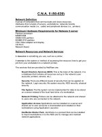
The solution framework is divided into three functional areas (see Figure 1), each of which maps to one
of these objectives:
• User authentication
• Path isolation
• Services edge
4
Network Virtualization—Network Admission Control Deployment Guide
OL-13636-01
End-to-End Network Virtualization Solution
Figure 1 Solution Framework—Three Functional Areas
The end-to-end solution involves an optimal combination of chosen technologies available in each
functional area.
Note The main goal of this deployment guide is to provide an end-to-end virtualized NAC solution. This
means that the technical elements comprising the path isolation and services edge functional areas are
shared and valid for both categories of users.
User Authentication and Access
When users connect to a NAC-enabled network, they are placed into the authentication and remediation
virtual network and challenged for authentication credentials. User authentication can happen via the
Cisco NAC client software, web-based authentication, a guest access button, or MAC white listing.
Authentication is used to associate a user with an access policy and to put the client in the proper VLAN.
Switch port state for users connecting to an Ethernet port include the following:
• Static port configuration—A port is statically assigned to a VLAN and not managed by NAC; the
port is in turn statically associated with a virtual network or segment. This may be done to
accommodate a specific type of network device but care must be taken to protect the physical port
153769
LWAPP
1. Identify & authenticate
client (user, device, app)
attempting to gain
network access
2. Isolate into a Segment
3. Grant _controlled_access
or prevent access
1. Map client VLAN to
transport technology
2. Transport client traffic
through isolated path
3. Terminate isolated
path @ destination edge
1. Map isolated path to
destination VLAN
2. Apply policy at VLAN
entry point
3. Isolate Application
environments
IP
GRE
VRFs
MPLS
Functions Access Control Path Isolation Services Edge
Branch - Campus WAN – MAN - Campus Data Center - Campus
5
Network Virtualization—Network Admission Control Deployment Guide
OL-13636-01
End-to-End Network Virtualization Solution
because an attacker could disconnect the device and gain network access via this port. Cisco
recommends that these ports be placed into a VLAN with application-specific filters to restrict the
ability of an attacker to use this port to gain general network access.
• Authentication VLAN—This is the VLAN into which all users are placed when connecting to the
network. The authentication VLAN is mapped to the authentication virtual network isolating all
traffic from the corporate network. If any remediation is necessary, the user is quarantined in this
VLAN until the system passes all checks and then the device is moved to the access VLAN.
• Access VLAN—The access VLAN into which the user is placed can vary by user type. One access
VLAN can be used for all users once authenticated, or different VLANs can be used for different
user types. These user VLANs can be further isolated with distributed access control lists (ACLs)
or by being mapped to virtual networks.
• MAC White Listing—This feature can be enabled on the NAC Manager to allow the switch to use
the MAC address as the client identity. In this case, NAC Manager has a database of client MAC
addresses that are allowed network access. This is useful for devices such as printers and other
network-enabled devices that are unmanned.
Path Isolation
Before a device has been allowed access to the corporate network, it must be authenticated and
potentially remediated. While the device is being checked, it needs to be isolated from the corporate
network. To achieve this, you can keep traffic logically isolated by using separate Layer 2 domains for
authentication and access. To preserve end-to-end separation, these Layer 2 domains must be extended
across the entire network. Extending Layer 2 domains end-to-end negates all the scalability and
modularity benefits achieved by a hierarchical network design. IP routing is at the heart of the
hierarchical design because of its ability to limit the size of broadcast domains and to lessen the impact
of failures and changes by providing a modular structure that can prevent problems from propagating
and affecting the entire network. A mechanism to provide network virtualization while preserving the
scalability and modularity of the routed network is necessary.
When the Layer 2 domains at the edge are connected to the routed core of the hierarchical network, the
logical isolation achieved at the edge by the Layer 2 domains is lost. Virtualized NAC requires that the
initial authentication and remediation traffic to be routed to the NAC Appliance Servers located in the
data center. A mechanism to give continuity to those segments over the routed core is needed.
The following alternatives are available to maintain this logical traffic separation in the Layer 3 domain
of the enterprise network:
• Distributed ACLs and Policy-Based Routing (PBR)—ACLs can be configured at the frontier points
between the edge Layer 2 domains and the routed core. These ACLs should ensure that hosts in the
authentication VLAN can reach only the NAC Appliance Servers and any systems needed for
remediation. PBR is then used to forward all authentication VLAN traffic to the NAC Appliance
Servers in the data center. PBR must be configured hop by hop, it complicates device configurations,
and can make troubleshooting difficult. Because of this, distributed ACLs and PBR is not
recommended for campus NAC deployments.
• Overlay of Generic Routing Encapsulation (GRE) tunnels interconnecting VRFs—Another
mechanism to provide continuity over the routed network to the logical separation provided by
VLANs at the edge is to use IP tunnel overlays. A tunnel overlay (either in a full or partial mesh) is
created for the authentication network. In this design, the access VLANs are placed into the global
table. The tunnel overlay is mapped to the authentication VLAN at the first Layer 3 gateway
(typically the distribution layer but it can be the access layer if a routed access design is used). This
both isolates the authentication and remediation traffic and removes the need for PBR because all
traffic is routed up to the data center and handed off to the NAC appliances.
6
Network Virtualization—Network Admission Control Deployment Guide
OL-13636-01
End-to-End Network Virtualization Solution
By associating the VLAN interfaces and the tunnel interfaces in a group to a VPN Routing and
Forwarding (VRF) instance, VLANs can be mapped to the required tunnel overlay. VRFs are
considered as virtual routers (although they are not strictly that) to which different interfaces can be
assigned. Assigning VLAN interfaces and tunnel interfaces to these virtual routers, or VRFs,
effectively creates a virtual network that has its own links and routed hops. Thus, a virtual network
built this way consists of VLANs, VRFs, and GRE tunnels, all working together to form a separate
overlay topology. A routing protocol must run between the VRFs and over the tunnel mesh to
provide the necessary reachability information. The underlying infrastructure is designed according
to well-known hierarchical and high resiliency principles. Therefore, the tunnel overlay enjoys these
benefits. See “
Network Virtualization Deployment Scenarios , page 7” for a high-level deployment
model. More information is provided in the Network Virtualization—Path Isolation Design Guide.
• MPLS/BGP VPNs (RFC 2547)—This technique uses Multiprotocol Label Switching (MPLS) to
dynamically create a tunnel mesh similar to the tunnel overlay Cisco created for the GRE-based
solution. These dynamic tunnels are better known as label-switched paths (LSPs), which handle
traffic forwarding, while Border Gateway Protocol (BGP) is used to carry routing information
between the VRFs. The separation of the control plane and the data plane is the key to being able to
create the LSPs dynamically. This is the most scalable technique of all of the techniques described,
but it is also the most demanding in terms of platform capabilities.
Although all the techniques listed can be used, some are better suited for a campus NAC deployment
than others. Distributed ACLs and PBR can be very difficult to manage and troubleshoot in a large
environment, and is not recommended unless it is the only option that the infrastructure supports. VRF
and GRE is a good solution if the network has no other requirement for virtualization. This approach is
straightforward to configure, and management and troubleshooting can be done by anyone that has a
routing and switching background. Full campus MPLS VPN is the best choice if the enterprise requires
multiple virtual overlay networks; for instance, if NAC, guest, and partner networks are required.
Whichever technique is used, it can be overlaid onto the existing infrastructure. This means that the
network continues to function as usual, and only traffic that is steered into the created virtual network is
isolated or segmented. When adding support for NAC, the requirement for isolation is the authentication
and remediation traffic only. This is achieved by creating a virtual network for NAC authentication traffic
using one of the methods listed above. Regular traffic continues to be forwarded as normal without
having to create a dedicated segment for any other category of users. Isolating the initial connection of
a user without altering the existing network traffic flow is the main benefit to this type of deployment
for NAC.
Services Edge
Users attaching to the NAC authentication virtual network are isolated from the main corporate
environment. Several services are needed from this isolated environment to enable a user to login and do
any necessary remediation. Services such as DHCP/DNS, access to authentication services such as
AD/LDAP (proxied through the NAC Appliance Server but perhaps requiring direct access), access to
remediation servers, and Internet access for remediation need to be pinholed through so that normal user
login can happen. The services edge also provides access to services that are shared between the NAC
and corporate networks. To achieve this, the services edge provides logical connectivity and security
mechanisms over shared facilities, such as firewalls, load balancers, and even intrusion detection
systems. For the purposes of the NAC connectivity scenario, connectivity is limited to the sharing and
virtualization of firewalls to provide screening for traffic from the quarantined environment and for
Internet connectivity, DHCP and DNS services for users on the NAC virtual network, and access to
authentication services.
7
Network Virtualization—Network Admission Control Deployment Guide
OL-13636-01
Network Virtualization Deployment Scenarios
Network Virtualization Deployment Scenarios
This section covers the following network virtualization deployment scenarios:
• Network Admission Control—Option A
• Network Admission Control—Option B
Network Admission Control—Option A
This end-to-end proposition includes the following components (see Figure 2):
• Access control—NAC client authentication or web-based authentication
• Path isolation—GRE tunnel overlay and VRF
• Services edge—Application Control Engine (ACE), Firewall Services Module (FWSM), and NAC
Appliance
8
Network Virtualization—Network Admission Control Deployment Guide
OL-13636-01
Network Virtualization Deployment Scenarios
Figure 2 End-to-End Network Virtualization
Access Control
When a user connects to the network, they are placed into an authentication VLAN by the NAC
Appliance Manager. The authentication VLAN has very limited access to the rest of the network;
typically, from this VLAN a user can access services that are needed for user authentication and OS and
application updates. Users can authenticate in one of two ways: if attaching to the network with a
corporate PC, the user is authenticated with the NAC client; if the system attaching to the network is
uncontrolled, the user is prompted to authenticate after opening a web browser. The NAC client can
support single signon so the user does not see a secondary authentication after logging onto their PC.
The NAC web authentication can support both username/password or guest access. After the user is
authenticated and the PC has passed all policy checks, the system is moved from the authentication
WAN
Internet Edge
Building
Web-auth
Internet
WAN
Guest VRF
Branch
Data Center
153765
LWAPP
WLC
WLSM
LWAPP
GRE
Campus
Core
WLC
LWAPP
LWAPP
9
Network Virtualization—Network Admission Control Deployment Guide
OL-13636-01
Network Virtualization Deployment Scenarios
VLAN to an access VLAN based on the user profile. The access VLAN can be identified by name or
number. Using the VLAN name, an enterprise can for example create a VLAN “Guest” on all switches
in the network and not have to match VLAN numbers from each switch to a profile on the NAC Manager,
simplifying management and reducing configuration errors.
Path Isolation
The first stage of the path isolation solution is the creation of a VLAN to use for network authorization.
This is very straightforward and all you have to do is add a new VLAN for authentication, following the
same guidelines used for the deployment of other VLANs in the network access layer. In the campus,
there is a separate authentication VLAN for each access layer switch.
Alternatively, a routed access layer can be used in which the VLANs are created at the access layer and
do not impact the configuration of the distribution layer switches. Typically, it is best to stay with the
current design in this model.
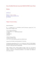
Figure 3 shows both the traditional and routed access campus deployments.
Figure 3 Traditional and Routed Access Campus Deployments
Next, the authentication VLAN is terminated into a Layer 3 VPN. In the associated design, the VLANs
are terminated at the distribution in the campus. This can be generalized to include the devices at the
border between the switched and routed portions of the network. In a routed access design, the
authentication VLAN is connected to the Layer 3 VPN in the access layer switches.
The authentication VLAN is kept separate from the rest of the network by mapping the VLAN to a VRF
at the first Layer 3 hop. The IP default gateway for all devices in the authentication VLAN is an address
in the VRF. By making the VLAN part of the VRF, the hosts in the authentication VLAN are removed
from the original global network and isolated from the rest of the network because the VRF is a separate
routing table. The result is similar to having connected the authentication VLAN to a separate physical
network that is not connected to the original global network. Traffic in the authentication VLAN does
not have a route or connection to the original network, and the original network does not know how to
get to the isolated authentication VLAN.
At this point, you have created a new VLAN for authentication and connected it to a Layer 3 VPN, a
virtual router instance, but communication is not enabled past this point in the network.
VLAN 240 Guest
172.16.2.0/24
VLAN 140 Data
10.1.140.0/24
VLAN 40 Data
10.1.40.0/24
149953
Campus
Core
Core
Layer
Layer 3
Layer 2
VLAN 220 Guest
172.16.1.0/24
VLAN 120 Data
10.1.120.0/24
VLAN 20 Data
10.1.20.0/24
VLAN 240 Guest
172.16.2.0/24
VLAN 140 Data
10.1.140.0/24
VLAN 40 Data
10.1.40.0/24
Campus
Core
Layer 3
Layer 3
VLAN 220 Guest
172.16.1.0/24
VLAN 120 Data
10.1.120.0/24
VLAN 20 Data
10.1.20.0/24
Distribution
Layer
Access
Layer
10
Network Virtualization—Network Admission Control Deployment Guide
OL-13636-01
Network Virtualization Deployment Scenarios
The next step is to connect the authentication VRF at the distribution switch back to the services edge
so that clients can communicate to the NAC Appliance servers and manager. A GRE tunnel from the
VRF in the distribution back to the VRF at the services edge switch can be used to accomplish this. The
overlay GRE tunnels create a logical network across the existing network. This overlay network is used
to carry traffic from clients while they are authenticated and their security posture is checked. Because
the VRFs are isolated and have only tunnel and VLAN interfaces associated with them, this network is
isolated from the rest of the infrastructure.
Figure 4 shows the original global network and the overlaid virtual network sharing the same
infrastructure.
Figure 4 VRF Overlay Network in the Campus
WAN
Internet Edge
Building
Web-auth
Internet
Guest VRF
Data Center
153766
LWAPP
WLC
WLSM
GRE
Campus
Core
11
Network Virtualization—Network Admission Control Deployment Guide
OL-13636-01
Network Virtualization Deployment Scenarios
This concept can be implemented with point-to-point GRE tunnels as well as multipoint GRE tunnels.
The details on how to do this are provided in the Network Virtualization—Path Isolation Design Guide.
For the specific NAC application, keep in mind that the requirement is for many-to-one connectivity, in
which many users are accessing a central NAC Appliance farm that provides authentication,
remediation, and network assignment.
GRE termination hubs are required for a termination point for the GRE tunnels from the distribution
layer in the campus. Typically, this termination point is in the services edge switches in the data center.
All GRE tunnels are terminated here and allow client traffic only to route to the services edge
environment for processing.
Figure 5 LAN and WAN GRE Tunnel Overlay (Private WAN)
Branch
LWAPP
LWAPP
Branch
WLC
LWAPP
LWAPP
Branch
WLC
LWAPP
LWAPP
Internet Edge
WAN
Building
Web-auth
Internet
WAN
Data Center
Hub-and-spoke
WAN
Hub-and-spoke
Campus
LWAPP
WLC
WLSM
LWAPP
GRE
153767
Campus
Core
12
Network Virtualization—Network Admission Control Deployment Guide
OL-13636-01
Network Virtualization Deployment Scenarios
Services Edge
In the services edge functional area, users access the following services:
• ACE modules
• DNS servers
• FWSM
• Internet
• NAC Appliance Servers and Manager
• Remediation servers
At the services edge, the clients are connected to the NAC Appliance servers. The appliances are fronted
by the ACE module that is used to load balance the inbound connections across a bank of NAC
appliances. The appliances authenticate the users and check the devices against the enterprise policy. For
this to be possible, the NAC Appliance must have access to backend authentication servers, typically AD
or LDAP, and the clients need to be able to access basic services such as HTTP, HTTPS, and DNS, as
well as any protocol that a corporate remediation or patching system might use.
If the clients successfully authenticate and pass the policy checks, they can be placed into a VLAN. The
client VLAN can be selected by name or number, but the best deployment method is to use VLAN
names. This allows the user to be placed into the same VLAN regardless of the access layer switch to
which they connect. For example, all the corporate access VLANs can be named “Employee” on the
access layer switches regardless of what the VLAN numbers are today. This way the configuration on
the NAC Appliance is greatly simplified (all corporate users can be sent to VLAN “Employee”
regardless of where they connect.)
If the clients lack authentication credentials but are guest users, a guest option can be displayed to the
user from the web login page. A guest user is not typically checked against any policy because they are
uncontrolled systems. Guests can be placed in a separate guest-only VRF or into a VLAN with limited
network access via ACLs. Common services used for guest and employee access can be shared. In many
cases, the same DNS, DHCP, and Internet systems are shared between the two user groups so that system
duplication is not necessary.
If the clients authenticate successfully but do not pass the policy check, they are placed into a quarantine
state. They stay in the authentication virtual network to isolate them from the corporate network. They
are given just enough access to remediate their system so that they are compliant (access to AV server,
SMS/SUS, windowsupdate.microsoft.com, and so on), and then placed into the appropriate VLAN after
they pass the checks.
Network Admission Control—Option B
This end-to-end solution involves the following:
• Access control—NAC client authentication or web-based authentication
• Path isolation—MPLS
• Services edge—ACE and NAC Appliance Server
13
Network Virtualization—Network Admission Control Deployment Guide
OL-13636-01
Network Virtualization Deployment Scenarios
Access Control
Access control for Option B is handled in the same way as for Option A. An additional VLAN is added
to each access layer, typically following the design in place for existing VLANs. This VLAN is named
“Auth-VLAN” and is the VLAN into which new users are placed when they connect to the network.
When authenticated and checked for policy compliance, the user is placed into the proper VLAN by the
NAC Appliance. The client VLAN can be mapped to any MPLS virtual network.
Path Isolation
Deploying with enterprise MPLS VPN is similar to the setup in Option A. The VRF with GRE tunnels
are replaced with the MPLS virtual networks. In an existing MPLS VPN design, an additional virtual
network is added to the existing networks and used for client authentication and remediation as they
joined the network. The “Auth-VLAN” is connected to the authentication virtual network and all traffic
follows a default route back to the services edge, where it is handed off to the NAC Appliance for
processing.
Services Edge
The services edge is handled identically in Option B as it was in Option A.
14
Network Virtualization—Network Admission Control Deployment Guide
OL-13636-01
Network Virtualization Deployment Scenarios