Tài liệu RF Signal Management Traditional Splitter/Combiner Installation and Cable Management ppt
Bạn đang xem bản rút gọn của tài liệu. Xem và tải ngay bản đầy đủ của tài liệu tại đây (102.1 KB, 8 trang )
application note
Overview
Successful signal management in headends of the future will be determined in large part by one
issue: the ability to manage the dynamic environment of the return path. New services such as
the addition of multiple channel lineups or narrowcast insertion of telephony, PCS, network
management or data services, demand two-way signaling and the development of a robust
reverse path. At the same time, providing excellent customer service requires a high level of
network reliability, often achieved through headend redundancy.
To meet these needs, the RF distribution and management infrastructure must be flexible, reliable,
and capable of future growth. ADC’s traditional splitter/combiner product line meets these
requirements, solves many of the headend signal management problems encountered by design
engineers, and offers a robust solution that prepares the headend for future requirements.
This application note will discuss ADC’s traditional splitter/combiner and describe its use in basic,
cabinet, and open rack cable management applications.
Product Description
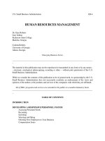
ADC’s traditional splitter/combiner products mount in a universal horizontal chassis configuration.
As shown in Figure 1, the universal chassis accommodates 2x1, 4x1, and 8x1 splitter/combiner or
directional coupler modules, and can be any desired combination.
All chassis are 1.75 inches high and mount in 19-inch equipment racks or 23-inch equipment
racks with extender brackets (ordered separately).
Figure 1
Universal Panel Mounting Space Required Per Module
2:1
Splitter/
Combiner
or
Directional
Coupler
4:1
Splitter/
Combiner
8:1
Splitter/
Combiner
Rear View
Although not shown in Figure 1, a cable tie bar is located at the rear of the chassis. There are
75 Ohm F or BNC connectors mounted on the rear of the modules that, when installed into the
universal chassis, provide the interface for all coaxial connections to the network elements. The
universal chassis can support a mixed complement of splitter/combiners and directional couplers.
The directional coupler occupies the same space as the 2x1 splitter/combiner.
RF Signal Management
Traditional Splitter/Combiner
Installation and Cable Management
2
www.adc.com • +1-952-938-8080 • 1-800-366-3891
5/01 • 1267
Traditional Splitter/Combiner
Traditional Splitter/Combiner
Basic Chassis Installation
Small or Stand-Alone Applications
Since the universal chassis is equipped with a cable tie bar at the rear of the chassis, all necessary hardware
to completely install the chassis in a 19-inch rack and manage the coaxial cables is provided. When
installing the universal chassis, first determine what type of mounting environment it is to be installed in.
If mounting the chassis in a 23-inch equipment rack, attach extender brackets (ordered separately) to the
chassis prior to installing the chassis in the equipment rack (see Figure 2).
Figure 2
Chassis Equipment Rack Mounting
Cable Tie Bar
Mounting
Screws (2)
Mounting
Screws (2)
TOP VIEW
23-inch Equipment Rack Mounting
Extender
Bracket
Mounting
Screws (2)
Extender
Bracket
Mounting
Screws (2)
Cable Tie Bar
Mounting
Screws (2)
Mounting
Screws (2)
TOP VIEW
19-inch Equipment Rack Mounting
3
www.adc.com • +1-952-938-8080 • 1-800-366-3891
5/01 • 1267
Traditional Splitter/Combiner
Traditional Splitter/Combiner
Basic Chassis Installation
Figure 3
Typical Splitter/Combiner Cable Routing
Rear View
Once the extender brackets have been attached to the universal chassis, position the chassis in its assigned
rack location and secure with four mounting screws (provided), two on each side. Next, install the required
type of splitter/combiner module(s) into the universal chassis. Lastly, cable the network elements to the
splitter/combiner modules. When routing the coaxial cables into the universal chassis, it is recommended
that the cabling be split between the left and right sides of the equipment rack (see Figure 3).
Figure 3 depicts a sample installation in which two 8x1 splitter/combiner modules have been installed in
the universal chassis. As shown, signal coaxial cable enters/exits each individual 8x1 module and is routed
up the equipment rack uprights.
4
www.adc.com • +1-952-938-8080 • 1-800-366-3891
5/01 • 1267
Traditional Splitter/Combiner
Traditional Splitter/Combiner
Cabinet Cable Management
For Larger Applications
Figure 4
Cabinet Cable Ring Kit
SVC-CBL-KIT-C Cable Ring Kit
Figure 5
Cabinet Cable Management
Cable Management Utilizing SCV-CBL-KIT-C Kit
In using this cabinet cable management kit, it is important to understand the type of cable routing practice
used within the office. If cables enter/exit the cabinet at the top of the cabinet and run in overhead cable
ladder, the largest 6-inch ring must be placed at the top of the bay. The 5-inch ring should be installed in
the middle of the bay with the smallest 4-inch ring towards the bottom (see Figure 4). If cabling enters/exits
the cabinet through a raised computer floor, for example, the ring locations must be inverted. Assuming
that overhead cable routing is used, cable the uppermost chassis first; route the cables through the top
cable ring closest to the top of the cabinet (see Figure 5). Cables from the next-lower chassis exit the rack
through either the top 6-inch ring or the 5-inch, depending on chassis versus ring placement. Continue
working down the cabinet, routing cables through the ring most appropriate for the chassis location.
Route the cables from the lower chassis through the cable ring at the middle of the rack, then through the
uppermost ring at the top of the rack as shown.
Tie all cables into a bundle before routing them through the cable management rings at the top of the
rack. All cables must exit the rack through the 6-inch by 6-inch ring at the top of the cabinet.
5
www.adc.com • +1-952-938-8080 • 1-800-366-3891
5/01 • 1267
Traditional Splitter/Combiner
Traditional Splitter/Combiner
Open Rack Cable Management
84"
12"
23"
For Larger Applications
Figure 6
Open Rack Cable Tie Bar/Ring Kit
SCV-CBL-KIT-E Cable Tie Bar/ Ring
Figure 7
Typical Unequal Flange Rack with 5" Front Guard Box
Before the use of this cable management kit is discussed, a review of a few basic cable management
practices for open racks is important. Unlike an equipment cabinet which can have a footprint of 24 inches
to 30 inches in depth, an open unequal flange frame typically only provides a 12-inch or 15-inch deep
footprint (see Figure 7), including the 2-inch or 5-inch guard box.
6
www.adc.com • +1-952-938-8080 • 1-800-366-3891
5/01 • 1267
Traditional Splitter/Combiner
Traditional Splitter/Combiner
Ordering Guide
10"
For Larger Applications
When installing equipment in this type of rack, ADC recommends a minimum of 10 inches of bay
separation to accommodate the vertical routing of cable. As shown in Figure 8, all coaxial cables vertically
entering/exiting the universal chassis are routed up the sides of the unequal flange equipment rack.
Therefore, when two racks are placed side by side, additional room for cable routing must be allowed.
Note in Figure 7 that the cable bundle at the top of the equipment rack is substantially larger than at
the bottom of the bay. Had the equipment rack been mounted on a raised floor, the situation would
be inverted with the large bundle mass at the bottom of the rack. For aesthetic considerations, rack filler
kits can be purchased to hide the cable bundles when viewed from the front of the equipment racks
(see Figure 8).
Figure 7
Rear View/Coaxial Cable Routing
For Larger Applications
Note that the universal chassis cable tie bars have
been removed for clarity. The six cable tie bar/ring
assemblies should be evenly spaced to provide for
adequate bay coverage for cable management.
Once installed on the bay, the cable tie bar/ring
assemblies provide two separate channels for
routing of coaxial cables within the bay. First, the
cable tie bar portion of the assembly mimics the
cable tie bar that ships with the universal chassis
and provides cable management for coaxial cable
entering/exiting the rack. Secondly, the rings
attached to the cable tie bar provide excellent cable
management of coaxial cable routing between
universal chassis within the rack. Figure 9 provides
a top-down view depicting how coaxial cables are
routed when using the cable tie bar/ring assembly.
As with all cable management practices outlined in
this document, the universal chassis divides the
connections on the rear of the universal chassis
into two planes – left and right. Each cable bundle
is then routed either to the left or the right hand
side of the chassis. At that point, coaxial cables
entering/exiting the rack are routed via the interbay
cable routing channel, as created by the rack
uprights. Coaxial cables needing to connect to
other universal chassis modules are routed through
the intrabay cable channel, as provided by the
cable rings. Figure 10 shows a side view of the
cable routing.
7
www.adc.com • +1-952-938-8080 • 1-800-366-3891
5/01 • 1267
Traditional Splitter/Combiner
Traditional Splitter/Combiner
Open Rack Cable Management
Side View
REAR
12"
5"
5"
Cable Tie Bar/Ring
Assembly
Figure 8
Open Rack Cable Management
Intrabay Cable Routing
Interbay Cable
Routing
Traditional Splitter/Combiner
Open Rack Cable Management
Conclusion
ADC’s RF Signal Management products meet the needs of today’s broadband RF service provider. Quality of
service to the customer is quickly becoming the major differentiating factor between various service providers
– and is key to retaining current business as well as gaining additional business. Excellent cable management
practices take the worry out of lengthy troubleshooting and problem resolution.
Figure 9
Top View – Open Rack
Cable Management Detail
Figure 10
Side View – Open Rack
Cable Management Detail
Cable Tie Bar/Ring
Assembly
Universal
Chassis
Unequal Flange
Rack Upright
ADC Telecommunications, Inc., P.O. Box 1101, Minneapolis, Minnesota USA 55440-1101
Specifications published here are current as of the date of publication of this document. Because we are continuously improving our products, ADC
reserves the right to change specifications without prior notice. At any time, you may verify product specifications by contacting our headquarters
office in Minneapolis. ADC Telecommunications, Inc. views its patent portfolio as an important corporate asset and vigorously enforces its patents.
Products or features contained herein may be covered by one or more U.S. or foreign patents. An Equal Opportunity Employer
1267 5/01 Revision © 2000, 2001 ADC Telecommunications, Inc. All Rights Reserved
Web Site: www.adc.com
From North America, Call Toll Free: 1-800-366-3891, Ext. 63475 • Outside of North America: +1-952-938-8080 Fax: +1-952-946-3292
For a complete listing of ADC's global sales office locations, please refer to our web site.