Tài liệu FL1000 Fiber Termination Products Two-Door Wall Mount Boxes pdf
Bạn đang xem bản rút gọn của tài liệu. Xem và tải ngay bản đầy đủ của tài liệu tại đây (2.93 MB, 25 trang )
10/03 • 100571
600 mm Products
28
www.adc.com • +32-2-712-65-00 • +32-2-712-65-42
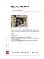
FL1000 Fiber Termination Products
Two-Door Wall Mount Boxes
12-Position Termination/Splice Wall Box
The FL1000 two-door, wall mount boxes feature a unique design and many integrated features such as:
• Multiple, configurable locking options that allow users and service providers separate access
for security
• Acceptance of strength member tie-off hardware
• Acceptance of cable clamps at each corner
Grounding screws, mounting screws, and dust caps are included with each panel. More accessories are
available on page 33.
PNT0
PNT1
13.0"
3.6"
11.2"
Swing-Out
Door
Tie
Lance
Splice Tray
(Optional)
Swing-Out
Door
Splice
Deck
Radius Limiter
(4 Places)
6pak Adapter Plate
(Optional With or
Without Pigtails)
Cable Clamp
(Optional)
Compression Fitting
(Optional)
Designation
Label
Cable Channel
(Optional)
Strength Member
Tie-Off (Optional)
24-Position Termination/Splice Wall Box
17.0"
6.2"
17.7"
Swing-Out
Door
Tie
Lance
Splice Tray
(Optional)
Swing-Out
Door
Splice
Deck
Radius Limiter
(4 places)
6pak Adapter Plate
(Optional With or
Without Pigtails)
Cable
Clamp
(Optional)
Compression Fitting
(Optional)
Designation
Label
Strength Member
Tie-Off (Optional)
48-Position Termination/Splice Wall Box
14.0"
3.6"
15.1"
Swing-Out
Door
Tie
Lance
Splice Tray
(Optional)
Swing-Out
Door
Splice
Deck
Radius Limiter
(4 Places)
6pak Adapter
Plate (Optional With
or Without Pigtails)
Cable Clamp
(Optional)
Compression Fitting
(Optional)
Designation
Label
Cable Channel
(Optional)
Strength Member
Tie-Off (Optional)
10/03 • 100571
600 mm Products
29
www.adc.com • +32-2-712-65-00 • +32-2-712-65-42
FL1000 Fiber Termination Products
Two-Door Ordering Information
FL1- __ __ __ __ __ __ __ __ - __ __ __ __ __
Wall Box Type
G 2-door, 12-position
termination/splice wall box
H 2-door, 24-position
termination/splice wall box
J 2-door, 48-position
termination/splice wall box
Splice Tray with Chip
1 Bare fusion
2 Heat shrink fusion
3 Mechanical
(elastomeric)
4 Rotary
6 FibrLok
®
7 Nortel QPAK
N None
Accessories
5 Cable clamp
6 Compression fittings
7 Bonding grounding kit
8 Strength member
tie-off
Locks
A Two A keys
B Two B keys
C One A key, one B key
D One A key
E One B key
N None
6paks not Installed into Wall
Box (with or without Fiber)
OR
1 Adapters with pigtails
(2.0 mm x 3.0 m)
2 Adapters only
N None/NA
6paks Installed into Wall Box
(with or without Fiber)*
3 Adapters with pigtails
preinstalled into wall box
(2.0 mm x 3.0 m)
4 Adapters preinstalled into
wall box
Multimode and Singlemode
6pak Adapter/Connector Type
Singlemode
Multimode
0 Blank
N None/NA
2 FC ultra polish
4ST
®
ultra polish
7 SC ultra polish
C SC duplex with
zirconia sleeves
E SC duplex
F FC angled polish
J SC angled polish
K E-2000 angled polish
L FC with zirconia sleeves
PST
®
with zirconia sleeves
R SC with zirconia sleeves
XLX.5
®
8LC
5ST
®
9SC
AFC
D SC duplex
YLX.5
®
6LC
1 2 3A 3B 3C 3D 3E 4 5 6 7 8 9
Number of splice trays
received depends on
amount of 6paks used:
1-2 6paks = 1 splice tray
4 6paks = 2 splice trays
6 6paks = 3 splice trays
8 6paks = 4 splice trays
*Use the guide above for placement of factory-installed 6paks. Place
the desired connector or adapter type (from guide above) above the
corresponding location designation of 3A, 3B, 3C, 3D or 3E. The
diagram illustrates the location of each 6pak within the bulkhead.
Enter the desired quantity
(0-9) above the
corresponding accessory.
Numerous locking options
are available for separate
user and service provider
access. Choose the
combination appropriate for
your securtiy needs.
3
E
3
D
Wall-Mount Bulkhead
Viewed from Equipment Side
Mounting
Wall Side
Door Side
3
C
3
A
3
E
3
D
3
C
3
B
How to order an FL1000 two-door wall mount box
1. Select wall box type
2. Select 6pak (with or without fiber) not installed in wall mount box (recommended for quicker availability)
OR Select 6pak (with or without fiber) installed in wall mount box
3. Select 6pak adapter type (if factory installed, choose placement in the wall mount box
4. Select splice tray with chip
5. Select number of cable clamps (0-9)
6. Select number of compression fittings (0-9)
7. Select number of bonding grounding kits (0-9)
8. Select number of strength member tie-off kits (each wall box accepts 2, maximum) (0-9)
9. Select locks
Catalog Number
10/03 • 100571
600 mm Products
30
www.adc.com • +32-2-712-65-00 • +32-2-712-65-42
FL1000 Fiber Termination Products
Two-Door Wall Mount Boxes with MTRJ Connectors
FL1- __ __ - 0 __ __ __ __ __ __ __ __ __
Box Size
Catalog Number
12 12-position
(24 fiber connections)
24 24-position
(48 fiber connections)
36 36-position
(72 fiber connections)
48 48-position
(96 fiber connections)
72 72-position
(144 fiber connections)
96 96-position
(192 fiber connections)
Type of Splice Tray
1 Bare fusion
2 Heat shrink
3 Mechanical
4 Rotary
6 Fibrlok
®
7 Nortel QPAK
8 Raychem
N None**
Locks
N None
A (2) key A
B (2) key B
C (1) key A, (1) key B
D (1) key A
E (1) key B
Fiber Connections*
012 12
024 24
036 36
048 48
072 72
096 96
144 144
192 192
Adapter Style
M MTRJ
(pass through adapters only)
S MTRJ workstation jack
(putty)
B MTRJ secure keyed jack
(blue)
G MTRJ secure keyed jack
(green)
H MTRJ secure keyed jack
(yellow)
W MTRJ secure keyed jack
(red)
12 3456789101112
Accessories***
8 Cable clamp
9 Compression fittings
10 Bonding/grounding
11 Strength member
tie-off
* Each position = 2 fiber connections (e.g., 24-position
panel fully loaded with MTRJ = 48 fiber connections).
** For interconnect only applications; right side of box
can be used as slack storage.
*** Select number of each as needed. Qty 0-9.
Dimensions H x W x D
12-position 15.5" x 20.0" x 4.1"
24-position 15.5" x 20.0" x 4.1"
36-position 23.0" x 22.2" x 5.5"
48-position 23.0" x 22.2" x 5.5"
72-position 23.0" x 22.2" x 7.0"
96-position 31.0" x 22.2" x 7.0"
Features
• Quick installation
• Compact size
• Durability
• Single catalog number ordering
• Wall boxes come preconfigured (6paks installed)
• Two-door design allows for separate user/service provider access
• Numerous locking options
• Acceptance of strength member tie-off hardware
• Acceptance of cable clamps or compression fittings at each corner
• Slack storage on left, splicing or storage on right side of box
• Available in putty
10/03 • 100571
600 mm Products
31
www.adc.com • +32-2-712-65-00 • +32-2-712-65-42
FL1000 Fiber Termination Products
One-Door Wall Mount Boxes
12-Position Termination/Splice Wall Box
The FL1000 one-door, wall mount boxes feature a unique design and many integrated features such as:
• Numerous cable tie points within the panels
• Ability to accept hasp-style locks
• Acceptance of cable clamps at each corner
Grounding screws, mounting screws, and dust caps are included with each panel. More accessories are
available on page 33.
24-Position Termination/Splice Wall Box
48-Position Splice Wall Box
6pak Adapter Plate
(Optional, With or
Without Pigtails)
Compression
Fitting
(Optional)
Splice Tray Shown
With Cover Removed
(Optional)
Swing-Out
Door
Designation
Label
Tie
Lance
Grounding Kit
Mounting Holes
Radius Limiter
(4 Places)
Splice
Deck
Cable Clamp
19.8"
1.0"
3.58"
(9.1 cm)
1.2"
12.0"
7.8"
10.2"
(25.96 cm)
15"
(38.1 cm)
6pak Adapter Plate
(Optional, With or
Without Pigtails)
Cable Clamp
Compression
Fitting
(Optional)
Splice Tray Shown
With Cover Removed
(Optional)
Swing-Out
Door
Designation
Label
Tie
Lance
Radius Limiter
(4 Places)
Splice
Deck
Grounding Kit
Mounting Holes
21.4"
3.58"
(9.1 cm)
1.2"
13.0"
8.4"
Compression
Fitting
(Optional)
Splice Tray Shown
With Cover Removed
(Optional)
Swing-Out
Door
Designation
Label
Tie
Lance
Radius Limiter
(4 Places)
Splice
Deck
Cable Clamp
15"
(38.1 cm)
Grounding Kit
Mounting Holes
21.4"
1.0"
3.58"
(9.1 cm)
1.2"
13.0"
8.4"
10/03 • 100571
600 mm Products
32
www.adc.com • +32-2-712-65-00 • +32-2-712-65-42
FL1000 Fiber Termination Products
One-Door Ordering Information
Wall Box Type
A 1-door, 12-position
termination/splice wall box
B 1-door, 24-position
termination/splice wall box
C 1-door, 48-position
splice-only wall box
Splice Tray with Chip
1 Bare fusion
2 Heat shrink fusion
3 Mechanical
(elastomeric)
4 Rotary
6 FibrLok
®
7 Nortel QPAK
N None
Accessories
5 Cable clamp
6 Compression fittings
7 Bonding grounding kit
6paks not Installed into Wall
Box (with or without Fiber)
OR
1 Adapters with pigtails
(2.0 mm x 3.0 m)
2 Adapters only
N None/NA
6paks Installed into Wall Box
(with or without Fiber)*
3 Adapters with pigtails
preinstalled into wall box
(2.0 mm x 3.0 m)
4 Adapters preinstalled into
wall box
Multimode and Singlemode
6pak Adapter/Connector Type
Singlemode
Multimode
0 Blank
N None/NA
2 FC ultra polish
4ST
®
ultra polish
7 SC ultra polish
C SC duplex with
zirconia sleeves**
E SC duplex**
F FC angled polish
J SC angled polish
K E-2000 angled polish
L FC with zirconia sleeves
PST
®
with zirconia sleeves
R SC with zirconia sleeves
XLX.5
®
8LC
5ST
®
9SC
D SC duplex**
AFC
YLX.5
®
6LC
How to order an FL1000 one-door wall mount box
1. Select wall box type
2. Select 6pak (with or without fiber) not installed in wall mount box
OR Select 6pak (with or without fiber) installed in wall mount box
3. Select 6pak adapter type (if factory installed, choose placement in the wall mount box)
4. Select splice tray with chip
5. Select number of cable clamps (0-9)
6. Select number of compression fittings (0-9)
7. Select number of bonding grounding kits (0-9)
1 2 3A 3B 3C 3D 4 5 6 7 8
Number of splice trays
received depends on
amount of 6paks used:
1-2 6paks = 1 splice tray
3-4 6paks = 2 splice trays
Wall Box Type C =
4 splice trays
*Use the guide to the right for
placement of factory-installed 6paks.
Place the desired connector or
adapter type (from guide above)
above the corresponding location
designation of 3A, 3B, 3C or 3D. The
diagram illustrates the location of
each 6pak within the bulkhead.
**Requires zip cable
Enter the desired quantity
(0-9) above the
corresponding accessory.
3
C
3
A
Wall-Mount
Bulkhead
idf
Mounting
Wall Side
Door Side
3
D
3
B
Catalog Number
FL1-
__ __ __ __ __ __
N N
__ - __ __ __
10/03 • 100571
600 mm Products
33
www.adc.com • +32-2-712-65-00 • +32-2-712-65-42
FL1000 Fiber Termination Products
FL2-6PMMSC
FL2-6PMMDSC
FL2-6PMMST
FL2-6PMMFC
FL2-6PMMLX
FL2-6PMMLC
FL2-6PSMSC
FL2-6PSMDSC
FL2-6PSMST
FL2-6PSMFC
FL2-6PSMSC-Z
FL2-6PSMDSC-Z
FL2-6PSMST-Z
FL2-6PSMFC-Z
FL2-6PSMASC
FL2-6PSMAFC
FL2-6PSMAE2
FL2-6PSMALX
FL2-6PSMLC
SC
Duplex SC
ST
®
FC
LX.5
®
LC
SC
Duplex SC
ST
®
FC
SC
(with zirconia sleeve)
Duplex SC
(with zirconia sleeve)
ST
®
(with zirconia sleeve)
FC
(with zirconia sleeve)
SC angled 8°
FC angled 8°
E-2000 angled 8°
LX.5
®
LC
Multimode Catalog Number
(62.5/125)
6paks without fiber
FL1-6P9BC003
FL1-6PDBC003
FL1-6P5BC003
FL1-6PABC003
FL1-6PYBC003
FL1-6P6BC003
FL1-6P7SC003
FL1-6PESC003
FL1-6P4SC003
FL1-6P2SC003
FL1-6PRSC003
FL1-6PCSC003
FL1-6PPSC003
FL1-6PLSC003
FL1-6PJSC003
FL1-6PFSC003
FL1-6PKSC003
FL1-6PXBC003
FL1-6P8SC003
SC
Duplex SC
ST
®
FC
LX.5
®
LC
SC
Duplex SC
ST
®
FC
SC
(with zirconia sleeve)
Duplex SC
(with zirconia sleeve)
ST
®
(with zirconia sleeve)
FC
(with zirconia sleeve)
SC angled 8°
FC angled 8°
E-2000 angled 8°
LX.5
®
LC
Multimode Catalog Number
(62.5/125)
6paks with fiber
Singlemode
Singlemode
Flexibility for future growth:
To add capacity to an existing
FL1000 panel, simply order the
appropriate 6pak.
6pak Adapter Packs
Accessories
6pak without fiber
6pak with fiber
Description
Compression fitting
Radius limiters (set of 2 for use with rack mount panels)
Strength member tie-off kit
NEMA box access tool
Cable clamp
Bonding grounding kit
Lock and Key Type A
Lock and Key Type B
Mini-splice trays
(used only in 12-position, wall mount box)
Bare fusion
Heat shrink fusion
Rotary
FibrLok
®
Northern Telecom QPAK
Standard splice trays
Bare fusion
Heat shrink fusion
Mechanical (Elastomeric)
Rotary
FibrLok
®
Northern Telecom QPAK
Raychem universal chip
Catalog Number
FL1-ACC001
FL1-ACC002
FL1-ACC003
ACE/AGX-KEY
FL2-ACC007
FL2-ACC006
IPA-K1
IPA-K2
FL1-M-FT
FL1-M-HS
FL1-M-RT
FL1-M-3M
FL1-M-NT
FST-FT
FST-HS
FST-MT
FST-RT
FST-3M
FST-NT
FST-RCM
Ordering Information
10/03 • 100571
600 mm Products
34
www.adc.com • +32-2-712-65-00 • +32-2-712-65-42
FL2000 System
Introduction
Single Fiber Access Swing-out Bulkhead Allows Full Access
The FL2000 System is a flexible, modular and economical series of fiber products
designed for mounting into ETSI cabinets with either 19" or ETSI mounting.
FL2000 Rack Mount
Termination Panel (Empty)
FL2000 Rack Mount
Termination Panel with IFC
FL2000 Rack Mount
Termination/Splice Panel
(Empty)
6pak Adapter Packs
Features
• A complete line of modular panels and boxes, developed for cabinet,
rack and wall mounting.
• Fully adaptable for large or small main distribution frame (MDF),
intermediate distribution frame (IDF) or telephone closet (TC) applications.
• Designed for 19-inch (48.26 cm) EIA rack or cabinet environment found
in many enterprise networks; optional brackets are available to
accommodate ETSI rack or cabinet mounting.
• Provides termination, splicing and storage capabilities for in-building
cables, outside plant cables and fiber optic terminal (FOT) equipment
patch cords.
• Modular design offers maximum flexibility to satisfy both current needs
and future growth requirements.
• A full line of options and accessories ensures compatibility with existing
optical equipment.
• FL2000 systems accommodate Value-Added Modules, adding flexibility
and functionality to the optical transport systems. Splitters, wavelength
division multiplexers (WDMs) and other optical components can be easily
incorporated.
• All FL2000 panels and boxes accommodate the modular FL2000 6pak
plug-ins. 6paks are available in all connector styles and can be ordered
as needed.
• ADC’s patented removable angled retainers allow easy access for single
fiber maintenance.
• FL2000 panels and boxes feature superior vertical cable protection
and management.
• Rack mount panels are hinged on one side, allowing full access to the
rear of the front plate and the interior of the panel.
• Rack mount panels are equipped with mounting brackets to provide
12.7cm (5-inch) recess mounting; mounting brackets are available for
virtually any mounting application.
• Rack mount panels can be wall mounted.
• The new FL2000 splice wheel allows easy roll-up of pigtail and buffer
tube lengths and superior bend radius protection.
• The FL2000 splice deck is available to complete existing installations.
10/03 • 100571
600 mm Products
35
www.adc.com • +32-2-712-65-00 • +32-2-712-65-42
Features
• Available with factory-installed multifiber
intrafacility cable (IFC) or OSP cable
• Panels with multifiber cable attached ship as a
single unit with cable clamp installed
• Panels come equipped with customer specified
number of adapters, retainers, connectors,
cable type and cable length
• Panels with multifiber cable attached save
costly installation time
• Simplifies ordering process by allowing one
part number for the panel, adapters,
connectors and cable
• Multiple mounting styles available
Fiber Panel Data
• Termination
• Preloaded with multifiber cable
FL2000 Rack or Cabinet Mount Panels
Preconfigured Termination Panels with Multifiber Cable
Ordering information appears on next page.
10/03 • 100571
600 mm Products
36
www.adc.com • +32-2-712-65-00 • +32-2-712-65-42
36
FL2000 Rack or Cabinet Mount Panels
Preconfigured Termination Panels with Multifiber Cable
SC
Duplex SC
ST
®
LX.5
®1
LC
1
Ultra PCFC
FC with zirconia adapter
FC 8° angled polish
Ultra PCSC
SC with zirconia adapter
SC 8° angled polish
Duplex SC
Ultra PCST
ST
®
with zirconia adapter
E-2000 8° angled polish
LX.5
®1
LC
1
FC Hybrid (FC connector on front;
SC connector on back of bulkhead)
ST
®
Hybrid (ST
®
connector on front;
SC connector on back of bulkhead)
S
M
Singlemode
Multimode
Panel Type
1
2
3
4
7
9
12-position 1.75" (4.45cm) (1RU)
24-position 3.5" (8.89 cm) (2RU)
36-position 5.25" (13.34 cm) (3RU)
48-position 5.25" (13.34 cm) (3RU)
72-position 8.75" (22.23 cm) (5RU)
96-position 10.5" (26.67 cm) (6RU)
Nominal Capacity Panel Height
Multimode
9
D
5
Y
6
Singlemode
2
L
F
7
N
J
E
4
P
K
X
8
1
3
Connector Style
1
2
3
4
7
9
A
Z
Y
X
W
12
24
36
48
72
96
144
2 x 12
2 x 24
2 x 36
2 x 48
Cable Size
Multimode
C
Singlemode
A
F
G
H
J
K
M
T
L
IFC stranded 62.5/125
IFC stranded riser-rated
Plenum stranded
OSP single armor stranded
Indoor-outdoor stranded
OSP dielectric stranded
IFC stranded Maxi-Strip
IFC ribbon riser-rated
OSP dielectric ribbon
OSP armored ribbon
Cable Type
XXX Cable length (meters)
Length in Meters
A
B
C
D
E
F
H
19" (48.26 cm) standard
(19.6" [49.78 cm] overall)
19" (48.26 cm) maximum
(19" [48.26 cm] overall)
19" (48.26 cm) flush mount
23" (58.42 cm) centered
23" (58.42 cm) with oversized VCG
ETSI flush mount
600 mm
Mounting Style
2
U
D
Up
Down
Cable Exit Direction
FL2 - __ __ __ __ __ __ __ __ __ - __ __ __ __
Catalog Number
0
0
1
LX.5
®
and LC connectors and adapters double
the capacity of the panel by terminating two fibers
at each adapter.
2
Mounting kit shipped unattached, if other than
standard mounting style.
0
1
2
5
6
Standard
Hole Plug
Screwdriver
K1 Lock
K2 Lock
Latch Type
Please see pages 49-51 for mounting instructions.
10/03 • 100571
600 mm Products
37
www.adc.com • +32-2-712-65-00 • +32-2-712-65-42
37
FL2000 Rack or Cabinet Mount Panels
Preconfigured Termination Panels with Pigtails
R Termination only
Panel Type
1
2
3
4
7
9
12-position 1.75" (4.45 cm) (1U)
24-position 3.5" (8.89 cm) (2U)
36-position 5.25" (13.34 cm) (3U)
48-position 5.25" (13.34 cm) (3U)
72-position 8.75" (22.23 cm) (5U)
96-position 10.5" (26.67 cm) (6U)
Nominal Capacity Panel Height
1
LX.5
®
and LC connectors and adapters double the capacity
of the panel by terminating two fibers at each adapter.
2
For use with LX.5
®
and LC.
3
Mounting kit shipped unattached, if other than standard
mounting style.
FL2 -
Catalog Number
123
000-
4 5 6 7 8 9 10 11
A
P
H
R
K
Y
Adapters only
6-fiber softwall bundle
6-fiber Maxi-Strip
12-fiber ribbon
12-fiber softwall bundle
2
12-fiber Maxi-Strip
2
0
1
2
5
6
Latch
Hole plug
Screwdriver
K1 lock
K2 lock
Latch Type
12
Pigtail or Adapter Type
Number of
Ports
Loaded
A
B
C
D
E
F
H
19" (48.26 cm) standard
(19.6" [49.78 cm] overall)
19" (48.26 cm) maximum
(19" [48.26 cm] overall)
19" (48.26 cm) flush mount
23" (58.42 cm) centered
23" (58.42 cm) with oversized VCG
ETSI flush mount
600 mm
Mounting Style
3
0
SC
Duplex SC
ST
®
LX.5
®1
LC
1
Ultra PCFC
FC with zirconia adapter
FC 8° angled polish
Ultra PCSC
SC with zirconia adapter
SC 8° angled polish
Duplex SC
Ultra PCST
ST
®
with zirconia adapter
E-2000 8° angled polish
LX.5
®1
LC
1
FC hybrid (FC connector on front;
SC connector on back of bulkhead)
ST
®
hybrid (ST
®
connector on front;
SC connector on back of bulkhead)
Multimode
9
D
5
Y
6
Singlemode
2
L
F
7
N
J
E
4
P
K
X
8
1
3
Connector Style
4.95"
(12.58 cm)
10.14"
(25.76 cm)
19.60"
(49.79 cm)
5.25"
(13.34 cm)
10/03 • 100571
600 mm Products
38
www.adc.com • +32-2-712-65-00 • +32-2-712-65-42
38
FL2000 Rack or Cabinet Mount Panels
Preconfigured Termination/Splice Panels with Pigtails
PNT1
PNT1
10.14"
(25.76 cm)
4.95"
(12.58 cm)
19.60"
(49.79 cm)
5.25"
(13.34 cm)
C Termination/Splice
Panel Type
1
2
4
7
9
12-position 3.5" (8.89 cm) (2U)
24-position 5.25" (13.34 cm) (3U)
48-position 8.75" (22.23 cm) (5U)
72-position 14.00" (35.56 cm) (8U)
96-position 17.50" (44.45 cm) (10U)
Nominal Capacity Panel Height
FL2 -
Catalog Number
123
0-
4 5 6 7 8 9 10 11
0
M
W
1
2
3
7
8
None or N/A
Mechanical (wheel)
Heat shrink
fusion (wheel)
Bare fusion (deck)
Heat shrink
fusion (deck)
Mechanical (deck)
Raychem
universal (deck)
Nortel (deck)
Splice Type
12
M
N
Mechanical (wheel)
Nortel (wheel)
Splice Type
2
Number
of Ports
Loaded
Number of
Splice Decks
A
B
C
D
E
F
H
19" (48.26 cm) standard
(19.6" [49.78 cm] overall)
19" (48.26 cm) maximum
(19" [48.26 cm] overall)
19" (48.26 cm) flush mount
23" (58.42 cm) centered
23" (58.42 cm) with
oversized VCG
ETSI flush mount
600 mm
Mounting Style
3
1
LX.5
®
and LC connectors and adapters
double the capacity of the panel by
terminating two fibers at each adapter.
2
For use with LX.5
®
and LC.
3
Mounting kit shipped unattached if other
than standard mounting style.
0
2
1 clamp (standard)
2 clamps
Number of Cable Clamps
0
1
2
5
6
Latch
Hole plug
Screwdriver
K1 lock
K2 lock
Latch Type
A
P
H
R
K
Y
Adapters only
6-fiber softwall
bundle
6-fiber Maxi-Strip
12-fiber ribbon
12-fiber softwall
bundle
2
12-fiber Maxi-
Strip
2
Pigtail or Adapter Type
SC
Duplex SC
ST
®
LX.5
®1
LC
1
Ultra PCFC
FC with zirconia adapter
FC 8° angled polish
Ultra PCSC
SC with zirconia adapter
SC 8° angled polish
Duplex SC
Ultra PCST
ST
®
with zirconia adapter
E-2000 8° angled polish
LX.5
®1
LC
1
FC hybrid (FC connector on front;
SC connector on back of bulkhead)
ST
®
hybrid (ST
®
connector on front;
SC connector on back of bulkhead)
Multimode
9
D
5
Y
6
Singlemode
2
L
F
7
N
J
E
4
P
K
X
8
1
3
Connector Style
10/03 • 100571
600 mm Products
39
www.adc.com • +32-2-712-65-00 • +32-2-712-65-42
FL2000 Rack Mount Panels
Termination Panels with MTRJ Connectors
FL2- __ __ __ 0 __ __ __ A 0 - 0 __ __ 0
Panel Type
Catalog Number
R Termination only rack mount
Nominal Capacity/Panel Height
1 12-position putty/1.75" (1RU)
2 24-position putty/3.5" (2RU)
3 36-position putty/5.25" (3RU)
4 48-position putty/5.25" (3RU)
7 72-position putty/8.75" (5RU)
9 96-position putty/10.5" (6RU)
A 12-position black/1.75" (1RU)
B 24-position black/3.5" (2RU)
C 36-position black/5.25" (3RU)
D 48-position black/5.25" (3RU)
E 72-position black/8.75" (5RU)
F 96-position black/10.5" (6RU)
Adapter Style
M MTRJ
(pass through adapters only)
S MTRJ workstation jack (putty)
B MTRJ secure keyed jack (blue)
G MTRJ secure keyed jack (green)
H MTRJ secure keyed jack (yellow)
W MTRJ secure keyed jack (red)
Pigtail or Adapter Type
A Adapters only
Latch Type
0 Standard
1 Hole plug
2 Screwdriver
3 K3 lock
4 K4 lock
5 K1 lock
6 K2 lock
Mounting Style
A 19" standard
(19.6" overall)
B 19" maximum
(19.0" overall)
C 19" flush mount
D 23" centered
E 23" oversized VCG
Number of Cable Clamps
0 0 clamps (standard)
Fiber Connections*
012 12
024 24
036 36
048 48
072 72
096 96
144 144
192 192
123 45678 9101112
* Each position = 2 fiber
connections (e.g., 24-
position panel fully loaded
with MTRJ = 48 fiber
connections).
Features
• Superior vertical cable protection and management
• Panels come preconfigured (6paks installed)
• Panels hinged on one side, allowing full access to the rear of the front
plate and the interior of the panel
• Equipped with mounting brackets to provide 5-inch recess mounting;
mounting brackets available for virtually any mounting application
• Complete line of accessories, including locks for security
10/03 • 100571
600 mm Products
40
www.adc.com • +32-2-712-65-00 • +32-2-712-65-42
Features
• Mounting
- 19-inch (48.26 cm) EIA rack or cabinets,
standard 12.7 cm ( 5") recess
- Wall mounting option available
- Other mounting kits available.
Please see pages 49-51.
• Hinged on left front side; allows full access to
rear of front plate and interior of panel
• FL2000 6pak adapter packs ordered separately
• Constructed of high strength aluminum
• Equipped with removable metal doors with
Plexiglas windows
• Designation labels included with each panel
• Complete line of accessories including locks
for security
Fiber Panel Data
• Fiber capacity*: 12, 24, 36, 48, 72 & 96
• Termination
• Pigtail storage
4.95"
(12.58 cm)
10.14"
(25.76 cm)
19.60"
(49.79 cm)
5.25"
(13.34 cm)
FL2000 Rack or Cabinet Mount Panels
Empty Termination Panels
Description
Rack or cabinet mount termination panel
Includes vertical cable management trough
12-fiber capacity
24-fiber capacity
36-fiber capacity
48-fiber capacity
72-fiber capacity
96-fiber capacity
Accessories
Wall mount bracket -
Needed for 12 fiber capacity panel only
Cable clamp kit -
One per cable recommended
Outer diameter .2" to .8"
Outer diameter .7" to 1.0"
Cable clamp kit for 12 fiber capacity
panel only
Bonding/grounding kit
For mounting kits and additional
accessories, see pages 47-51
Catalog Number
1
FL2-12RPNL
FL2-24RPNL
FL2-36RPNL
FL2-48RPNL
FL2-72RPNL
FL2-96RPNL
FL2-ACC008
FL2-ACC007
FL2-ACC021
FL2-ACC033
FL2-ACC006
Panel Height
4.45 cm (1.75")
8.89 cm (3.50")
13.34 cm (5.25")
13.34 cm (5.25")
22.23 cm (8.75")
26.67 cm (10.50")
Ordering Information
1.75" (4.45 cm)
3.50" (8.89 cm)
5.25" (13.34 cm)
8.75" (22.23 cm)
10.50" (20.67 cm)
1
Panels with right front hinge and VCG are also available, although they are not standard products.
To order a panel with right front hinge and VCG , add “-R” after the catalog number.
Example: FL2-12RPNL-R.
24-Fiber Capacity
72-Fiber Capacity
96-Fiber Capacity
*All panels can double capacity with LX.5
®
adapters
10/03 • 100571
600 mm Products
41
www.adc.com • +32-2-712-65-00 • +32-2-712-65-42
SPLICE CHIP(S)
(HEAT SHRINK
SHOWN)
SPLICE
DECK
TOP
SIDE
BOTTOM
SIDE
CLEAR
COVERS
Splice Wheel with
Splice Chip
Splice Deck with
Splice Chip
Catalog Number
1
FL2-48SPNL2
FL2-96SPNL2
FL2-144SPNL2
FST-DRS12-HS
FST-DRS12-MT
FST-DRS24-NT
FL2-48SPNL
FL2-96SPNL
FL2-144SPNL
FL2-RSPLCE-HS
FL2-RSPLCE-MT
FL2-RSPLCE-FT
FL2-RSPLCE-NT
FL2-ACC007
FL2-ACC021
Panel Height
3.5" (8.89 cm)
7" (17.78 cm)
8.75" (22.23 cm)
3.5" (8.89 cm)
7" (17.78 cm)
8.75" (22.23 cm)
Ordering Information
Description
Splice panel for splice wheel
(Accepts splice wheel only)
48 fiber capacity
96 fiber capacity
144 fiber capacity
Splice wheel with splice chip
Heat shrink fusion
Mechanical
Nortel
Splice panel for splice deck for existing installations
(Also accepts splice wheel)
48 fiber capacity
96 fiber capacity
144 fiber capacity
Splice deck with splice chip for existing
installations
Heat shrink fusion
Mechanical
Bare fusion
Nortel
Cable clamp kit (kit of 1)
Outer diameter .2" to .8" (.5 cm to 2 cm)
Outer diameter .7" to 1.0" (1.8 cm to 2.54 cm)
FL2000 Rack or Cabinet Mount Panels
Empty Splice Panels
Features
• Offers combination of splicing protection and
associated fiber/pigtail storage
• Splice panel can be mounted in conjunction
with any FL2000 termination panel or as a
stand-alone splice panel
• Occupies same footprint and offers same
mounting options as FL2000 termination panels
• Accepts the new ADC splice wheel for efficient
management of fiber cable and splice protection
• Accepts the traditional ADC splice deck
Fiber Panel Data
• Fiber capacity: 48, 96, 144
• Splice
• Pigtail storage
For mounting kits and additional accessories, see pages 47-51.
1
Panels with right front hinge and VCG are also available, although they are not standard product. To
order a panel with right VCG, add “-R” after the catalog number. Example: FL2-48SPNL-R.
3.50"
(8.89 cm)
10.14"
(25.76 cm)
4.95"
(12.58 cm)
19.60"
(49.79 cm)
10/03 • 100571
600 mm Products
42
www.adc.com • +32-2-712-65-00 • +32-2-712-65-42
Catalog Number
1
FL2-12TS350
FL2-24TS525
FL2-48TS875
FL2-72TS140
FL2-96TS175
FST-DRS12-HS
FST-DRS12-MT
FST-DRS24-NT
FL2-RSPLCE-HS
FL2-RSPLCE-MT
FL2-RSPLCE-FT
FL2-RSPLCE-NT
Panel Height
3.5" (8.89 cm)
5.25" (13.34 cm)
8.75" (22.23 cm)
14" (35.56 cm)
17.5" (44.45 cm)
Ordering Information
FL2000 Rack or Cabinet Mount Panels
Empty Termination/Splice Panels
Features
• Mounting
- 19-inch (48.26 cm) EIA racks or cabinets,
standard 5-inch (12.7 cm) recess
- Wall mounting option available
- Other mounting kits available. Please see
pages 49-51
• Hinged on left front side for complete access
to interior of termination section
• Ability to quickly and easily configure, utilizing
the 6pak assemblies (ordered separately)
• Complete line of accessories including locks
for security
• Uses ADC splice wheels or splice decks
Fiber Panel Data
• Termination
• Splice
• Pigtail storage
Description
Termination/splice panel
12-position
24-position
48-position
72-position
96-position
Splice wheel with splice chip
Heat shrink fusion
Mechanical
Nortel
Splice eeck with splice chip
Heat shrink fusion
Mechanical
Bare fusion
Nortel
5.25"
(13.34 cm)
19.60"
(49.79 cm)
10.14"
(25.76 cm)
4.95"
(12.58 cm)
1
Panels with right front hinge and VCG are also available, although they are not standard product.
To order a panel with right front hinge and VCG, add “-R” after the catalog number.
Example: FL2-24TS525-R.
48-Position
96-Position
24-Position
10/03 • 100571
600 mm Products
43
www.adc.com • +32-2-712-65-00 • +32-2-712-65-42
FL2000 Slack Storage Solutions
Features
• Provides jumper storage for 3 mm patch cords
– one patch cord per disk
• Stores 3.8 meters (12.5') of patch cord in
each disk
Fiber Panel Data
• Patch cord storage
• Rack/cabinet mount
• Wall mount
10.14"
(25.76 cm)
4.95"
(12.58 cm)
5.25"
(13.34 cm)
19.60"
(49.79 cm)
ROTATE TO
REMOVE SLACK
Catalog Number
FL2-16FSD525
FL2-28FSD875
Dimensions (HxWxD)
5.25" x 19" x 10.19"
(13.34 x 48.26 x 25.81 cm)
8.75" x 19" x 10.19"
(22.23 x 48.26 x 25.81 cm)
Ordering Information
Description
Fiber Storage Disk
16 disks
24 disks
Fiber Storage Disk
Features
• Provides jumper storage for 3 mm patch cords
• Stores 33 m (110') of patch cord in each tray
Fiber Panel Data
• Patch cord storage
• Rack/cabinet mount
Catalog Number
FL2-CST60525
Dimensions (HxWxD)
5.25" x 19" x 10.19"
(13.34 x 48.26 x 25.81 cm)
Ordering Information
Description
Fiber Storage Tray
6 trays
Fiber Storage Tray
4.95 in
(12.58 cm)
10.18 in
(25.86 cm)
19.60 in
(49.79 cm)
5.25 in
(13.34 cm)
10/03 • 100571
600 mm Products
44
www.adc.com • +32-2-712-65-00 • +32-2-712-65-42
FL2000 Slack Storage Solutions
Features
• Mounts horizontally in a bay to manage
jumper storage
• May be modified for flush or wall mount
applications
• Stores up to 75 meters of cable
19.60"
(49.79 cm)
5.25"
(13.34 cm)
4.95"
(12.58 cm)
Horizontal Interbay Management Panel
Catalog Number
FL2-HZSTORE
FL2-HZSTORE-600
FL2-HZSTORE-FLMT
FL2-HZSTORE-WMNT
Description
Horizontal interbay management panel
Horizontal interbay management panel for 600 mm
centered mounting
Horizontal interbay management panel for flush
mounting
Wall bracket for wall mounting
Catalog Number
FL2-2RSTORE
FL2-6RSTORE
FL2-TR2000
Features
• Mounts with FL2000 termination panels
to provide jumper storage
• Wall, rack, or cabinet mount
• Utilizes unique storage decks for patch
cord storage
• Each storage deck accommodates up to
32 meters (105') of 3 mm cable
Description
Storage deck panels
(storage decks ordered separately)
2 storage deck capacity;
3.5" x 19" x 10.19"
(8.89 x 48.26 x 25.81 cm)
6 storage deck capacity;
8.75" x 19" x 10.19"
(22.23 x 48.26 x 25.81 cm)
Storage deck
Storage Deck Top View
FL2000 Storage Deck Panel Front View
4.95"
(12.58 cm)
10.14"
(25.76 cm)
3.50"
(8.89 cm)
19.60"
(49.79 cm)
Storage Deck Panel
Ordering Information
Ordering Information
10/03 • 100571
600 mm Products
45
www.adc.com • +32-2-712-65-00 • +32-2-712-65-42
45
Ordering Information
Features
• Completely interchangeable between FL2000
panel and wall box products
• Can be ordered with all standard types of
simplex and duplex single and multimode
adapters and connectors
• Feature ADC’s patented removable angled
retainers which provide superior fiber
management
• No tools required to install into FL2000 boxes
or panels
• Can be ordered with adapters only, or for
quick and easy installation, with preterminated
3 meter (9.84') or 5 meter (16.4') pigtails
6pak Blank Plug-In
FL2000 6pak Adapter Packs
6pak (shown with
singlemode simplex adapters)
6pak (shown with
mulitmode simplex adapters)
6pak (shown with
singlemode duplex adapters)
6pak (shown with
multimode duplex adapters)
6pak (shown with
multimode LX.5
®
adapters)
6pak (shown with
singlemode LX.5
®
adapters)
Description
Multimode
SC
ST
®
FC
SC (duplex)
SC, zirconia
ST
®
, zirconia
FC, zirconia
LX.5
®
LC
Singlemode
SC
ST
®
FC
SC (duplex)
FC with 8° angled polish
SC with 8° angled polish
SC, zirconia
ST
®
, zirconia
FC, zirconia
E-2000, angled polish
LX.5
®
LC
Hybrid: FC front, SC back
Hybrid: ST
®
front, SC back
6pak blank plug-in
Catalog Number
FL2-6PMMSC
FL2-6PMMST
FL2-6PMMFC
FL2-6PMMDSC
FL2-6PMMSC-Z
FL2-6PMMST-Z
FL2-6PMMFC-Z
FL2-6PMMLX
FL2-6PMMLC
FL2-6PSMSC
FL2-6PSMST
FL2-6PSMFC
FL2-6PSMDSC
FL2-6PSMAFC
FL2-6PSMASC
FL2-6PSMSC-Z
FL2-6PSMST-Z
FL2-6PSMFC-Z
FL2-6PSMAE2
FL2-6PSMALX
FL2-6PSMLC
FL2-6PSMFC/SC
FL2-6PSMST/SC
FL2-6PBLNK
10/03 • 100571
600 mm Products
46
www.adc.com • +32-2-712-65-00 • +32-2-712-65-42
46
Features
• Available with preterminated 3 meter (9.84')
or 5 meter (16.4') pigtails
• Pigtails consist of a single outer jacket
containing six color-coded 900 µm fibers
• One end of pigtail terminated to chosen
connector style and installed into the 6pak
adapter pack
• ADC recommends specific breakouts for panel
and wall mount box products
• Saves installation time
Multimode Pigtails and Adapters
FL2 - 6P __ __ __ __ __ __ __
Catalog Number
Fiber Type
C
D
Stranded
Maxi-Strip
Length (in meters)
03W
05R
3 m (9.84') pigtail
for wall mount boxes
5 m (16.4') pigtail
for rack mount panels
6
FL2 - 6P __ __ __ __ __ __ __
Catalog Number
Length (in meters)
03W
05R
3 m (9.84') pigtail
for wall mount boxes
5 m (16.4') pigtail
for rack mount panels
6
Fiber Size
Singlemode
Fiber Size
Multimode
Connector Style
5
9
A
D
Y
6
B
C
ST
®
SC
FC
Duplex SC
LX.5
®
1
LC
1
Multimode 62.5/125
Multimode 50/125
S
CB
S
Singlemode
Connector Style
Duplex SC
Ultra PCFC
Ultra PCST
Ultra PCSC
PCFC 8° angled polish
PCSC 8° angled polish
E-2000 angled polish
LX.5
®
1
LC
1
FC hybrid (FC connector on front;
SC connector on back of bulkhead)
ST
®
hybrid (ST
®
connector on front;
SC connector on back of bulkhead)
E
2
4
7
F
J
K
X
8
1
3
FL2000 6pak with
SC adapters and pigtails
Singlemode Pigtails and Adapters
1
LX.5
®
and LC 6paks are loaded
with 12 fiber pigtails
1
LX.5
®
and LC 6paks are loaded with
12 fiber pigtails
FL2000 6pak Adapter Packs
10/03 • 100571
600 mm Products
47
www.adc.com • +32-2-712-65-00 • +32-2-712-65-42
Locks
Catalog Number
IPA-K1
IPA-K2
UEGP-7PW
FL2-ACC011
FL2-ACC012
FL2-ACC051
FL2-ACC006
FL2-ACC007
FL2-ACC021
FL2-ACC033
FL2-BLNKVCG0350
FL2-BLNKVCG0875
FL2-BLNKVCG1050
FL2-BLNKFULL0350
FL2-BLNKFULL0525
FL2-BLNKFULL0700
FL2-BLNKFULL0875
FL2-BLNKFULL1050
Ordering Information
Description
Locks for rack mount panels
Key lock #1; includes lock and key #1
Key lock #2; includes lock and key #2
End guards
7' H x 12" W x 29/16" D; right or left side;
putty white
Lower cable trough
14" H x 19" W x 5" D
7" H x 19" W x 5" D
7" H x 600 mm (23.6") x 5" D
Bonding/grounding kit – kit of 1
Cable clamp kit – kit of 1
Outer diameter .2" to .8"
Outer diameter .7 to 1.0"
Cable clamp kit – For use with 12 fiber
termination or termination/splice panels
Blank VCG to add cable management to
frame not fully loaded
3.5" (8.89 cm)
8.75" (22.23 cm)
10.5" (26.67 cm)
Blank VCG with blank panel for aesthetics
3.5" (8.89 cm)
5.25" (13.34 cm)
7.0" (17.78 cm)
8.75" (22.23 cm)
10.5" (26.67 cm)
12"
7'
2.5"
CLAMP
BRACKET
RUBBER
GROMMETS
CLAMP
YOKES (2)
PLATE
NUTS (2)
COVER
End Guard
UEGP-7PW
14" Lower Cable Trough
FL2-ACC011
7" Lower Cable Trough
FL2-ACC012
Bonding/Grounding Kit
Cable Clamp Kit
Blank VCG
FL2-BLNKFULL0875
FL2000 Rack Mount Panels
Accessories
10/03 • 100571
600 mm Products
48
www.adc.com • +32-2-712-65-00 • +32-2-712-65-42
Catalog Number
E-501-L139
FL2-EUROIMP-26-600-A
FL2-EUROIMP-67
FL2-EUROIMP-REAR
Ordering Information
Description
Interbay Management Panel (IMP) for 19"
or 23" (48.26 or 58.42 cm) racks
7' x 5"
Interbay Management Panels (IMP) and
Inner IMPs for 600 mm and 800 mm
cabinets and racks
26" (66.04 cm) high IMP for 600 mm
racks/cabinets
Full IMP for use in 800 x 800 mm cabinet
with 19" (48.26 cm) mounting
Full IMP to install on rear side of 600 x
600 mm cabinet
Interbay Management Panel
E-501-L139
FL2000 Rack Mount Panels
Accessories
10/03 • 100571
600 mm Products
49
www.adc.com • +32-2-712-65-00 • +32-2-712-65-42
5.00"
15.912"
(40.42 cm)
17.50"
(44.45 cm)
(12.70 cm)
5.00"
(12.70 cm)
(4.93 cm)
1.94"
6.65"
(16.89 cm)
(47.82 cm)
18.83"
Rear Guard Box
(optional with some racks)
Rack shown
as reference
Catalog Number
FL2-FLMT0175
FL2-FLMT0350
FL2-FLMT0525
FL2-FLMT0700
FL2-FLMT0875
FL2-FLMT1050
Panel Height
1.75" (4.45 cm)
3.5" (8.89 cm)
5.25" (13.34 cm)
7" (17.78 cm)
8.75" (22.23 cm)
10.5" (26.67 cm)
Ordering Information
Description
Flush Mount
Allows 1", 2" or 4" (2.54, 5.08 or 10.16 cm)
recess mounting
Kit includes: new vertical cable guide and
mounting flanges
FL2000 Mounting Options
19" (48.26 cm) Rack Mounting
Standard Mount (as shipped)
Flush Mount
Features
• Panels typically shipped from factory equipped
for this mounting
17.50"
(44.45 cm)
(12.70 cm)
5.00"
(12.70 cm)
5.00"
21.88"
(55.58 cm)
19.60"
(48.26 cm)
18.31"
(46.51 cm)
Rear Guard Box
(optional with some racks)
Rack shown
for reference
Features
• Panels shipped with
- Left-side “L” bracket
- Left-side 2.5" (6.32 cm) wide vertical cable
guide (VCG)
10/03 • 100571
600 mm Products
50
www.adc.com • +32-2-712-65-00 • +32-2-712-65-42
19" Maximum Mounting
5.00"
5.00"
2.93"
4.95"
10.14"
(25.76 cm)
17.50"
(44.45 cm)
(12.58 cm)
21.88"
(55.58 cm)
(12.70 cm)
(12.70 cm)
(48.26 cm)
19.00
18.31"
(46.51 cm)
RACK SHOWN
FOR REFERENCE
REAR GUARD BOX
(OPTIONAL WITH
SOME RACKS)
New VCG with integrated mounting holes
FL2000 Mounting Options
19" (48.26 cm) Rack Mounting
Catalog Number
FL2-19MAX0175
FL2-19MAX0350
FL2-19MAX0525
FL2-19MAX0700
FL2-19MAX0875
FL2-19MAX1050
FL2-19MAX1400
FL2-19MAX1750
Panel Height
1.75" (4.45 cm)
3.5" (8.89 cm)
5.25" (13.34 cm)
7" (17.78 cm)
8.75" (22.23 cm)
10.5" (26.67 cm)
14" (35.56 cm)
17.5" (44.45 cm)
Ordering Information
Description
19" Maximum
Allows entire panel to be contained
within frame footprint
Kit includes: new vertical cable guide
with integrated mounting holes
10/03 • 100571
600 mm Products
51
www.adc.com • +32-2-712-65-00 • +32-2-712-65-42
FL2000 Mounting Options
19" ETSI and 600 mm Mounting
Catalog Number
FL2-ETEB0175
FL2-ETEB0350
FL2-ETEB0525
FL2-ETEB0700
FL2-ETEB0875
FL2-ETEB1050
FL2-ETEB1400
FL2-ETEB1700
Panel Height
1.75" (4.45 cm)
3.5" (8.89 cm)
5.25" (13.34 cm)
7.0" (17.78 cm)
8.75" (22.23 cm)
10.5" (26.67 cm)
14" (35.56 cm)
17.5" (44.45 cm)
Ordering Information
Description
19" ETSI Mounting
Kit includes mounting brackets
3.02"
5.00"
4.85"
(12.70 cm)
(12.32 cm)
(12.70 cm)
5.00"
(7.67 cm)
21.22"
(53.99 cm)
20.276"
(51.50 cm)
21.88"
(55.58 cm)
Catalog Number
FL2-600MM0175
FL2-600MM0350
FL2-600MM0525
FL2-600MM0700
FL2-600MM0875
FL2-600MM1050
FL2-600MM1400
FL2-600MM1750
Panel Height
1.75" (4.45 cm)
3.5" (8.89 cm)
5.25" (13.34 cm)
7.0" (17.78 cm)
8.75" (22.23 cm)
10.5" (26.67 cm)
14" (35.56 cm)
17.5" (44.45 cm)
Ordering Information
Description
600 mm Mounting
Kit includes mounting brackets
23.35"
(59.31 cm)
4.0"
(10.16 cm)
4.0"
(10.16 cm)
17.72"
(45.01 cm)
4.95"
(12.57 cm)
3.53"
(8.97 cm)
15.27"
(38.79 cm)
Rack Shown
as Reference
Rear Guard Box
(Optional with
Some Racks)
600 mm Mounting
19" ETSI Mounting
10/03 • 100571
600 mm Products
52
www.adc.com • +32-2-712-65-00 • +32-2-712-65-42
• Accommodates ADC VAM plug-in modules in FL2000 installations
• 19-inch rack mount
• Vertical cable guides included
19.0"
(48.26 cm)
5.0"
(12.7 cm)
5.25"
(13.34 cm)
10.14"
(25.76 cm)
FL2000 VAM 9-Position Chassis
Description
VAM chassis
4 plug-in modules
6 plug-in modules
9 plug-in modules
WideVAM
™
chassis
Chassis for 19" EIA mounting;
accommodates 4 WideVAM plug-in modules
Chassis for 19" EIA mounting for 600mm
skeleton bay; accommodates 4 WideVAM
plug-in modules
Catalog Number
FL2-4VAM525
FL2-6VAM700
FL2-9VAM105
FL2-4WVAM3RU
FL2-4WVAM3RU-600
Dimensions (HxWxD)
5.25" x 19" x 10.14"
(13.34 x 48.26 x 25.76 cm)
6" x 19" x 10.14"
(15.24 x 48.26 x 25.76cm)
10.5" x 19" x 10.14"
(26.67 x 48.26 x 25.76 cm)
5.25" x 19" x 10.14"
(13.34 x 48.26 x 25.76 cm)
5.25" x 19" x 10.14"
(13.34 x 48.26 x 25.76 cm)
Ordering Information
19.0"
(48.26 cm)
10.14"
(25.76 cm)
10.47"
(26.6 cm)
5.0"
(12.7 cm)
FL2000 VAM 4-Position Chassis
Note: The FL2000 VAM system is designed to accept only front access modules; i.e., all input and output adapters,
pigtails and/or bare fibers must be located on the front of the plug-in modules.
FL2000 System
Value-Added Module System Chassis
10.15"
(25.78 cm)
19.6"
(49.78 cm)
5.22"
(13.26 cm)
4.95"
(12.57 cm)
FL2000 WideVAM
™
4-Position Chassis