Tài liệu Practical considerations in the European market for building and future-proofing robust, flexible FTTN infrastructures ppt
Bạn đang xem bản rút gọn của tài liệu. Xem và tải ngay bản đầy đủ của tài liệu tại đây (224.92 KB, 4 trang )
Practical considerations in the European market for building
and future-proofing robust, flexible FTTN infrastructures
The European market presents service providers with some unique challenges
in pushing fiber closer to the end user. With virtually no overhead distribution
and very little buried fiber cable, a new physical plant is unlikely. Rather, service
providers are seeking the best way to use existing ducted infrastructure—and
network planners must be willing to consider what architectures will best serve
their needs today and in the foreseeable future.
ADC has taken the lead in successfully developing equipment and systems that
meet the needs of service providers worldwide—each with their own unique
set of challenges. Although, from a practical standpoint, FTTN architectures in
Europe differ substantially from other parts of the world, there are some issues
that planners need to consider in the early stages of planning how best to get
fiber closer to the subscriber.
Ducts are here to stay
Most areas of Europe have copper cabling that runs through an intricate system
of buried ducts between nodes. Historically, the network planners have only run
fiber—a straight cable and a straight splice—from one building they own to
another building they also happen to own. A distributed architecture that feeds
multiple nodes and offers redundant routes has not really been a viable option
for them.
Building fiber rings where there has never been fiber is an expensive and
disruptive operation. To deploy the ducts necessary to build any ring architecture
would require tearing up both public and private property to link the trees and
branches of the network. Even running fiber down existing copper-filled duct
lines presents challenges and offers little in terms of flexibility or easy fiber access
for reconfigurations or troubleshooting.
Still, like elsewhere in the world, service providers in Europe are facing the
task of building next-generation networks to increase available bandwidth by
getting active equipment closer to the customer. New services are demanding
a conversion from copper to fiber which, in turn, is placing the burden on
network planners to figure out the best methods of shoring up networks to
accommodate consumer needs for the coming years.
With that in mind, the greatest obstacle facing European service providers is
how to incorporate redundancy into an FTTN network architecture that will be
deployed through an existing tree and branch duct system. Without redundancy,
you risk outages and revenue loss during the operational life of the network.
Practical considerations in the European market for building and future-proofing robust, flexible FTTN infrastructures
Page 2
Leveraging the existing ducts
In deploying fiber from the central office (CO) to the
node, European network planners have already come
to one conclusion—fiber will follow the traditional tree
and branch copper routes. Why? Because fiber must
eventually reach the same locations, ducts already exist
to get it there, and it’s more cost effective than deploying
any new fiber ring.
Running a “thumb-sized” fiber cable in the same
ducts that currently accommodate a “forearm sized”
copper cable is not an issue. Therefore, from the CO
to the physical cross connect points in the existing duct
network, the fiber will follow the exact same route.
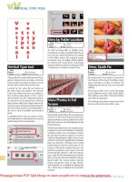
Figure 1 shows a generic view of a traditional main cable
deployment. A large cable runs from the CO to feed
different copper connection points. The fiber deployment
for a next generation network must also hit each copper
connection point. Therefore, it must logically follow the
same physical path—there are no other options.
Figure 1: A generic view of a traditional deployment of main
cables. These physical routes will be duplicated by fiber to
service these Nodes in an FTTN deployment.
A typical copper distribution duct system begins at
the CO with multiple ducts running out a specified
distance before some of the ducts branch out into other
directions. Therefore, it’s not one cable running in one
duct to one group of cabinets. Rather, it is multiple ducts
containing multiple cables that share the infrastructure
for part of the length and then branch in different
directions.
These radial feeds from the CO provide coverage to a
nominal circular area of between four and eight cabinets
per main cable. The reach from the CO is approximately
4-5 km, dictated by the cable gauge. Two or more main
cables might feed in the same direction, varying only in
overall length or reach. One main cable would feed the
closer cabinets while the other feeds the more distant
cabinets. For example, there might be 35,000 copper
pairs leaving a CO on 20 main cables of various sizes.
With those 20 cables, providers are able to feed 80 to
100 cabinets.
Converting to fiber
When converting the service area to FTTN, the same rule
applies in Europe as with other geographical areas—
loops have to be cut back to below 5000 feet.
For ADSL or VDSL services, distances must be within
1.5 km from the equipment to the customer. Since
existing CO areas are typically about 5 km, fiber feeds
would have to be built to service the outer two-thirds
of the customers. Basically, the CO would feed the closer
third of the customers, but the other two-thirds would
require conversion to active cabinets.
This raises several very practical issues for the network
planner. Two-thirds of the cabinets will need to be fiber
fed, meaning 60 cabinets must now be active. This will
have to be achieved using existing ducts that normally
travel in four different directions before branching out.
Therefore, each route would typically cover about 12-18
cabinets.
However, using the ducts is still more cost effective than
building rings. For example, a 5 km serving area with
four main routes would require about 20 km of fiber
cable. A ring serving the same area would require more
than 31 km of cable. A full ring would be cost prohibitive
in other ways as well, including the requirement for
extensive civil works. So the question remains—how can
you attain some sort of redundancy in a tree and branch
architecture?
Additionally, planners must decide how many fiber
drops per cabinet will provide enough bandwidth for
today’s needs as well as tomorrow’s passive optical
network (PON) upgrades. They should ensure there is
plenty of fiber, particularly since the fiber counts from
cable to cable don’t vary enormously in terms of price
points today. Choosing 24 fiber drops per cabinet, for
example, a provider could service six cabinets from a 144-
count cable, 12 cabinets from a 288-count cable, or 24
cabinets from a 576-count cable.
Using smaller feeder cables may provide some
advantages. For instance, winching a 576-count cable
through a congested duct is more difficult than pulling a
144-count cable through. Running smaller cables would
also provide an easier means to achieve redundancy, as
we’ll discover later in this paper.
400-2,400 Pair x “n”
Central Office
PCP
PCP
PCP
PCP
PCP
PCP
2,400 Pair
1,200 Pair
800 Pair
400 Pair
400 Pair
800 Pair
400 Pair
Practical considerations in the European market for building and future-proofing robust, flexible FTTN infrastructures
Page 3
Patch or splice?
Finally, there is the age-old consideration of whether to
splice or patch (connect) cables. Again, many service
providers have their own rules and standards. In a patch,
the cable is brought above ground into a patch cabinet.
The alternative is to splice it in an underground splice
closure. Since the mindset in Europe has always been
a simple building to building connection, every fiber
would be typically spliced to the exact same fiber in the
next section. But when the requirement is to provide
services to small groups of houses in a tree and branch
configuration, this is no longer practical for achieving
maximum flexibility.
In a distribution network that branches in several
directions, there are advantages in having patch cabinets,
at least in certain locations. Again, it’s incumbent upon
the planner to decide where advantage is gained from
connectorization in the network. These would be areas
that may require access by technicians for reconfiguration
or troubleshooting sections of the network over the next
25 years.
An all-spliced network could make operational costs
soar when technicians must gain access to a particular
part of the network. For example, getting access in a
water-filled manhole would require the additional cost of
rolling out a tanker truck to pump the water out to gain
access to the splice closure. A patch solution, or at least a
combination splice-patch solution, makes the technician’s
life much easier and can save operational expense.
A patch solution where it makes the most sense is the
first step in building a more flexible and robust FTTN
architecture. Even though existing ducts are being used,
planners should create, at a minimum, one main fiber
cross-connect (MFCC) at a suitable junction in the physical
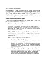
network. Figure 2 shows two high-pair-count cables
feeding back toward the CO. The cables are routed
through the same physical duct routes or duct nests.
The MFCC is the most convenient point to bring the
fiber above ground to create easier access and improve
network flexibility. Again, not every splice or cable should
be above the ground—just where it makes sense within
the physical infrastructure. A secondary fiber cross-
connect point (SFCC) is also shown in Figure 2 where the
second cable branches in several different directions.
Possible second fiber
cross-connect point
Central Office > 2 km
PCP
PCP
PCP
PCP
PCP
PCP
PCP
PCP
PCP
PCP
PCP
Create fiber
cross-connect point
Typical multiple
way duct route
Figure 2: Establishing fiber cross-connect points increases network flexibility and utilization, and reduces operational costs.
Achieving redundancy
Achieving redundancy in a tree and branch network systems can be done by first giving consideration
to cable size—for example, using two 144-count cables instead of a single 288-count cable. By bringing
the two 144-count cables above ground into a fiber cabinet, the tubes in each cable can be split out.
By putting 72 fibers of the first cable onto the second cable and vice versa, a second functional route is
formed downstream. Should a break occur in either feeder cable, a redundant path is now available.
Further redundancy can also occur farther downstream. In Figure 2, the one main feeder cable passing
through the MFFC continues to the SFCC. At this junction, the fiber tubes can be split once again to
create redundancy from that point downstream to each PCP. Using a 50/50 splitter at each cabinet
allows automatic route transfer in the event of a tube or complete cable failure.
Since only short distances are involved, loss budget issues associated with patching and splicing will be
minimal. The benefit is in achieving a degree of security through redundant cable routes from the CO to
the nodes.
There are still a few other issues to consider in planning an FTTN architecture through existing
underground ducts. For instance, planners should not focus on trying to squeeze more things into
smaller spaces. Despite space considerations, they should consider leaving room at each FTTN node for
adding splitter modules for future PON upgrades. They may even want to consider using a 90/10 splitter
to feed one fiber back to the CO to provide a test field. This would provide technicians the ability to test
and monitor every cabinet from a single point. Patch cabinets should also be allowed extra space for
future additions. These could possibly become hubs for future PON configurations.
ADC has always been a proponent of designing networks with the future in mind—making them as
flexible, accessible, and uncomplicated as possible, while giving ample consideration to potential issues
and challenges throughout the life of the network. Although there are capital expense implications
in addressing most of these issues, they must be weighed against the potential operational savings in
the future. Since each network is physically unique, planners must carefully consider the correct steps
to achieving maximum flexibility, easy access, and the most robust architecture possible to meet the
demands of tomorrow’s FTTN network.
Web Site: www.adc.com
From North America, Call Toll Free: 1-800-366-3891 • Outside of North America: +1-952-938-8080
Fax: +1-952-917-3237 • For a listing of ADC’s global sales office locations, please refer to our Web site.
ADC Telecommunications, Inc., P.O. Box 1101, Minneapolis, Minnesota USA 55440-1101
Specifications published here are current as of the date of publication of this document. Because we are continuously
improving our products, ADC reserves the right to change specifications without prior notice. At any time, you may
verify product specifications by contacting our headquarters office in Minneapolis. ADC Telecommunications, Inc.
views its patent portfolio as an important corporate asset and vigorously enforces its patents. Products or features
contained herein may be covered by one or more U.S. or foreign patents. An Equal Opportunity Employer
102473AE 5/06 Original © 2006 ADC Telecommunications, Inc. All Rights Reserved
WHITE PAPER