Tài liệu PBX Networking Standard Telephony pdf
Bạn đang xem bản rút gọn của tài liệu. Xem và tải ngay bản đầy đủ của tài liệu tại đây (1.05 MB, 41 trang )
Designing Voice over Data—PBX Integration with Data Networks Copyright © 1999, Cisco Systems, Inc. 2-1
© 2000, Cisco Systems, Inc.
www.cisco.com
Networking - 791-1
PBX NetworkingPBX Networking
PBX Networking
Standard Telephony
Standard Telephony
Designing Voice over Data—PBX Integration with Data Networks Copyright © 1999, Cisco Systems, Inc. 2-2
Networking - 791-2
Designing Voice over Data —PBX Integration with Data Networks
© 2000, Cisco Systems, Inc.
www.cisco.com
Module Objectives
Module Objectives
Upon completion of this chapter, you will be able to:
• Describe typical PBX network applications
• Identify the types of signaling used in PBX networks
• Define the proprietary PBX protocolsfrom Lucent & Nortel
• Identify design issuesrelated with integrating PBX traffic over
data networks for both Lucent and Nortel PBXs
Upon completion of this chapter, you will be able to:
• Describe typical PBX network applications
• Identify the types of signaling used in PBX networks
• Define the proprietary PBX protocols from Lucent & Nortel
• Identify design issues related with integrating PBX-traffic over data
networks for both Lucent and Nortel PBXs
Designing Voice over Data—PBX Integration with Data Networks Copyright © 1999, Cisco Systems, Inc. 2-3
Networking - 791-3
Designing Voice over Data —PBX Integration with Data Networks
© 2000, Cisco Systems, Inc.
www.cisco.com
Module Content
Module Content
I. PBX Review
II. PBX Signaling
A. Analog
B. Digital
III. General Design Implications
More specifically, this module focuses on a review of PBX.
Designing Voice over Data—PBX Integration with Data Networks Copyright © 1999, Cisco Systems, Inc. 2-4
Networking - 791-4
Designing Voice over Data —PBX Integration with Data Networks
© 2000, Cisco Systems, Inc.
www.cisco.com
PBX Benefits
PBX Benefits
• Allows many phones in an office to share fewer
number of “outside lines,” controlling cost growth
• Supports features
– Short-number extensions
– Conferencing
– Forwarding
– Security restrictions
– Lowest cost and other policy-based routing
– Manipulation of outgoing and incoming digits
– Park, etc.
• Provides for sophisticated selection of route, i.e.,
saves on toll costs
• Provides detailed use records
There are many benefits of PBX.
•It allows many phones in an office to share a fewer number of
outside lines, which helps to control cost growth.
•It supports many different features, including:
• Short-numbering extensions
• Conferencing
• Forwarding
• Security restrictions
• Lowest cost and other policy-based routing
• Manipulation of outgoing and incoming digits
• Park, etc.
•It provides for sophisticated selection of route, i.e., it saves on toll
costs
•It provides detailed use records
Designing Voice over Data—PBX Integration with Data Networks Copyright © 1999, Cisco Systems, Inc. 2-5
A private branch exchange (PBX) cabinet is a metal housing designed to
hold the electronic components that make the PBX work. Each cabinet
contains one or more shelves, or carriers with slots. Each shelf in the PBX
accepts a certain number of circuit boards. There are different types of
circuit boards within a PBX, including the following:
• Both-way trunk circuit boards—Supports both-way trunks or
combination trunks that receive incoming calls or place outgoing
calls.
• DID trunk circuit boards—Support a special type of trunk used for
incoming direct inward dialing (DID) calls only.
• Universal trunk circuit boards—Mix both-way trunks, DID trunks,
loop-start tie trunks on the same board. Also support Recorded
ANnouncement (RAN), overhead paging, and music-on-hold.
• ISDN circuit boards—Support lines connecting the PBX and another
device over an ISDN PRI or BRI. PRI and U-Interface BRI are point-
to-point. S/T-Interface BRI is point-to-multipoint.
Networking - 791-5
Designing Voice over Data —PBX Integration with Data Networks
© 2000, Cisco Systems, Inc.
www.cisco.com
Circuit Boards
Circuit Boards
Need slide on Circuit Boards
Need slide on Circuit Boards
Designing Voice over Data—PBX Integration with Data Networks Copyright © 1999, Cisco Systems, Inc. 2-6
Extra Text
• Tie trunk circuit boards—Support point-to-point lines connecting two PBXs
so that the users of both systems may communicate with each other
without per-minute toll charges. Most analog Ear and Mouth (E&M) tie-
trunk circuit boards handle two or four tie trunks.
• T1/E1 circuit boards—Multiplexers that support a high-capacity T1 or E1
circuit, enabling up to 24 (T1) or 30 (E1) voice conversations at one time.
Recall that T1 is the term used for a DS-1 signal carried over two copper
pairs. T1 is a type of line that is not a signaling type.
• Digital telephone circuit boards—Support digital telephones. The analog
voice signal converts to a digital form at the telephone and goes back to
the PBX as pulse code modulated (PCM) encoded bytes.
• Analog telephone circuit boards—Support analog telephones, as well as
fax machines, computer modems, and any other device which utilizes a
plain old telephone service (POTS)-type loop start analog interface.
• DTMF receiver circuit boards—Contain dual tone multifrequency (DTMF)
receivers.
• MF receiver circuit boards -Contain multifrequency (MF) receivers.
• Tone sender boards -Generate all the tones for a system, including dial
tone, busy tone, DTMF, MF, and CLASS.
• Common control circuit boards—Central processing unit of the PBX.
When two PBXs communicate over non-ISDN tie trunks, they can use E&M
signaling, among others.
Networking - 791-6
Designing Voice over Data —PBX Integration with Data Networks
© 2000, Cisco Systems, Inc.
www.cisco.com
Circuit Boards
Circuit Boards
Need slide on Circuit Boards
Need slide on Circuit Boards
Designing Voice over Data—PBX Integration with Data Networks Copyright © 1999, Cisco Systems, Inc. 2-7
Networking - 791-7
Designing Voice over Data —PBX Integration with Data Networks
© 2000, Cisco Systems, Inc.
www.cisco.com
Wide-Area PBX Networking
Wide-Area PBX Networking
• PBX trunking/transport
– Example of services for long-distance calls
10s
100s
10s
100s
Switch
CO CO
NYLA
CO Trunks
Tie Trunks
213–666–5678
212–345–2424
CO Trunks
Tie Trunks
PSTN
FX
416
526–1234
Switch
PSTN
IXC
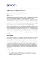
This graphic depicts typical legacy PBX-to-PBX connectivity connecting two
PBXs in different local access and transport areas (LATAs).
The actual connections are from the PBX to the local exchange carrier
(LEC), for example, the central office (CO) switch then to a LEC tandem
switch. From there the connection is made to an inter exchange carrier’s
(IXC) point-of-presence (POP), then into the IXC network cloud. The
connections at the other end follow the reverse path.
Tie-trunks are generally cross-connected (hard-wired) instead of switched at
the LEC (CO) and IXC level. If they are configured to go into a LEC/IXC
switch, they are configured as dedicated nailed-up circuits.
Designing Voice over Data—PBX Integration with Data Networks Copyright © 1999, Cisco Systems, Inc. 2-8
Networking - 791-8
Designing Voice over Data —PBX Integration with Data Networks
© 2000, Cisco Systems, Inc.
www.cisco.com
10s
100s
10s
100s
10s
100s
10s
100s
CO CO NYLA
CO Trunks
Tie Trunks
213–666–5678 212–345–2424
CO Trunks
Tie Trunks
QoS WAN
Internet/Intranet
FX
(212)
526–1234
Switch Switch
PSTN
PBX Connectivity over Data Network
PBX Connectivity over Data Network
Route Replacement
The graphic shows a generic but typical start of using a data network for
PBX-to-PBX connectivity. The enterprise still has its legacy connections.
Designing Voice over Data—PBX Integration with Data Networks Copyright © 1999, Cisco Systems, Inc. 2-9
Networking - 791-9
Designing Voice over Data —PBX Integration with Data Networks
© 2000, Cisco Systems, Inc.
www.cisco.com
The PBX “Stack”
The PBX “Stack”
PBX Line Service Types
PBX Signaling
PBX Services
PBX Supported
Applications
Hold
Forward
Park
Conference
Building Page
Networking
Local Extensions
CCS,CAS, QSIG, Digital (PBX-to-PBX)
E&M, Proprietary Digital (PBX-phone)
Tie trunks
CO trunks
DID trunks
FX trunks
RAN trunks
Subscriber lines
Analog/Digital
IVR
ACD
Voice Mail
Msg on Hold
Call Center
Loop-type analog,
T1,E1,n-wire,
PRI, BRI
Physical Line Type
The PBX stack is a representation of the various layers of functionality
supported by a PBX. The lists of items for each layer are illustrative and not
complete.
You may also think about other components that provide line and trunk
supervision and signaling methods:.
For analog and channel associated signaling (CAS):
• Seizure and disconnect supervision: loop-start, ground start, E&M, loop
dial repeating
• (Dial) starting arrangements: Wink-start, immediate dial, delay dial
• Addressing methods: DTMF, MF, dial pulse
• Answer supervision: Battery reversal, E&M control lead signaling
For ISDN:
• Access line type: BRI (DSL), PRI (T1 or E1)
• Line protocol: For BRI: U (2B1Q) or S/T (pseudo-ternary); for PRI: DS1
or E1
• D channel protocol: NI-2, QSIG, DMS custom, AT&T custom, Nortel
MCDN custom
Designing Voice over Data—PBX Integration with Data Networks Copyright © 1999, Cisco Systems, Inc. 2-10
Networking - 791-10
Designing Voice over Data —PBX Integration with Data Networks
© 2000, Cisco Systems, Inc.
www.cisco.com
PBX Circuit Types
PBX Circuit Types
SwitchSwitch
SwitchSwitch
Central Office
Central
Office (CO)
“FX”
Tie Lines
Analog 2/4 wire
type 1-5
Digital
2/4 wire
Analog
2 wire
2 wire
E&M, 2/4 wire
5 types
“FX”
Analog 2/4 wire
type 1-5
1
3
4
5
6
T1 tie line
FXO
interface
FXO
interface
2
Analog
Analog trunk circuits connect automated systems (such as a PBX) and the network
(such as a central office). The most common form of analog tie trunk is the E&M
interface. Like a serial port, E&M has a DTE/DCE type of reference. In the telecom
world, the “trunking” side is similar to the DCE, and is usually associated with CO
functionality. The Cisco 3600 acts as this side of the interface.
The other side is referred to as the “signaling” side, like a DTE, and is usually a
device such as a PBX. There are five distinct physical configurations for the E&M
interface (types 1-5), and two distinct flavors of audio interface (2-wire or 4-wire).
Note that even though it may be called a 4-wire E&M circuit, it is likely to have 6 to 8
physical wires! The difference between a 2-wire and 4-wire circuit is whether the
audio path is full duplex on one pair or two pairs of wires.
The foreign exchange office (FXO) interface (typically an interface card) supports
the CO side loop-start line. The foreign exchange station (FXS) supports the
station-side of the loop-start line. Foreign exchange (FX) is the term used
historically to describe the PBX or telephone instrument connection to a remote CO.
Typically the “FX line” was used to get local, toll-free dialing in another LATA.
Digital
Digital T1/E1trunk circuits are 4 wire. In Europe, and soon in North America, ISDN
BRI can be used as a trunk. The BRI U-interface is 2-wire. Subscriber lines may be
2- or 4-wire. They support several typical analog signaling protocols, both in-band
and out-of-band, ISDN, and analog emulation.
Designing Voice over Data—PBX Integration with Data Networks Copyright © 1999, Cisco Systems, Inc. 2-11
Networking - 791-11
Designing Voice over Data —PBX Integration with Data Networks
© 2000, Cisco Systems, Inc.
www.cisco.com
Module Content
Module Content
I. PBX Review
II. PBX Signaling
A. Analog
B. Digital
III. General Design Implications
The next section of this presentation is going to discuss PBX signaling.
Designing Voice over Data—PBX Integration with Data Networks Copyright © 1999, Cisco Systems, Inc. 2-12
Networking - 791-12
Designing Voice over Data —PBX Integration with Data Networks
© 2000, Cisco Systems, Inc.
www.cisco.com
• 2-wire
• Loop start
• Ground start
Analog
• E&M
• 2-wire, 4-wire
• Five types I-V
• (Cisco I,II,III,V)
Digital
• CAS—Channel
associated signaling
• In-band signaling
• CCS—Common
channel signaling
• Out-of-band signaling
• Digital subscriber
lines: 2-wire, 4-wire
• Digital trunks: 4-wire
Method of communicating telephony events: off-hook, busy, on-hook, etc.
Types of Signaling
Types of Signaling
There are two flavors of loop start lines. The Station side loop start line uses
an FXS interface, while the CO side uses an FXO interface.Typically, digital
lines are associated with out-of-band signaling.
Designing Voice over Data—PBX Integration with Data Networks Copyright © 1999, Cisco Systems, Inc. 2-13
Networking - 791-13
Designing Voice over Data —PBX Integration with Data Networks
© 2000, Cisco Systems, Inc.
www.cisco.com
Types of Telephony Signaling
Types of Telephony Signaling
• Supervisory
– Call setup, call teardown, Flash
(for example, 3-way calling)
– Two states: on-hook and off-hook (see note)
• Addressing
– Signal numbers that make up phone address
• Call progress
– Denotes progress of call (e.g., dial tone, alerting
[ringback], busy, network busy, error)
Types of telephony signaling are as follows:
• Supervisory—Monitoring the status of a line or circuit to determine if it
is busy, idle or requesting service (flash-hook). Supervision is the term
derived from the function of monitoring manual circuits on a
switchboard. At that time, the signal was conveyed by a switchboard
lamp for the line. Now voltage levels, signaling tones, or bits (digital
signaling) provide this function.
• Addressing—The process of transmitting routing and destination
signals over the network. Addressing signals include dial pulses, tone
pulses, or data pulses over loops, trunks, and signaling networks.
• Call progress—Signals that inform the user of the status of the call
setup, for example, busy tones.
Designing Voice over Data—PBX Integration with Data Networks Copyright © 1999, Cisco Systems, Inc. 2-14
Networking - 791-14
Designing Voice over Data —PBX Integration with Data Networks
© 2000, Cisco Systems, Inc.
www.cisco.com
Module Content
Module Content
I. PBX Review
II. PBX Signaling
A. Analog
B. Digital
III. General Design Implications
The next few slides will focus on the analog side of PBX Signaling.
Designing Voice over Data—PBX Integration with Data Networks Copyright © 1999, Cisco Systems, Inc. 2-15
Networking - 791-15
Designing Voice over Data —PBX Integration with Data Networks
© 2000, Cisco Systems, Inc.
www.cisco.com
• Loop start signaling station side
– FXS Interface Side
• Loop start signaling CO side
– FXO interface side
• Ground start CO side
• E&M—Used for PBX dial tie trunks or carrier systems
– The best way to connect switches together using analog facilities
E&M Trunk
Station
Side Loop
Start Line
PBX or
CO Switch
CO Side Loop
Start Line
PBX
Station
Side Loop
Start Line
Station Loop
Signaling
PBX-to-PBX Signaling, or
PBX to CO Signaling
Analog Signaling
Analog Signaling
There are three traditional types of analog signaling: E&M, station side
loop-start Signaling (FXO interface side), and CO side loop-start
signaling. Stations connected to PBXs or central offices use the FXS
interface, while CO switches use the FXO interface.
Consider the various interfaces available from the PBX when
interconnecting Cisco components. Understand that the connection
needs to be supervised. Supervision handles such things as call setup
and teardown, and monitors the actions of the connected entities.
Analog is not the best approach for more than a few trunks. The best way
today is connecting PBXs via an ISDN PRI over a T1 circuit. The
signaling used must support call supervision. Without supervision, if a
caller hangs up the phone after receiving no answer, the “called” remote
phone will continue to ring.
The following diagram reviews the FXS interface and FXO interface
connections.
Designing Voice over Data—PBX Integration with Data Networks Copyright © 1999, Cisco Systems, Inc. 2-16
Networking - 791 -16
Designing Voice over Data—PBX Integration with Data Networks © 2000, Cisco Systems, Inc.www.cisco.com
State E-Lead M-Lead
On-hook Open Ground
Off-hook Ground Battery Voltage
E&M Trunk Group
PBX PBX
E
EM
M
Analog Signaling: E&M Analog Signaling: E&M
• E&M signaling (PBXs, switches)
– Separate signaling leads for
each direction
– 6 to 8 physical wires
– E ("Ear" or "Earth")—Signal wire
from trunking (CO) side to
signaling (user) side.
– M ("Mouth" or "Magnet")—Signal
wire from signaling (user) side to
trunking (CO) side
– Allows independent signaling
Analog
Analog trunk circuits connect automated systems (such as a PBX) and the network
(such as a central office, or CO). The most common form of analog tie trunk is the
E&M interface. Like a serial port, E&M has a DTE/DCE type of reference. In the
telecom world, the “trunking” side is similar to the DCE, and is usually associated with
CO functionality. The Cisco 3600 acts as this side of the interface.
The other side is referred to as the “signaling” side, like a DTE, and is usually a device
such as a PBX. There are five distinct physical configurations for the signaling part of
the interface (types 1 to 5), and two distinct flavors of audio interface (2-wire or 4-
wire). Note that even though it may be called a 4-wire E&M circuit, it is likely to have 6
to 8 physical wires! The difference between a 2-wire and 4-wire circuit is whether the
audio path is full-duplex on one or two pairs of wires.
The five E&M types are as follows:
• Type 1
• Asymmetrical: Cannot be used “back to back”
• Does not provide ground isolation between equipment, may produce noise
in audio circuits, or be susceptible to electrical transients
• Only requires six wires
• Most common interface in North America
Designing Voice over Data—PBX Integration with Data Networks Copyright © 1999, Cisco Systems, Inc. 2-17
• Type 2
• Can be used “back to back” for either trunking or signaling sides with
crossover cable
• Provides complete ground isolation
• Requires all eight wires
• Usually used on Centrex lines and Nortel PBX systems
• Type 3
• Asymmetrical: Cannot be used “ back to back”
• Provides ground isolation
• Requires all eight wires
• Mostly used on older, step-by-step CO systems
• Type 4
• Can be used “back-to-back” with crossover cable
• Does not provide ground isolation
• Requires all eight wires
• Most difficult to debug
Designing Voice over Data—PBX Integration with Data Networks Copyright © 1999, Cisco Systems, Inc. 2-18
Networking - 791-18
Designing Voice over Data —PBX Integration with Data Networks
© 2000, Cisco Systems, Inc.
www.cisco.com
State E-Lead M-Lead
On-hook Open Ground
Off-hook Ground Battery Voltage
E&M Trunk Group
PBX PBX
E
EM
M
Analog Signaling: E&M (continued)
Analog Signaling: E&M (continued)
• E&M signaling (PBXs, switches)
– Separate signaling leads for
each direction
– 6 to 8 physical wires
– E ("Ear" or "Earth")—Signal wire
from trunking (CO) side to
signaling (user) side.
– M ("Mouth" or "Magnet")—Signal
wire from signaling (user) side to
trunking (CO) side
– Allows independent signaling
• Type 5
• Can be used “back-to-back” with crossover cable
• Does not provide ground isolation
• Only requires six wires
• Simplest to debug
• Used on some AT&T and Lucent PBX systems and widely used outside
North America
In the voice telephony world, the terms “lines” and “trunks” have special meaning.
A trunk is a circuit which connects two pieces of a switching environment together.
A trunk, DIDs excepted, is not assigned a publicly dialable directory number. A line
is a circuit that connects a piece of the switching environment to a subscriber. A line
always has a directory number assigned to it.
When a subscriber places a call to another subscriber on the same switch, the call
is a “line-to-line” call. When a subscriber places a call to a subscriber on another
switch, it is a “line-to-trunk” to “trunk-to-line” call.
The terms line and trunk are sometimes in the eye of the beholder. Circuits that
PBXs use to connect to a CO switch and to place or receive calls are viewed by the
PBX as “trunks." The same circuits may be considered, however, as “lines” to the
CO switch. The same CO POTS circuit which has been assigned a directory
number (for example, 573-555-1212) can be used equally well by a residential
subscriber with a single line phone as it can by a PBX. The circuit is connected on
the CO’s line side, and on the PBX’s trunk side. To the CO, the circuit is a line. To
the PBX, the circuit is a trunk.
Designing Voice over Data—PBX Integration with Data Networks Copyright © 1999, Cisco Systems, Inc. 2-19
Networking - 791 -19
Designing Voice over Data—PBX Integration with Data Networks © 2000, Cisco Systems, Inc.www.cisco.com
State E-Lead M-Lead
On-hook Open Ground
Off-hook Ground Battery Voltage
E&M Trunk Group
PBX PBX
E
EM
M
Analog Signaling: E&M (continued)Analog Signaling: E&M (continued)
• E&M signaling (PBXs, switches)
– Separate signaling leads for
each direction
– 6 to 8 physical wires
– E ("Ear" or "Earth")—Signal wire
from trunking (CO) side to
signaling (user) side.
– M ("Mouth" or "Magnet")—Signal
wire from signaling (user) side to
trunking (CO) side
– Allows independent signaling
Analog Supervisory Signaling
It is possible to mix starting signaling protocols, but is is not recommended. The
following are three such signaling protocols:
• Immediate start signaling
• The originating switch goes off-hook, waits for a finite period of time (200
ms, for example), then sends the dial digits without regard to the far end.
• An immediate start interface can usually originate a call to a wink start
interface.
• An immediate start interface can usually place a call to a delaydial
interface if the delay pulse is shorter than the immediate start delay.
Otherwise, operation is erratic.
Designing Voice over Data—PBX Integration with Data Networks Copyright © 1999, Cisco Systems, Inc. 2-20
• wink start signaling
– The originating switch goes off-hook, waits for a temporary off-hook pulse
from the other end (which is interpreted as an indication to proceed), then
sends the dial digits. wink start was developed to minimize glare, where
both ends attempt to seize the trunk at the same time.
– A wink start interface can usually originate a call into a delaydial interface
if there is a delay pulse. Otherwise, the call will hang, with a 50 percent
chance of working or not.
• Delay dial signaling
– The originating side goes off-hook and waits for about 200 ms, then
checks to see if the far end is on-hook. If the far end is on-hook, it outputs
dial digits. If the far end is off-hook, it waits until it goes on-hook, then
outputs dial digits.
– This protocol was invented for use with systems that have fewer digit
collectors than trunk interfaces. The delay signal says, in effect “Wait—
I'm not ready to receive digits.”
– A delay dial interface can, for the most part, originate a call into an
immediate start or wink start interface.
Addressing via “in-band” signaling is performed by dial pulse, DTMF, and MF.
These can be used over digital, for example, T1 circuits. Dial pulse is emulated with
A/B bits, while DTMF is carried as PCM-encoded audio.
Networking - 791-20
Designing Voice over Data —PBX Integration with Data Networks
© 2000, Cisco Systems, Inc.
www.cisco.com
State E-Lead M-Lead
On-hook Open Ground
Off-hook Ground Battery Voltage
E&M Trunk Group
PBX PBX
E
EM
M
Analog Signaling: E&M (continued)
Analog Signaling: E&M (continued)
• E&M signaling (PBXs, switches)
– Separate signaling leads for
each direction
– 6 to 8 physical wires
– E ("Ear" or "Earth")—Signal wire
from trunking (CO) side to
signaling (user) side.
– M ("Mouth" or "Magnet")—Signal
wire from signaling (user) side to
trunking (CO) side
– Allows independent signaling
Designing Voice over Data—PBX Integration with Data Networks Copyright © 1999, Cisco Systems, Inc. 2-21
Networking - 791-21
Designing Voice over Data —PBX Integration with Data Networks © 2000, Cisco Systems, Inc.www.cisco.com
Addressing
Addressing
• Calling party sends digits representing station called
(possibly along with routing directions)
• Three primary methods of sending addressing
information through analog trunks:
– Dial pulse (“rotary”)
– DTMF (“touch tone”)*
– MF
• Addressing digits are sent according to dial plan
*Touch Tone is an ATT SM; Nortel calls theirs Digitone
For any telephone network to function, each telephone must be identified by a unique
address. Voice addressing relies on a combination of international and national
standards, local telephone company practices and internal customer-specific codes.
The International Telecommunications Union (ITU-T) recommendation E.164 defines
the international numbering plan for ISDN. The international telephone service
numbering plan is a subset of this numbering plan. Each country's national numbering
plan must conform to the E.164 recommendation and work in conjunction with the
international numbering plan. Providers of public switched telephone service must
ensure that their numbering plan aligns with the E164 recommendation and that each
of their customers' networks conform.
Alternate numbering schemes are employed by users and Public Switched Telephone
Network (PSTN) providers for specific reasons. Exceptions to the E.164
recommendation include Carrier Identification Code (CIC), a prefix to select different
long-distance carriers; prefixes to select tie lines, trunk groups, and WATS lines; and
private number plans, such as three- to seven-digit dialing. When integrating voice
and data networks, each of these numbering plans will need to be considered.
Answer Supervision
Answer supervision indicates that the called party has answered the phone. Answer
supervision may take several forms depending on the type of trunk , and so on as
follows:
• Loop closure toward the terminating CO from a loop-start POTS phone set going
offhook
• Battery reversal for loop-type trunk circuits
• Sustained off-hook from the terminating end for general CO-type trunk circuits
Designing Voice over Data—PBX Integration with Data Networks Copyright © 1999, Cisco Systems, Inc. 2-22
For non-PBX loop start lines, the CO does not provide answer supervision to the
originating end. For loop or ground start lines terminating on PBXs, the CO may
provide battery reversal answer supervision if the customer requests it.
DTMF is most commonly used for PBX connections. MF can be used between the
PBX and a CO for Feature-Group D trunks (in which case the PBX appears to the CO
as an IXC switch) or for Centralized Automatic Message Accounting (CAMA) trunks.
CAMA trunks used to be widely used in the CO environment (and PBX hotel/motel
environment) for customer billing. Today, their use is mostly limited to 911
connectivity, where it is frequently a requirement over ISDN.
Networking - 791-22
Designing Voice over Data —PBX Integration with Data Networks
© 2000, Cisco Systems, Inc.
www.cisco.com
Addressing (continued)
Addressing (continued)
• Calling party sends digits representing station called
(possibly along with routing directions)
• Three primary methods of sending addressing
information through analog trunks:
– Dial pulse (“rotary”)
– DTMF (“touch tone”)*
– MF
• Addressing digits are sent according to dial plan
*Touch Tone is an ATT SM; Nortel calls theirs Digitone
Designing Voice over Data—PBX Integration with Data Networks Copyright © 1999, Cisco Systems, Inc. 2-23
Networking - 791-23
Designing Voice over Data —PBX Integration with Data Networks
© 2000, Cisco Systems, Inc.
www.cisco.com
Module Content
Module Content
I. PBX Review
II. PBX Signaling
A. Analog
B. Digital
III. General Design Implications
The next section of this presentation is going to discuss the digital side of PBX
Signaling. There are both legacy standards-based signaling approaches and
internationally standardized approaches.
Designing Voice over Data—PBX Integration with Data Networks Copyright © 1999, Cisco Systems, Inc. 2-24
Networking - 791-24
Designing Voice over Data —PBX Integration with Data Networks
© 2000, Cisco Systems, Inc.
www.cisco.com
Digital Trunk Signaling
Digital Trunk Signaling
• Trunk (circuit) signaling
– PBX-to-CO signaling
– PBX-to-PBX tie trunk signaling
• Digital signaling protocols
– Channel associated signaling (CAS)
– Common channel signaling (CCS)
• ISDN
– QSIG
There is a clear relationship between the user and the network.
A central office trunk (COT) is a “both-way” trunk that generally can be used to
place outgoing calls from the PBX to the PSTN. Incoming calls are generally sent to
the operator console or a predefined station. This is called Direct In-Line (DIL), or
private lines or “auto-terminate."
This differs from DID, which we will talk about in a minute, in that incoming calls to
the PBX are terminated at a predefined location.
In a PBX environment, ground start is the preferred signaling type for both-way
trunks. Ground start prevents a condition known as “glare,” or “collision” or “head-
on.” This is where an incoming call arrives on a trunk at the same time the PBX is
selecting the trunk for an outgoing call.
There are two primary digital signaling protocols: channel associated signaling
(CAS) and common channel signaling (CCS). ISDN is a method of common
channel signaling. Q Signaling (QSIG) (also written as q dot sig) is a internationally
standardized implementation of ISDN that emphasizes feature functionality between
different brands of PBXs. We will be covering these in depth later in this chapter.
Nortel calls CAS the digital trunk interface (DTI).
Designing Voice over Data—PBX Integration with Data Networks Copyright © 1999, Cisco Systems, Inc. 2-25
Networking - 791-25
Designing Voice over Data —PBX Integration with Data Networks
© 2000, Cisco Systems, Inc.
www.cisco.com
Digital Trunk Signaling:
PBX-to-CO & PBX-to-PBX
• T1/E1 CAS/CCS
• PRI D channel
• Proprietary protocols (PBX -to-PBX)
• DASS#2 (time slot 16 of E1)
Digital
PSTN
PBX
Private
network
SwitchSwitch SwitchSwitch
CO
CO
This graphic is an overview of PBX-to-CO and PBX-to-PBX legacy connectivity.
Typically, the connection is a T1 in North America, Japan, Taiwan, and South Korea;
or an E1 in Europe and the rest of the world.
DASS#2 , also know as ISDN 30-DASS#2 and ADS 2, is BT’s primary rate offering
which does not conform to European standard I.421. ISDN 30 is the equivalent of up
to 30 exchange lines (known as channels) delivered to the customers premises and
connected to an Integrated Services Private Branch Exchange (ISPBX) or for data
applications to a PC or multiplexer. It is available from only eight channels upward
and is therefore applicable to all industry sectors. ISDN 30 is provided normally over
fiber cable, but can be provided over transverse screen, microwave, or copper
twisted pairs. Each system is a 2-Mbps digital connection from the telephone
exchange presented as an RJ-45 connector.