Tài liệu Fundamentals of Ethernet Technology ppt
Bạn đang xem bản rút gọn của tài liệu. Xem và tải ngay bản đầy đủ của tài liệu tại đây (550.88 KB, 8 trang )
WHITE PAPER
Fundamentals of
Ethernet Technology
Fundamentals of
Ethernet Technology
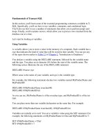
This white paper provides a brief tutorial on Ethernet – a family of standards that
defines several well-established 10 Mbps networking technologies and three
newer, high-speed offerings, Fast Ethernet, Gigabit Ethernet, and 10 Gigabit
Ethernet. It is intended for carrier network professionals, experts in the circuit-
switched technologies employed in public switched telephone networks (PSTN)
but often new to Ethernet and data networking.
Why Study Ethernet?
Ethernet is becoming an important carrier network technology. For many years,
it was relegated to office LANs (local area network), connecting PCs, servers, and
printers. Recent high-speed implementations, however, make Ethernet a viable
candidate to provide new carrier-based services such as:
• Voice over IP (VoIP), a technology that enables voice calls over data networks.
This may one day eliminate the need for separate voice and data facilities.
• Metropolitan area networks (MANs), high-bandwidth pipes that can link
company data centers over a 15 to 20 mile area
• Ethernet in the First Mile (EFM), an emerging standard that may compete with
DSL and cable modems to bring voice, video, and data to homes
The PSTN and Ethernet
The PSTN and Ethernet were designed for very different purposes. The result
is different technologies, at least in two key areas: switching techniques and
network access methods.
Circuit-Switching: A Voice-Friendly Technology
Have you ever heard a television news anchor question a
distant reporter over a satellite link? You probably have,
and it’s quite likely that the moments of dead air between
the question and the response made you uncomfortable.
That’s what latency does to conversation. Designers of the
public telephone network understood this, so they created
circuit-switched networks to minimize it. In these networks,
an end-to-end circuit is established (Figure 1) before a
conversation begins, and circuit resources aren’t relinquished
until someone hangs up. The bandwidth allocation, though
modest, is guaranteed.
Figure 1. Circuit-Switched Network
Page 3
New Requirements
Circuit switching worked quite well when most network traffic was voice. As data became a bigger part of the traffic
mix, however, it became less attractive. For data, latency isn’t as important as sufficient bandwidth to support brief,
but often large transmission bursts. As you can see from the following table, voice and data traffic have very different
transport requirements.
Traffic Bandwidth Required Burst Support Latency
Voice Small amount of reserved bandwidth Not Required Must be low
Data Variable bandwidth needs Extremely Important Not Important
Fundamentals of Ethernet Technology
DCE
Packet
A
Packet
B
DCE
Figure 2. Packet-Switched Network
Packet-Switching: A Data-Friendly Technology
Differing requirements drove the development of a
new data-friendly type of network, one that employed
a technology called packet-switching. Packet-switched
networks, including Ethernet, don’t bother to set up
an end-to-end circuit. Instead, the sender simply gains
access to the network and begins transmitting. Data is
divided into small independent units called packets that
are multiplexed onto high-capacity network connections.
Each packet is routed separately—based on addressing
information contained in the packet—and each packet
may take a different route to the destination (Figure 2).
A drawback to this “connectionless” service is that the
network cannot guarantee delivery. Network resources
are not reserved prior to transmission. Packets may be
lost because intermediate resources are busy or not
functioning. They may arrive out of order. The destination
system may not be on or connected to the network.
Though this method may sound awfully risky, service is
usually quite reliable. Mechanisms within the network
enable routing around busy or failed resources, and end
system software is designed to reassemble out-of-order
packets and to detect and recover from errors.
Switching Methods: An Analogy
Trains and cars provide a good analogy for how circuit switching and packet switching differ. Trains use the circuit-
switched model. The track is reserved for the entire length of the trip, each car on the train takes the same route to the
destination, and the engineer can’t decide to take a different route. Cars use the packet-switched model. Each driver
makes independent decisions about the best way to get to the destination. If a traffic jam is encountered, the driver
will switch lanes or even get off the freeway and take an alternate route. Cars going to the same destination may use
different routes to get there.
Fundamentals of Ethernet Technology
Page 4
Access Method Figure Description
Centralized
Access
Master Slave A
Your turn A
Slave B
Centralized access is characterized by a single
point of control. The controlling station
determines when each station can use the
medium to transmit data. Typically, this
involves some type of polling. A slave station
can transmit only when it is polled by the
master station.
Deterministic
Access
Token
Ring
Token
Deterministic access means stations transmit
in turn. In a token ring network, for example,
an electronic token is passed around the
ring, from station to station. Transmission is
permitted only when a station controls the
token.
Contention
Transmit Transmit
Collision
On a network that uses contention, any
station can transmit at any time, which is
a problem if two or more stations transmit
simultaneously. See the following section
for information on how CSMA/CD, the
contention method used on Ethernet
networks, manages channel access.
Shared Access on the PSTN: TDM
Though resources are guaranteed on the PSTN, exclusive
use of the cable from the originating phone to the
destination phone is prohibitively expensive. To provide
guaranteed bandwidth and still provide a means for
sharing the communication channel, time division
multiplexing (TDM) – the T-carrier system – has been
employed on the PSTN since the 1960s. With this system,
each phone conversation is given exclusive use of the
channel for a very short period. Samples of the speaker’s
voice are taken repeatedly, encoded into digital format,
and transmitted to the receiving telephone during
the time slice allocated for the call. The guaranteed
bandwidth (64 Kbps) is sufficient to give the telephone
users the illusion of exclusive use of resources.
Shared Access on an Ethernet LAN:
The Alternatives
Like the PSTN, Ethernet – originally designed for a shared
bus network – required some method for allocating use
of the communication channel among multiple network
stations. As discussed earlier, guaranteed bandwidth
isn’t important for data transport, so TDM wasn’t a
serious alternative. The data networking world provided
other alternatives, however, which can be divided
into three types or classes: centralized, deterministic,
and contention. The method the Ethernet designers
developed, CSMA/CD, follows the contention model.
Fundamentals of Ethernet Technology
Page 5
CSMA/CD
With CSMA/CD (Carrier Sense, Multiple Access/Collision Detection), a station that wants to transmit first “listens” to the
medium to determine whether another station is currently transmitting. If the medium is quiet, the station transmits. If
two stations accidentally transmit simultaneously, they each detect the collision and stop transmitting. Each then waits for
a random period before attempting to transmit again.
Ethernet Development
When first developed by Xerox Corporation, Ethernet was a proprietary LAN technology that operated on a shared
coaxial bus and was used exclusively for data. At its heart was the CSMA/CD access method. Since then, extraordinary
innovation has made a hash of these categories. The technology, for one thing, is no longer proprietary. The IEEE
standardized it in 1983 as IEEE 802.3, a document that has been updated more than a dozen times to include
improvements to the technology. These include:
• New types of cables: While coaxial is still an option, newer installations use less expensive unshielded twisted pair or
higher capacity fiber.
• New topologies: Cabling for the newer Ethernet standards uses a star, a bus-star hybrid called a tree, and even a ring.
• Increased bandwidth: The standards now define speeds between 1 Mbps and 1 Gbps (soon 10 Gbps).
• Support for full-duplex operation: The original standard supported half-duplex only. (On full-duplex networks, CSMA/
CD is not required.)
• Expansion of the distances supported: Ethernet is no longer restricted to the LAN. It is now deployed in MAN
networks, and will soon provide the underlying service in WAN (wide area network) environments as well.
• Support for new applications: Gigabit and 10 Gigabit Ethernet are able to provide transport for voice and video as well
as data.
Ethernet Advantages
Over the years, Ethernet has gained wide acceptance because it offers clear advantages over competing technologies.
Ethernet is:
• Easy to understand, implement, manage, and maintain
• Standards-based, largely guaranteeing communication with other compliant devices
• Relatively inexpensive. Many Ethernet devices have become commodities, and many systems are connected with
inexpensive twisted-pair cables.
• Highly flexible. Ethernet supports multiple topologies and types of cabling. New high-speed offerings support not only
data, but voice and video as well.
• Highly reliable. It’s a well-tested technology.
Fundamentals of Ethernet Technology
Page 6
Ethernet Standardization
Current Standards
Standardization is a key to the wide acceptance of Ethernet. The original standard, IEEE 802.3, was finalized in 1983. It
has been updated repeatedly since then. The scope of this paper doesn’t permit a discussion on each supplement, but a
brief description of the most important ones follows. If you want more information, the complete standard is available
from the IEEE (www.ieee802.org/3/).
Name Speed Max Line Length Medium Duplexing
802.3i
10BASE-T 10 Mbps 100 meters UTP, Category 3+ Half- and full-duplex
802.3u 100BASE-TX
100 Mbps 100 meters UTP, Category 5+ Half- and full-duplex
100BASE-FX 100 Mbps 2 kilometers Multimode fiber Half- and full-duplex
802.3z
1000BASE-LX 1 Gbps 5 kilometers Singlemode fiber Full-duplex
1000BASE-SX 1 Gbps 220 - 550 meters Multimode fiber Full-duplex
1000BASE-T 1 Gbps 100 meters UTP, Category 5+ Full-duplex
Emerging Standards
The IEEE 802.3 committee has two groups working on other standards that you may find interesting:
• The 10 Gb/s Ethernet Task Force is working on a standard for 10 Gigabit Ethernet (802.3ae). For more information, see
the group’s web site at grouper.ieee.org/groups/802/3/ae/.
• The Ethernet in the First Mile Working Group (802.3ah) is preparing a standard addressing Ethernet to the home. For
more information, see the group’s web site at www.ieee802.org/3/efm/.
Relationship to the OSI 7-Layer Model
Data networking professionals often categorize network services according to the OSI 7-Layer Reference Model, which is
also sometimes called the ISO 7-Layer Reference Model. An in-depth discussion of this subject is beyond the scope of this
white paper. For those who are curious, Ethernet fits into Layer 1 and Layer 2 of this model. For more information, there
are many good books on the subject, and shorter discussions can be found on many Internet web sites.
Ethernet Topology
Linear Bus
The original Ethernet standard specified a linear
bus (Figure 3). This topology is seldom used in new
installations. A cable break on a linear bus brings down
the whole network, and cabling costs can be reduced by
using twisted pair cables in a star configuration.
Star
The star topology is the most common (Figure 4).
It mitigates Ethernet distance limitations, can use
inexpensive unshielded twisted pair cables, and the
entire network doesn’t go down if a cable breaks or is
disconnected.
Nodes
File Server
Hub or Switch
Nodes
Figure 3. Linear Bus Topology
Figure 4. Star Topology
Fundamentals of Ethernet Technology
Page 7
Ethernet Devices
A number of devices populate an Ethernet network.
Network Interface Cards
Network interface cards, often called NICs, connect PCs
to the Ethernet network, providing physical connection
between the networking cable and the computer’s
internal bus. Cards are available for all Ethernet
standards. NICs are often 10/100 Mbps capable and will
automatically adjust to the speed used on the network.
Many NICs support both half- and full-duplex operation.
Repeaters and Hubs
Hubs are repeaters that connect two or more Ethernet
segments by regenerating the electrical signal and
broadcasting it out all ports. This means that every
connected segment is in the same collision domain.
In other words, when one device is transmitting, no
other device can transmit, or collisions will occur. This
is in contrast to Ethernet bridges and switches, which
are more discriminating about where they send the
transmission.
Ring
The ring (Figure 6) is used in Metropolitan Area Networks to deliver Ethernet using Add/Drop Multiplexers (ADMs) at
customer sites. The ADMs connect to the LAN router to deliver Ethernet.
ADM
Central
Office
LAN
ADM
ADM
ADM
ADM
Figure 5. Ring Topology
Figure 6. Ethernet Hub
Router
10/100 Switch
100 Mbps
10/100 Mbps
Full-Duplex
10/100 Switch
WAN
Bridges
Like repeaters, bridges straddle two Ethernet segments. Unlike repeaters, they make intelligent decisions
about which frames to forward and which to discard. Bridges reduce LAN traffic by dividing it into two
segments. They perform a service similar to switches, though most often bridges support one network
boundary only; switches support four or more segments.
Switches
Though they are multi-port devices like hubs, switches (Figure 7) are multiport bridges. Rather than
broadcasting a frame out every port as hubs do, they forward the frame to its intended destination only.
This means that each port becomes a separate collision domain. Bandwidth is shared only with stations
using that port. Ports that host only a single station can be configured for full-duplex communication,
which means collisions can’t occur. This arrangement also means that bandwidth doubles:
• A 10 Mbps connection provides 10 Mbps in each direction.
• A 100 Mbps link, provides 100 Mbps in each
Web Site: www.adc.com
From North America, Call Toll Free: 1-800-366-3891 • Outside of North America: +1-952-938-8080
Fax: +1-952-917-3237 • For a listing of ADC’s global sales office locations, please refer to our web site.
ADC Telecommunications, Inc., P.O. Box 1101, Minneapolis, Minnesota USA 55440-1101
Specifications published here are current as of the date of publication of this document. Because we are continuously
improving our products, ADC reserves the right to change specifications without prior notice. At any time, you may
verify product specifications by contacting our headquarters office in Minneapolis. ADC Telecommunications, Inc.
views its patent portfolio as an important corporate asset and vigorously enforces its patents. Products orfeatures
contained herein may be covered by one or more U.S. or foreign patents. An Equal Opportunity Employer
101821AE 12/05 Original © 2004, 2005 ADC Telecommunications, Inc. All Rights Reserved
WHITE PAPER
Routers
The task of defining a Local Area Network (LAN) domain is accomplished using a router. Routers
are located at the service provider’s central office and interface with the LAN router located at the
customer’s premises. Routers pass traffic only to the intended destinations, and block all broadcasts
as configured. Multiple routers are common within the customer’s LAN domain, used as needed to
segment large LAN installations. The Internet is built using many thousands of routers that define all
networks and services that make up this vast global information resource.
Figure 7.
Ethernet Switchs and Routers