Tài liệu Analog Optical Links Theory and Practice ppt
Bạn đang xem bản rút gọn của tài liệu. Xem và tải ngay bản đầy đủ của tài liệu tại đây (2.04 MB, 303 trang )
ANALOG OPTICAL LINKS
Analog Optical Links presents the basis for the design of analog links.
Following an introductory chapter, there is a chapter devoted to the de-
velopment of the small signal models for common electro-optical com-
ponents used in both direct and external modulation. However, this is not
adevice book, so the theory of their operation is discussed only insofar
as it is helpful in understanding the small signal models that result. These
device models are then combined to form a complete link. With these
analytical tools in place, a chapter is devoted to examining in detail each
of the four primary link parameters: gain, bandwidth, noise figure and
dynamic range. Of particular interest is the inter-relation between device
and link parameters. A final chapter explores some of the tradeoffs among
the primary link parameters.
Charles H. Cox, III Sc.D., is one of the pioneers of the field that is
now generally referred to as analog or RF photonics. In recognition of
this work he was elected a Fellow of the IEEE for his contributions to the
analysis, design and implementation of analog optical links. Dr. Cox is
President and CEO of Photonic Systems Inc., which he founded in 1998.
He holds six US patents, has given 45 invited talks on photonics and has
published over 70 papers on his research in the field of phototonics.
ANALOG OPTICAL LINKS
Theory and Practice
CHARLES H. COX, III
cambridge university press
Cambridge, New York, Melbourne, Madrid, Cape Town, Singapore, São Paulo
Cambridge University Press
The Edinburgh Building, Cambridge cb2 2ru, UK
First published in print format
isbn-13 978-0-521-62163-2
isbn-13 978-0-511-19562-4
© Cambridge University Press 2004
2004
Information on this title: www.cambrid
g
e.or
g
/9780521621632
This publication is in copyright. Subject to statutory exception and to the provision of
relevant collective licensing agreements, no reproduction of any part may take place
without the written permission of Cambridge University Press.
isbn-10 0-511-19562-1
isbn-10 0-521-62163-1
Cambridge University Press has no responsibility for the persistence or accuracy of urls
for external or third-party internet websites referred to in this publication, and does not
guarantee that any content on such websites is, or will remain, accurate or appropriate.
Published in the United States of America by Cambridge University Press, New York
www.cambridge.org
hardback
eBook (NetLibrary)
eBook (NetLibrary)
hardback
To Carol
and
to the memory of Charles H. Cox, Jr. and John A. Hutcheson,
whose combined influences on me defy measure or acknowledgement
Contents
Preface page xi
1 Introduction 1
1.1 Background 1
1.2 Applications overview 8
1.2.1 Transmit optical links 8
1.2.2 Distribution optical links 9
1.2.3 Receive optical links 11
1.3 Optical fibers 12
References 17
2 Link components and their small-signal electro-optic models 19
2.1 Introduction 19
2.1.1 Notation 20
2.2 Modulation devices 20
2.2.1 Direct modulation 20
2.2.2 External modulation 34
2.3 Photodetectors 49
Appendix 2.1 Steady state (dc) rate equation model for
diode lasers 54
Appendix 2.2 Absorption coefficient of an electro-absorption
modulator 63
References 63
3Low frequency, short length link models 69
3.1 Introduction 69
3.2 Small-signal intrinsic gain 70
3.2.1 Direct modulation 72
3.2.2 External modulation 74
3.3 Scaling of intrinsic gain 75
vii
viii Contents
3.3.1 Optical power 75
3.3.2 Wavelength 79
3.3.3 Modulation slope efficiency and photodetector
responsivity 81
3.4 Large signal intrinsic gain 82
Appendix 3.1 External modulation links and the Manley–Rowe
equations 87
References 88
4 Frequency response of links 91
4.1 Introduction 91
4.2 Frequency response of modulation and photodetection devices 93
4.2.1 Diode lasers 93
4.2.2 External modulators 98
4.2.3 Photodetectors 105
4.3 Passive impedance matching to modulation and photodetection
devices 110
4.3.1 PIN photodiode 112
4.3.2 Diode laser 117
4.3.3 Mach–Zehnder modulator 129
4.4 Bode–Fano limit 138
4.4.1 Lossy impedance matching 139
4.4.2 Lossless impedance matching 142
Appendix 4.1 Small signal modulation rate equation model for
diode lasers 152
References 156
5 Noise in links 159
5.1 Introduction 159
5.2 Noise models and measures 160
5.2.1 Noise sources 160
5.2.2 Noise figure 167
5.3 Link model with noise sources 168
5.3.1 General link noise model 168
5.3.2 RIN-dominated link 169
5.3.3 Shot-noise-dominated link 173
5.4 Scaling of noise figure 178
5.4.1 Impedance matching 179
5.4.2 Device slope efficiency 180
5.4.3 Average optical power 182
5.5 Limits on noise figure 185
5.5.1 Lossless passive match limit 185
Contents ix
5.5.2 Passive attenuation limit 187
5.5.3 General passive match limit 189
Appendix 5.1 Minimum noise figure of active and passive networks 196
References 199
6 Distortion in links 201
6.1 Introduction 201
6.2 Distortion models and measures 202
6.2.1 Power series distortion model 202
6.2.2 Measures of distortion 205
6.3 Distortion of common electro-optic devices 217
6.3.1 Diode laser 217
6.3.2 Mach–Zehnder modulator 222
6.3.3 Directional coupler modulator 225
6.3.4 Electro-absorption modulator 227
6.3.5 Photodiode 228
6.4 Methods for reducing distortion 232
6.4.1 Primarily electronic methods 233
6.4.2 Primarily optical methods 240
Appendix 6.1 Non-linear distortion rate equation model for
diode lasers 249
References 259
7 Link design tradeoffs 263
7.1 Introduction 263
7.2 Tradeoffs among intrinsic link parameters 263
7.2.1 Direct modulation 263
7.2.2 External modulation 268
7.2.3 SNR vs. noise limits and tradeoffs 273
7.3 Tradeoffs between intrinsic link and link with amplifiers 277
7.3.1 Amplifiers and link gain 277
7.3.2 Amplifiers and link frequency response 278
7.3.3 Amplifiers and link noise figure 278
7.3.4 Amplifiers and link IM-free dynamic range 279
References 284
Index 285
Preface
In the preface I think it is better if I abandon the formality of the text and address
you the reader, directly.
As I hope you will have gathered from the title, this is a book that attempts to
lay out the basis for the design of analog optical links. Let me give an example
that should drive home this point. It is customary in books on lasers to start with
an extensive presentation based on the rate equations (do not worry at this point
if you do not know what these are). In this book we also discuss lasers, but the
rate equations are relegated to an appendix. Why? Because in over 15 years of
link design, I have never used the rate equations to design a link! So why all the
emphasis on the rate equations in other texts? Probably because they are targeted
more to, or at least written by, device designers. The view in this book is that you
are a user of devices, who is interested in applying them to the design of a link.Of
course to use a device most effectively, or even to know which device to choose for
a particular link design, requires some knowledge of the device, beyond its terminal
behavior. To continue the laser example, it is important to know not only what the
laser frequency response is, but also how it changes with bias. Hence my intent was
to include sufficient information for you to use various electro-optic devices, but
not enough information to design such devices.
This book is written as an introduction to the field of link design. This was an
easy choice, since, to my knowledge, there are no other books exclusively covering
this topic. In the early days, once the device design was complete, link “design”
consisted simply of connecting a couple of the appropriate devices together with
an optical fiber. However, such links always had performance that was found lack-
ing when evaluated using any one of a number of figures of merit. The traditional
approach to overcome these shortcomings was to augment the link with pre- and/or
post-amplifiers. These amplifiers did improve some aspects of the performance; no-
tably the amplifier gain could overcome the link loss. But these amplifiers introduced
xi
xii Preface
their own tradeoffs that complicated the task of the system designer. Further, they
obscured for the device designer the impacts on link performance that improved
devices would have.
Hence there emerged the need to evaluate the tradeoffs among device, link and
system parameters of an intrinsic link, i.e. one without amplifiers. This is the best I
can do to define what I mean by link design. Of course to do this I needed some sort
of analytical framework. There are lots of analytical tools I could have used for this.
Given my background in electrical engineering, I chose to apply the incremental,
or small-signal, modeling approach that has been so successfully applied to the
analysis of electronic components, such as diodes, transistors, etc.
To my surprise, the introduction of the incremental modeling approach to link
design permitted design insights that are easy to overlook when you take a purely
device-oriented view. For example, an early demonstration of the impact of the
small-signal link design approach showed that – with proper link design – it was
possible to eliminate high link loss, in the sense of RF out vs. RF in, without
any change in the devices used. This is but one, albeit dramatic, example of the
power of this approach. Hence, once you have worked your way through this
text, you will be equipped with a systematic basis for evaluating link designs and
for understanding the tradeoffs among device, link and system parameters. This
is becoming increasingly important as link designers are pressed to extract the
maximum performance for the minimum cost.
Ihave tried to write this book so that it would be accessible to three groups
of readers: electrical engineers, who usually do not know much about photonics;
device designers, who typically have more of a physics background that does not
include much about electrical engineering; and system designers, who need a more
in-depth understanding of the relationship between these areas. Take as an example
Chapter 2, which covers electro-optic devices and their incremental or small-signal
models. Those of you who have an electrical engineering background can skim the
incremental modeling parts of this chapter, and focus more on the aspects of the
electro-optic devices. Conversely, those with a device background will likely skim
the device descriptions and focus more on the incremental modeling discussions.
Those of you with a systems perspective may focus on the limits of link performance
in terms of device parameters.
Another dimension of the accessibility space is the familiarity of the reader with
the field. Those of you who are new to the field (and we need all the new blood
we can in this field!) are likely to want to get the basics down – which also tend
to have general applicability – before tackling the more advanced topics – which
often are of interest only in specific applications. As a guide to which sections you
might want to skip on a first reading, I have prepared the following table.
Preface xiii
Introductory Advanced/Reference
Chapter1–all
Chapter2–all except as listed at right Sections 2.2.1.2, 2.2.1.3, 2.2.2.2, 2.2.2.3
Chapter3–all
Chapter4–all except as listed at right Section 4.4
Chapter5–all except as listed at right Section 5.5
Chapter6–all except as listed at right Sections 6.3.3, 6.3.4, 6.4
Chapter7–all
Those new to the field would also probably want to skip all the appendices on a
first reading.
As for background, I have tried to make this book as self-sufficient as possible,
while keeping it to a reasonable length. Where more background was needed than
was feasible to include, I have given you references that can provide the needed
information. I would think that if you have the background equivalent to a senior
level in electrical engineering, you should be able to follow the majority of material
in this book. Those with a background equivalent to a senior level in physics should
also be able to follow most of the text, with perhaps the exception of the frequency
response models of Chapter 4.
Iwould like to begin the acknowledgements by thanking all the members of
the microwave photonics community. Their numerous questions over the years, not
only of me but of others whom they have asked at conferences, have been invaluable
in sharpening my own understanding of this material.
When this incremental modeling approach was first published, it generated some
controversy, primarily because of the predictions of link RF power gain. How-
ever, there were two people who understood this approach then and have been
instrumental in guiding my thinking of it over the years: hence my deep apprecia-
tion to Professors William (Bill) Bridges of the California Institute of Technology
(Caltech) and Alwyn Seeds of University College London.
Several colleagues graciously agreed to read through an early draft of the entire
manuscript and offered numerous helpful suggestions; thanks to Professors Bill
Bridges, Caltech, Jim Roberge, MIT and Paul Yu, UCSD. I would also like to thank
Professor Paul Yu who used an early draft of the manuscript in teaching his course
on electro-optics at UCSD. Several other colleagues read specific chapters and
offered helpful comments as well; thanks to Ed Ackerman of Photonic Systems,
Chapters 5 and 7; Gary Betts of Modetek, Chapter 6; Harry Lee of MIT, rate
equation appendices and Joachim Piprek of UCSB, Chapter 2. Thanks to Joelle
Prince and Harold Roussell, both of Photonic Systems, for designing several of
xiv Preface
the experimental links and taking the data that are reported in this text. I appreciate
the help of Ed Ackerman, who read through the entire proof copy of the manuscript,
and with red pen at the ready, offered numerous suggestions. Ed also proved to
be a wonderful sounding board to test presentation ideas before they were fully
developed. Thanks also to John Vivilecchia now at MIT Lincoln Laboratory, for
his help with early versions of some of the figures. And finally thanks to my wife
Carol, for all her patience and support, as always.
It is a pleasure to acknowledge the staff at Cambridge University Press with
whom it has been a delight to work; primary among them are Philip Meyler, Simon
Capelin, Carol Miller and Margaret Patterson.
It seems that every time I glance through the manuscript I find another item
I wish I could change. Hence I have no illusions, despite all the expert advice I
have received, that the present version is “perfect” in any respect. Thus I would
appreciate hearing from you with comments, suggestions and corrections. Any
errors that remain are my responsibility alone.
1
Introduction
1.1 Background
Optical communication links have probably been around for more than a millennium
and have been under serious technical investigation for over a century, ever since
Alexander Graham Bell experimented with them in the late 1800s. However, within
the last decade or so optical links have moved into the communications mainstream
with the availability of low loss optical fibers. There are of course many reasons for
this, but from a link design point of view, the reason for fiber’s popularity is that it
provides a highly efficient and flexible means for coupling the optical source to a
usually distant optical detector. For example, the optical loss of a typical terrestrial
10-km free-space optical link would be at least 41 dB
1
(Gowar, 1983), whereas
the loss of 10 km of optical fiber is about 3 dB at wavelengths of ∼1.55 m. To
put the incredible clarity of optical fibers in perspective, if we take 0.3 dB/km as a
representative loss for present optical fibers, we see that they are more transparent
than clear air, which at this wavelength has an attenuation of 0.4 to 1 dB/km (Taylor
and Yates, 1957).
Today the vast majority of fiber optic links are digital, for telecommunications and
data networks. However, there is a growing, some might say exploding, number of
applications for analog fiber optic links. In this case, the comparison is not between
an optical fiber and free space but between an optical fiber and an electrical cable.
Figure 1.1 shows typical cable and optical fiber losses vs. length. As can be seen,
the highest loss for optical fiber is lower than even large coax for any usable
frequency.
For the purposes of discussion in this book, an optical link will be defined as
consisting of all the components required to convey an electrical signal over an
optical carrier. As shown in Fig. 1.2, the most common form of an optical link can
1
The decibel (dB) is defined as 10 log (ratio); in this case the ratio is that of the optical power at the photodetector
to the optical power at the optical modulation source. Thus a loss of 40 dB corresponds to a power ratio of
0.0001.
1
2 Introduction
Figure 1.1 Loss versus length for representative types of electrical cables and
optical fibers at three common wavelengths.
Figure 1.2 Basic components of a fiber optic link: modulation device, optical fiber
and photodetection device.
be implemented with just three principal parts. At the input end is a modulation
device, which impresses the electrical signal onto the optical carrier. An optical
fiber couples the modulation device output to the input of the photodetection device,
which recovers the electrical signal from the optical carrier.
To make the link and some of the technical issues surrounding it more concrete,
consider the following example. For the modulation device we will use a diode
laser and for the photodetection device a photodiode. Both of these devices will be
described in detail in Chapter 2, so for now it is sufficient to know that the former
converts an electrical current into a corresponding optical intensity while the latter
does the reverse – it converts an optical intensity into an electrical current. We will
connect these two devices optically via a length of optical fiber.
Now let us send an RF signal over this simple link. When we measure the RF
signal power that we recover from the photodiode we find that we typically only
get 0.1% of the RF power we used to modulate the diode laser – i.e. an RF loss
of 30 dB! This raises a host of questions, among them: where did the remaining
99.9% of the RF power go; do we always have to suffer this incredible loss; what
1.1 Background 3
3/8" Coax Cable
Link Loss at 10 GHz (dB)
Distance (km)
0.01 0.1 1 10 100
0
20
40
60
80
λ = 1.5 µm Fiber
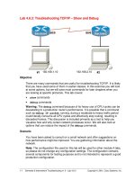
Figure 1.3 Typical loss vs. length of coax and optical fiber links operating at
10 GHz.
are the tradeoffs if we try to reduce this loss; how does this loss impact other link
parameters such as the noise and distortion performance? It is the goal of this book
to provide the background to answer such questions.
We can get an indication of the basis for these losses if we look at the typical
loss of a link versus the length of the optical fiber between the modulation and
photodetection devices. An example of this is shown in Fig. 1.3, which plots the
RF loss vs. length for fiber and coaxial links operating at 10 GHz. The range of
losses shown for the optical fiber link is representative of what has been reported
to date. We can see that the fiber link loss increases slowly with fiber length as we
would expect from the fiber optical loss data of Fig. 1.1, whereas the coax link loss
increases much more quickly with length. However, note that at zero link length,
the coaxial cable loss goes to zero while the optical fiber link loss does not. The
zero length loss for the optical fiber link represents the combined effects of the
RF/optical conversion inefficiencies of the modulation and photodetection devices.
For long length links this zero length conversion loss is less important because
the sum of the conversion and fiber losses is still less than the coaxial loss. But for
shorter length links, where the fiber loss is negligible, the conversion loss dominates
the link loss and exceeds the coaxial loss. Consequently an important aspect of link
design will be understanding the reasons behind the conversion loss and developing
techniques for reducing it.
In comparing an optical link with the coax or waveguide that it often replaces,
there are a couple of important facts that impact link design, in addition to the
loss vs. length issue we just discussed. One fact is that while the fiber is just
as bi-directional as coax, when one includes the modulation and photodetection
4 Introduction
devices, the fiber link is uni-directional.
2
(This is also true of coax, when one
includes the driver and receiver electronics.) However, unlike the coax case, in
the fiber link case the reverse transmission – i.e. from photodetection to modu-
lation device – is truly zero. This is because the common modulation device has
no photodetection capability and the typical photodetection device cannot pro-
duce optical emissions.
3
The impacts of these facts for the link designer are that:
(1) the application as well as the RF performance are part of the link design process
and (2) the modulation and photodetection circuits are separable in that changing
the loading at the photodetection device has no impact on the modulation device
circuit.
Another distinction between an optical link and its RF counterpart is in the
number of parameters needed to describe their use in a system. Coax and waveguide
are completely defined for these purposes in terms of two parameters: their loss
and frequency response. An optical link, which is more analogous to an active
RF component – such as an amplifier – than to passive coax, typically requires at
least four parameters: loss, bandwidth, noise figure and dynamic range. In terms
of these four parameters, we will see that the modulation device has the greatest
impact on all four parameters, with the photodetector a close second in terms of
these same parameters. The fiber, especially when longer lengths are involved, can
have a significant impact on loss, which as we will see in turn affects noise figure.
The fiber can also indirectly affect bandwidth via its dispersion; fiber effects on
dynamic range are negligible.
The emphasis in this book will be on developing the tools and techniques that
will enable one to design links for a variety of applications, based on given device
designs. This is quite different from other books where the emphasis is on designing
devices, with secondary – at best – consideration on applying the device in a link.
While the link models will be firmly rooted in the device physics, the focus here
will be on relating device, and to a lesser extent fiber, parameters to link parameters.
Conceptually the RF signal could be conveyed over an optical link using any one
of the optical carrier’s parameters that are analogous to the parameters commonly
used with an RF carrier: i.e. the optical carrier’s amplitude E
o
, frequency ν,or
phase θ.For specificity, assume an optical plane wave propagating in free space in
the z-direction:
E(z, t) = E
o
exp
j2π
zν
c
− νt + θ
. (1.1)
2
There are techniques, such as wavelength division multiplexing or WDM, by which two or more independent
signals can be conveyed over a single fiber. Thus it is possible to use a pair of links, operating at different
wavelengths, to provide bi-directional transmission over a single fiber. The individual links, however, are still
uni-directional.
3
There have been attempts to design devices that can both emit and detect light. Initial attempts yielded devices
with a considerable compromise in the efficiency of the emitter or detector. However, more recent devices have
reduced this combination penalty considerably; see for example Welstand et al. (1996).
1.1 Background 5
Means exist in the optical domain that duplicate many of the functions in the
RF domain: frequency mixing, LO generation, heterodyne conversion, optical am-
plifiers – one notable exception is the present lack of any method for hard optical
limiting, as there is in the electronic domain. Indeed, optical modulators for each of
the three parameters listed above have been demonstrated. However, the technology
for optical receivers is at present roughly where RF receivers were at the beginning
of the twentieth century.
Virtually all present RF receivers are coherent receivers in which the amplitude
or frequency – or in some cases the phase – of the incoming carrier is detected.
This is in contrast to the early days of radio when direct detection was the norm –
i.e. detection of the presence/absence of the RF carrier without regard to its precise
frequency and certainly without any phase information (e.g. Morse code).
Direct detection of an intensity modulated optical carrier is straightforward; as
we will see in Chapter 2 all that is required is a photodiode (Yu, 1996). Demodula-
tion of an optical carrier, which has been modulated in either frequency or phase,
requires a coherent optical receiver. In turn this requires an optical local oscil-
lator, optical mixer – which can be done in the photodiode – and optical filter.
Although coherent optical receivers have been extensively studied (see for exam-
ple Seeds, 1996; Yamamoto and Kimura, 1981) they have not found widespread
application at present, primarily due to the fact that their marginal performance
improvement over direct detection does not justify their significant additional
complexity.
The results of the coherent optical receiver studies indicated that coherent de-
tection offers greater sensitivity than direct detection. Although coherent detection
links require about the same total optical power at the photodetector, they require
less modulated optical power than direct detection for the same signal-to-noise
ratio, when used in conjunction with a high optical power local oscillator. This
fact was the driving force behind much of the early work on coherent detection.
However, more recently, the availability of optical amplifiers, which can be used
as optical pre-amplifiers before the photodetector, has permitted direct detection
sensitivity to approach that of coherent detection.
4
Although direct detection is much simpler to implement than coherent detection,
it detects only the intensity of the optical wave; all frequency and phase information
of the optical carrier is lost. We can see this by examining the intensity of the plane
wave example from above. The intensity I (W/m
2
)is
I =
1
2
cε
0
E
2
o
(1.2)
4
The degree to which the performance of optically pre-amplified direct detection approaches coherent detection
depends on many factors; primary among them is the noise figure of the optical pre-amplifier.
6 Introduction
or simply the square of the optical wave’s amplitude – when the amplitude is real –
and where ε
0
is the permittivity and c is the speed of light, both in vacuum. Conse-
quently, amplitude and intensity modulation are not synonymous.
5
One important
aspect of this distinction is that the spectrum of the optical waveform for intensity
modulation can be much wider than the RF spectrum of the modulating waveform,
because the optical spectrum contains harmonics of the modulation waveform gen-
erated in the square-law modulation process. This situation is shown diagrammat-
ically in Fig. 1.4(b) by the ellipses that indicate continuation of the sidebands on
both sides of the optical carrier. For low modulation indices these harmonics may
be negligible, in which case the intensity and amplitude modulated spectra have
approximately the same bandwidth. The similarities that intensity and amplitude
modulation do share often lead to these terms being used interchangeably in casual
discussions. This is unfortunate because the unsupported assumption of equivalence
can lead to erroneous conclusions.
Thus intensity modulation of the optical carrier followed by direct detection –
which is often abbreviated IMDD – is the universal choice in applications today
and will be the focus of this book.
There are two broad categories of optical intensity modulation (Cox et al., 1997).
In the simple link example given above, and as shown in Fig. 1.4(a), with direct
modulation, the electrical modulating signal is applied directly to the laser to change
its output optical intensity. This implies that the modulating signal must be within
the modulation bandwidth of the laser. As we will see, only semiconductor diode
lasers have sufficient bandwidth to be of practical interest for direct modulation. The
alternative to direct modulation is external,orindirect, modulation; see Fig. 1.4(c).
With external modulation, the laser operates at a constant optical power (i.e. CW)
and intensity modulation is impressed via a device that is typically external to the
laser. Since there is no modulation requirement on the laser for external modulation,
this removes a major restriction on the choice of lasers that can be used for external
modulation. Both methods achieve the same end result – an intensity modulated
optical carrier – and consequently both use the same detection method, a simple
photodetector. As we will discuss in the chapters to follow, there are a number of
fundamental and implementation issues concerning these two approaches that give
each distinct advantages.
Ideally the electro-optic and opto-electronic conversions at the modulation and
photodetection devices, respectively, would be highly efficient, strictly linear and
5
As an example of true optical AM, one could apply the modulation to a Mach–Zehnder modulator biased at cutoff,
which will produce double-sideband, suppressed carrier (DSSC) AM of the optical wave. Such a signal can be
demodulated by coherently re-injecting the carrier at the receiving end, either optically or by first heterodyning
to lower frequencies.
1.1 Background 7
Figure 1.4 Intensity modulation, direct detection links (b) using (a) direct and
(c) external modulation.
introduce no noise. Further the devices would maintain these characteristics over
all frequencies and for any RF power no matter how large or small.
From the simple link example presented above, we saw that some practical
electro-optic devices fall well short of the ideal conversion efficiency goal. As we
will see in later chapters, practical devices often also fall short of the other ideal
characteristics as well. For example, without proper design practices, we commonly
find unacceptable levels of distortion in analog links – which means that one or
more of the conversion processes is not strictly linear. Casual link design can also
lead to additional noise being added by the optical link, which can reduce the link’s
ability to convey low level signals. At the other end of the RF power range, practical
devices are also limited in the maximum RF power they can handle; typically above
a certain RF power, there is no further increase in modulation and the device is said
to have saturated.
As we go through this book we will develop the basis for the present limitations
of practical devices, then present techniques for reducing these limitations. Our
task as a link designer is complicated by the fact that reducing one parameter, such
8 Introduction
as the noise, often leads to an increase in another parameter, such as the distortion.
The “art” of link design is finding one link design that balances the competing effect
of several parameters.
1.2 Applications overview
There are, of course, many ways to review the current applications of analog opti-
cal links. The wide range of application requirements and frequency ranges makes
it difficult to have a general comparative discussion of the links used in all such
applications. One way to organize an introductory discussion is to recognize that
the different application categories emphasize different technical requirements de-
pending on the primary function the link is fulfilling. Consequently we can group
fiber optic links into three functional categories that dominate the applications at
present: transmit, distribution and receive links.
1.2.1 Transmit optical links
An optical link for transmit applications is aimed at conveying an RF signal from
the signal source to an antenna, as shown in generic block diagram form in Fig. 1.5.
Applications include the up-link for cellular/PCS antenna remoting and the transmit
function of a radar system. Both direct and external modulation have been inves-
tigated for radar transmit applications whereas only direct modulation is presently
used for cellular/PCS transmit applications.
Since high level signals are involved in transmit, noise is not usually a driving
requirement. In radar applications, generally the link needs to convey only a single
frequency at a time; consequently distortion is also not a driving requirement.
However, in multi-function antennas and cellular/PCS up-links, multiple signals
are present simultaneously, so there is the need to meet a distortion requirement,
albeit a relatively modest one in comparison to receive applications.
Virtually all transmit applications do require a relatively high level RF signal to
drive the antenna. As suggested by Fig. 1.3, most fiber optic links have significant
RF-to-RF loss, and it turns out that this high loss also occurs at low frequencies
such as UHF. In addition, the maximum RF power at the photodetector end of the
link is typically limited by thermal and linearity constraints to about −10 dBm.
6
Consequently for a transmit antenna to radiate1Wmeans that 40 dB of RF gain
is needed between the link output and the antenna. Further, if this link has a gain
of −30 dB, then 20 dBm of input power is necesssary to produce −10 dBm at the
link output. However, 20 dBm is above the saturation power of many modulation
6
The unit dBm is power relative to 1 mW, thus −10 dBm represents a power of 0.1 mW.
1.2 Applications overview 9
Figure 1.5 Example block diagram of a fiber optic link used for true-time-delay
beam steering in a phased array antenna.
devices, which means that a lower drive to the link and consequently a higher gain
power amplifier after the link photodetector is typically required. Therefore there
is a real need to decrease the RF/optical conversion loss and increase the output
power capability of links for transmit applications.
The center frequency of the signal sent to the antenna can be anywhere from
10 MHz to 100 GHz. Complete links have been demonstrated up to 20 GHz.
Consequently at center frequencies in this range, the transmit link is typically
designed to convey the center frequency without any frequency translation.
The components necessary for higher frequency links have been demonstrated:
broadband modulation of a diode laser up to 33 GHz (Ralston et al., 1994), of an
external modulator up 70 GHz (Noguchi et al., 1994) and of a photodetector up to
500 GHz (Chou and Liu, 1992) has been reported. However, the efficiencies of these
components are such that if they were combined into a link, the link gain without
any amplifiers would be rather low. For instance, if the 70 GHz modulator were
used in a link with the 500 GHz photodetector with 1 mW of incident optical power,
the gain would be approximately −60 dB at 70 GHz. This level of performance
only serves to extend the needs mentioned above to include reduced loss at high
frequency as well.
1.2.2 Distribution optical links
This type of link is intended to distribute the same RF signal to a multiplicity of sites,
such as distributing the phase reference within a phased array radar. The first large
scale commercial application of analog fiber optic links was the distribution of cable
television (CATV) signals (see for example Darcie and Bodeep, 1990; Olshansky
et al., 1989). As shown in Fig. 1.6, the low loss of optical fibers permitted reducing or
even eliminating the myriad repeater amplifiers that had been required with coaxial
distribution. Like the transmit links, distribution links convey relatively high level
10 Introduction
Primary Ring
Secondary Ring
Public Switched
Telephone Network
Hub
Coax
Fiber
Optical
Node
500–2000 Home
Distribution Area
Master
Headend
Secondary
Headend
Hub
Figure 1.6 Conceptual block diagram of optical-fiber-based CATV distribution
system.
signals, consequently link noise is not a driving parameter. Also like some transmit
links, distribution links that broadcast the phase reference, such as in a radar, have
only a single frequency present at any one time, therefore distortion is not a driving
parameter. However, in other distribution applications, such as CATV, multiple
carriers – which can be as many as 80 in current CATV systems – are present
simultaneously, so distortion becomes a key link parameter. Further, for CATV dis-
tribution, the bandwidth is sufficiently wide that both narrow-band and wide-band
distortion – two terms that will be defined in Chapter6–must be taken into consid-
eration in designing links for this application. Typically, external modulation links
are used in the primary ring and direct modulation is used in the secondary ring.
Distribution links by their very nature have a high optical loss that is dominated by
the splitting loss in the distribution network, which arises from dividing the optical
signal among multiple photodetectors. For example, a fiber network that needs to
distribute a signal to 100 locations would have an optical splitting loss of 20 dB,
assuming ideal optical splitters that introduce no excess loss in the splitting process.
As we will see in Chapter 3, 20 dB of optical loss translates to 40 dB of RF loss
between the RF input and any one of the RF outputs. Although the total modulated
optical power required is high, the power on each individual photodetector is low.
One convenient way to overcome the high splitting loss is by the use of optical
amplifiers. The two basic types of optical amplifiers are semiconductor (see for
example O’Mahony, 1988), which are available at either of the principal fiber