Tài liệu Resource Handbook of Electronics P1 pptx
Bạn đang xem bản rút gọn của tài liệu. Xem và tải ngay bản đầy đủ của tài liệu tại đây (737.08 KB, 30 trang )
Whitaker, Jerry C. “Frontmatter”
The Resource Handbook of Electronics.
Ed. Jerry C. Whitaker
Boca Raton: CRC Press LLC, ©2001
© 2001 by CRC PRESS LLC
ELECTRONICS
The
Resource
Handbook
of
© 2001 by CRC PRESS LLC
ELECTRONICS HANDBOOK SERIES
Series Editor:
Jerry C. Whitaker
Technical Press
Morgan Hill, California
PUBLISHED TITLES
AC POWER SYSTEMS HANDBOOK, SECOND EDITION
Jerry C. Whitaker
THE COMMUNICATIONS FACILITY DESIGN HANDBOOK
Jerry C. Whitaker
THE ELECTRONIC PACKAGING HANDBOOK
Glenn R. Blackwell
POWER VACUUM TUBES HANDBOOK, SECOND EDITION
Jerry C. Whitaker
MICROELECTRONICS
Jerry C. Whitaker
SEMICONDUCTOR DEVICES AND CIRCUITS
Jerry C. Whitaker
SIGNAL MEASUREMENT, ANALYSIS, AND TESTING
Jerry C. Whitaker
THERMAL DESIGN OF ELECTRONIC EQUIPMENT
Ralph Remsburg
THE RESOURCE HANDBOOK OF ELECTRONICS
Jerry C. Whitaker
FORTHCOMING TITLES
ELECTRONIC SYSTEMS MAINTENANCE HANDBOOK
Jerry C. Whitaker
© 2001 by CRC PRESS LLC
ELECTRONICS
Jerry C. Whitaker
Technical Press
Morgan Hill, California
The
Resource
Handbook
of
Boca Raton London New York Washington, D.C.
CRC Press
© 2001 by CRC PRESS LLC
This book contains information obtained from authentic and highly regarded sources. Reprinted material
is quoted with permission, and sources are indicated. A wide variety of references are listed. Reasonable
efforts have been made to publish reliable data and information, but the author and the publisher cannot
assume responsibility for the validity of all materials or for the consequences of their use.
Neither this book nor any part may be reproduced or transmitted in any form or by any means, electronic
or mechanical, including photocopying, microfilming, and recording, or by any information storage or
retrieval system, without prior permission in writing from the publisher.
The consent of CRC Press LLC does not extend to copying for general distribution, for promotion, for
creating new works, or for resale. Specific permission must be obtained in writing from CRC Press LLC
for such copying.
Direct all inquiries to CRC Press LLC, 2000 N.W. Corporate Blvd., Boca Raton, Florida 33431.
Trademark Notice:
Product or corporate names may be trademarks or registered trademarks, and are
used only for identification and explanation, without intent to infringe.
© 2001 by CRC Press LLC
No claim to original U.S. Government works
International Standard Book Number 0-8493-8353-6
Library of Congress Card Number 00-057935
Printed in the United States of America 1 2 3 4 5 6 7 8 9 0
Printed on acid-free paper
Library of Congress Cataloging-in-Publication Data
Whitaker, Jerry C.
The resource handbook of electronics / Jerry C. Whitaker.
p. cm (The Electronics handbook series)
Includes bibliographical references and index.
ISBN 0-8493-8353-6 (alk. paper)
1. Electonics Handbooks, manuals, etc. I. Title. II. Series.
TK7825 .W48 2000
621.381 dc21 00-057935
© 2001 by CRC PRESS LLC
Preface
The hallmark of the CRC Press “Electronics Engineering Series” of books is their
depth of coverage on targeted subjects. Even the more general-interest publication of
the series—The Electronics Handbook—covers the entire realm of electronics in ex
-
ceptional detail.
This book is a departure from those that have gone before it. The Resource Hand
-
book of Electronics is intended to provide quick access to basic information, mostly
through figures and tables. For each of the 20-plus chapters, a broad-brush overview is
given, followed in most cases by extensive tabular data. The Resource Handbook of
Electronics is intended for readers who need specific data at their fingertips, accessible
in a convenient format.
This book is intended for engineers, technicians, operators, and technical managers
involved in the specification, design, installation, operation, maintenance, and man
-
agement of electronics facilities. The book is designed to be a hands-on pocket guide
that holds solutions to specific problems. In this regard, it is a companion publication to
The Electronics Handbook and the other books in the series. For readers who need ex-
tensive background on a given subject, The Electronics Handbook and its related works
provide the necessary level of detail. For readers who need a broad overview of the sub-
ject and essential data relating to it, The Resource Handbook of Electronics is the ideal
publication.
This book is organized in a logical sequence that begins with fundamental electrical
properties and builds to higher levels of sophistication from one chapter to the next.
Chapters are devoted to all of the most common components and devices, in addition to
higher-level applications of those components.
Among the extensive data contained in The Resource Handbook of Electronics are
•
Frequency assignments—A complete and up-to-date listing of frequencies used
by various services in the U.S. and elsewhere
•
Glossary of terms—An extensive dictionary of electronic terms, including ab
-
breviations and acronyms
•
Conversion factors—Detailed tables covering all types of conversion require
-
ments in the field of electronics
The Resource Handbook of Electronics is the most detailed publication of its kind. I
trust you will find it useful on the job, day in and day out.
Jerry C. Whitaker
Morgan Hill, California
© 2001 by CRC PRESS LLC
For updated information on this and other engineering books, visit the author’s
Internet site
www.technicalpress.com
© 2001 by CRC PRESS LLC
About the Author
Jerry Whitaker is a technical writer based in Morgan Hill, California, where he op
-
erates the consulting firm Technical Press. Mr. Whitaker has been involved in various
aspects of the communications industry for more than 25 years. He is a Fellow of the
Society of Broadcast Engineers and an SBE-certified Professional Broadcast Engi
-
neer. He is also a member and Fellow of the Society of Motion Picture and Television
Engineers, and a member of the Institute of Electrical and Electronics Engineers. Mr.
Whitaker has written and lectured extensively on the topic of electronic systems in
-
stallation and maintenance.
Mr. Whitaker is the former editorial director and associate publisher of Broadcast
Engineering and Video Systems magazines. He is also a former radio station chief engi
-
neer and TV news producer.
Mr. Whitaker is the author of a number of books, including:
•
The Communications Facility Design Handbook, CRC Press, 2000.
•
Power Vacuum Tubes Handbook, 2nd edition, CRC Press, 1999.
•
AC Power Systems, 2nd edition, CRC Press, 1998.
•
DTV: The Revolution in Electronic Imaging, 2nd edition, McGraw-Hill, 1999.
•
Editor-in-Chief, NAB Engineering Handbook, 9th edition, National Association
of Broadcasters, 1999.
•
Editor-in-Chief, The Electronics Handbook, CRC Press, 1996.
•
Coauthor, Communications Receivers: Principles and Design, 2nd edition,
McGraw-Hill, 1996.
•
Electronic Displays: Technology, Design, and Applications, McGraw-Hill,
1994.
•
Coeditor, Standard Handbook of Video and Television Engineering, 3rd edition,
McGraw-Hill, 2000.
•
Coeditor, Information Age Dictionary, Intertec/Bellcore, 1992.
•
Maintaining Electronic Systems, CRC Press, 1991.
•
Radio Frequency Transmission Systems: Design and Operation, McGraw-Hill,
1990.
Mr. Whitaker has twice received a Jesse H. Neal Award Certificate of Merit from the
Association of Business Publishers for editorial excellence. He also has been recog
-
nized as Educator of the Year by the Society of Broadcast Engineers.
© 2001 by CRC PRESS LLC
Acknowledgment
The author wishes to express appreciation to the following contributors for their assis
-
tance in the preparation of this book.
K. Blair Benson
E. Stanley Busby
Michael W. Dahlgren
Gene DeSantis
Donald C. McCroskey
C. Robert Paulson
© 2001 by CRC PRESS LLC
Table of Contents
Chapter 1: Fundamental Electrical Properties
Introduction
Electrical Fundamentals
Conductors and Insulators
Direct Current (dc)
Alternating Current (ac)
Static Electricity
Noise in Electronic Circuits
References
Bibliography
Tabular Data
Chapter 2: International Standards and Constants
Introduction
The History of Modern Standards
American National Standards Institute (ANSI)
Professional Society Engineering Committees
References
Bibliography
Tabular Data
Chapter 3: Electromagnetic Spectrum
Introduction
Operating Frequency Bands
Low-End Spectrum Frequencies (1 to 1000 Hz)
Low-End Radio Frequencies (1000 to 100 kHz)
Medium-Frequency Radio (20 kHz to 2 MHz)
High-Frequency Radio (2 to 30 MHz)
Very High and Ultrahigh Frequencies (30 MHz to 3 GHz)
Microwaves (3 to 300 GHz)
Infrared, Visible, and Ultraviolet Light
X-Rays
Radio Wave Propagation
Free Space Path Loss
References
Bibliography
Tabular Data
Chapter 4: Frequency Assignment and Allocations
Introduction
The International Telecommunication Union (ITU)
Purposes of the Union
Structure of the Union
© 2001 by CRC PRESS LLC
The Federal Communications Commission (FCC)
National Table of Frequency Allocations
U.S. Government Table of Frequency Allocations
Chapter 5: Light, Vision, and Photometry
Introduction
Sources of Illumination
The Spectrum
Monochrome and Color Vision
Luminosity Curve
Luminance
Luminance Discrimination
Perception of Fine Detail
Sharpness
Response to Intermittent Excitation
References
Bibliography
Tabular Data
Chapter 6: Circuit Fundamentals
Introduction
Circuit Analysis
AC Circuits
Power Relationship in AC Circuits
Complex Numbers
Phasors
Per Unit System
Principles of Resonance
Series Resonant Circuits
Parallel Resonant Circuits
Passive/Active Circuit Components
References
Bibliography
Chapter 7: Resistors and Resistive Materials
Introduction
Resistor Types
Wire-Wound Resistor
Metal Film Resistor
Carbon Film Resistor
Carbon Composition Resistor
Control and Limiting Resistors
Resistor Networks
Adjustable Resistors
Attenuators
References
Bibliography
Tabular Data
© 2001 by CRC PRESS LLC
Chapter 8: Capacitance and Capacitors
Introduction
Practical Capacitors
Polarized/Nonpolarized Capacitors
Operating Losses
Film Capacitors
Foil Capacitors
Electrolytic Capacitors
Ceramic Capacitors
Polarized-Capacitor Construction
Aluminum Electrolytic Capacitors
Tantalum Electrolytic Capacitors
Capacitor Failure Modes
Temperature Cycling
Electrolyte Failures
Capacitor Life Span
References
Bibliography
Chapter 9: Inductors and Magnetic Properties
Introduction
Electromagnetism
Magnetic Shielding
Inductors and Transformers
Losses in Inductors and Transformers
Air-Core Inductors
Ferromagnetic Cores
Shielding
References
Bibliography
Tabular Data
Chapter 10: Filter Devices and Circuits
Introduction
Filter Type
Filter Alignment
Filter Order
Filter Design Implementation
LC Filters
Electrical Resonators
Stripline technology
Electro-Mechanical Filters
Quartz Crystal Resonators
Monolithic Crystal Filters
Ceramic Filters
References
© 2001 by CRC PRESS LLC
Chapter 11: Thermal Properties
Introduction
Heat Transfer Mechanisms
Conduction
Convection
Radiation
The Physics of Boiling Water
Application of Cooling Principles
Forced-Air Cooling Systems
Air-Handling System
References
Chapter 12: Semiconductor Devices
Introduction
The pn Junction
Zener Diodes and Reverse Breakdown
Current Regulators
Varistor
Bipolar Transistors
NPN and PNP Transistors
Transistor Impedance and Gain
Transistor Configurations
Switching and Inductive-Load Ratings
Noise
Field-Effect Transistors
FET Impedance and Gain
Integrated Circuits
Digital Integrated Circuits
Linear Integrated Circuits
References
Bibliography
Tabular Data
Chapter 13: Analog Circuits
Introduction
Single-Stage Transistor/FET Amplifier
Impedance and Gain
Common-Base or Common-Gate Connection
Common-Collector or Common-Drain Connection
Bias and Large Signals
Operational Amplifiers
References
Bibliography
Chapter 14: Logic Concepts and Devices
Introduction
Analog-to-Digital (A/D) Conversion
Digital-to-Analog (D/A) Conversion
© 2001 by CRC PRESS LLC
Combinational Logic
Boolean Algebra
Logic Device Families
Diode-Transistor Logic (DTL)
Transistor-Transistor Logic (TTL)
NMOS and PMOS
Complementary MOS (CMOS)
Emitter-Coupled Logic (ECL)
Scaling of Digital Circuit Packages
Representation of Numbers and Numerals
Nibble
Byte
Word
Negative Numbers
Floating Point
Compare
Jump
Errors in Digital Systems
Error Detection and Correction
Error Concealment
References
Bibliography
Chapter 15: Amplitude Modulation
Introduction
Fundamental Principles
High-Level AM Modulation
Vestigial-Sideband Amplitude Modulation (VSBAM)
Single-Sideband Amplitude Modulation (SSBAM)
Quadrature Amplitude Modulation (QAM)
References
Bibliography
Chapter 16: Frequency Modulation
Introduction
Modulation Index
Phase Modulation
Modifying FM Waves
Preemphasis and Deemphasis
Modulation Circuits
Direct-FM Modulator
VCO Direct-FM Modulator
References
Bibliography
Chapter 17: Pulse Modulation
Introduction
Digital Modulation Systems
Pulse Amplitude Modulation (PAM)
© 2001 by CRC PRESS LLC
Pulse Time Modulation (PTM)
Pulse Code Modulation (PCM)
Delta Modulation (DM)
Digital Coding Systems
Baseband Digital Pulse Modulation
References
Bibliography
Chapter 18: Network Communications
Introduction
Physical Layer
Installation Considerations
Data Link Layer
Installation Considerations
Network Layer
Installation Considerations
Transport Layer
Installation Considerations
Session Layer
Installation Considerations
Presentation Layer
Installation Considerations
Application Layer
Installation Considerations
Transmission System Options
System Design Alternatives
Frequency Division Multiplexing
Time Division Multiplexing
Wave(length) Division Multiplexing
Selecting Cable for Digital Signals
Data Patch Panel
Bibliography
Chapter 19: Optical Devices and Systems
Introduction
Types of Fibers
Step Index Multi-mode Fiber
Step Index Single (Mono) -mode Fiber
Graded Index Multi-mode Fiber
Characteristics of Attenuation
Types of Cable
Breakout Design
MFPT, Central Loose Tube Design
MFPT, Stranded Loose Tube Design
SFPT, Stranded Loose Tube Design
Star, or Slotted Core, Design
Tight Tube, or Stuffed, Design
Application Considerations
Specifying Fiber-Optic Cable
© 2001 by CRC PRESS LLC
Installation Specifications
Environmental Specifications
Fiber Optic Connectors
Connector Properties
Performance Considerations
Bibliography
Chapter 20: System Reliability
Introduction
Terminology
Quality Assurance
Inspection Process
Reliability Evaluation
Parts-Count Method
Stress-Analysis Method
Failure Analysis
Standardization
Reliability Analysis
Statistical Reliability
Roller-Coaster Hazard Rate
Environmental Stress Screening
Latent Defects
Operating Environment
Failure Modes
Maintenance Considerations
Common-Mode Failure
Spare Parts
ISO 9000 Series
References
Chapter 21: Glossary of Terms
Chapter 22: Abbreviations and Acronyms
Chapter 23: Conversion Factors
Standard Units
Standard Prefixes
Common Standard Units
Conversion Reference Data
Reference Tables
© 2001 by CRC PRESS LLC
For baby
Ashley Grace Whitaker
The journey begins
© 2001 by CRC PRESS LLC
Whitaker, Jerry C. “Fundamental Electrical Properties”
The Resource Handbook of Electronics.
Ed. Jerry C. Whitaker
Boca Raton: CRC Press LLC, ©2001
© 2000 by CRC PRESS LLC
Chapter
1
Fundamental Electrical Properties
1.1 Introduction
The atomic theory of matter specifies that each of the many chemical elements is
composed of unique and identifiable particles called atoms. In ancient times only 10
were known in their pure, uncombined form; these were carbon, sulfur, copper, anti-
mony, iron, tin, gold, silver, mercury, and lead. Of the several hundred now identified,
less than 50 are found in an uncombined, or chemically free, form on earth.
Each atom consists of a compact nucleus of positively and negatively charged parti-
cles (protons and electrons, respectively). Additional electrons travel in well-defined
orbits around the nucleus. The electron orbits are grouped in regions called shells, and
the number of electrons in each orbit increases with the increase in orbit diameter in ac-
cordance with quantum-theory laws of physics. The diameter of the outer orbiting path
of electrons in an atom is in the order of one-millionth (10
–6
) millimeter, and the nu-
cleus, one-millionth of that. These typical figures emphasize the minute size of the
atom.
1.2 Electrical Fundamentals
The nucleus and the free electrons for an iron atom are shown in the schematic dia
-
gram in Figure 1.1. Note that the electrons are spinning in different directions. This
rotation creates a magnetic field surrounding each electron. If the number of electrons
with positive spins is equal to the number with negative spins, then the net field is
zero and the atom exhibits no magnetic field.
In the diagram, although the electrons in the first, second, and fourth shells balance
each other, in the third shell five electrons have clockwise positive spins, and one a
counterclockwise negative spin, which gives the iron atom in this particular electron
configuration a cumulative magnetic effect.
The parallel alignment of the electron spins over regions, known as domains, con
-
taining a large number of atoms. When a magnetic material is in a demagnetized state,
the direction of magnetization in the domain is in a random order. Magnetization by an
© 2000 by CRC PRESS LLC
external field takes place by a change or displacement in the isolation of the domains,
with the result that a large number of the atoms are aligned with their charged electrons
in parallel.
1.2.1 Conductors and Insulators
In some elements, such as copper, the electrons in the outer shells of the atom are so
weakly bound to the nucleus that they can be released by a small electrical force, or
voltage. A voltage applied between two points on a length of a metallic conductor
produces the flow of an electric current, and an electric field is established around the
conductor. The conductivity is a constant for each metal that is unaffected by the cur
-
rent through or the intensity of any external electric field.
In some nonmetallic materials, the free electrons are so tightly bound by forces in
the atom that, upon the application of an external voltage, they will not separate from
their atom except by an electrical force strong enough to destroy the insulating proper
-
ties of the material. However, the charges will realign within the structure of their atom.
This condition occurs in the insulating material (dielectric) of a capacitor when a volt
-
age is applied to the two conductors encasing the dielectric.
Semiconductors are electronic conducting materials wherein the conductivity is de
-
pendent primarily upon impurities in the material. In addition to negative mobile
charges of electrons, positive mobile charges are present. These positive charges are
called holes because each exists as an absence of electrons. Holes (+) and electrons (–),
Figure 1.1 Schematic of the iron (Fe) atom.
© 2000 by CRC PRESS LLC
because they are oppositely charged, move in opposite directions in an electric field.
The conductivity of semiconductors is highly sensitive to, and increases with, tempera
-
ture.
1.2.2 Direct Current (dc)
Direct current is defined as a unidirectional current in which there are no significant
changes in the current flow. In practice, the term frequently is used to identify a volt
-
age source, in which case variations in the load can result in fluctuations in the current
but not in the direction.
Direct current was used in the first systems to distribute electricity for household
and industrial power. For safety reasons, and the voltage requirements of lamps and
motors, distribution was at the low nominal voltage of 110. The losses in distribution
circuits at this voltage seriously restricted the length of transmission lines and the size
of the areas that could be covered. Consequently, only a relatively small area could be
served by a single generating plant. It was not until the development of alternating-cur
-
rent systems and the voltage transformer that it was feasible to transport high levels of
power at relatively low current over long distances for subsequent low-voltage distribu-
tion to consumers.
1.2.3 Alternating Current (ac)
Alternating current is defined as a current that reverses direction at a periodic rate.
The average value of alternating current over a period of one cycle is equal to zero.
The effective value of an alternating current in the supply of energy is measured in
terms of the root mean square (rms) value. The rms is the square root of the square of
all the values, positive and negative, during a complete cycle, usually a sine wave. Be-
cause rms values cannot be added directly, it is necessary to perform an rms addition
as shown in the equation:
VVVV
rms total
rms rms rms n
=++
1
2
2
22
L
(1.1)
As in the definition of direct current, in practice the term frequently is used to iden
-
tify a voltage source.
The level of a sine-wave alternating current or voltage can be specified by two other
methods of measurement in addition to rms. These are average and peak. A sine-wave
signal and the rms and average levels are shown in Figure 1.2. The levels of complex,
symmetrical ac signals are specified as the peak level from the axis, as shown in the fig
-
ure.
1.2.4 Static Electricity
The phenomenon of static electricity and related potential differences concerns con
-
figurations of conductors and insulators where no current flows and all electrical
© 2000 by CRC PRESS LLC
forces are unchanging; hence the term static. Nevertheless, static forces are present
because of the number of excess electrons or protons in an object. A static charge can
be induced by the application of a voltage to an object. A flow of current to or from
the object can result from either a breakdown of the surrounding nonconducting ma
-
terial or by the connection of a conductor to the object.
Two basic laws regarding electrons and protons are:
•
Like charges exert a repelling force on each other; electrons repel other electrons
and protons repel other protons
• Opposite charges attract each other; electrons and protons are attracted to each
other
Therefore, if two objects each contain exactly as many electrons as protons in each
atom, there is no electrostatic force between the two. On the other hand, if one object
is charged with an excess of protons (deficiency of electrons) and the other an excess
of electrons, there will be a relatively weak attraction that diminishes rapidly with dis
-
tance. An attraction also will occur between a neutral and a charged object.
Another fundamental law, developed by Faraday, governing static electricity is that
all of the charge of any conductor not carrying a current lies in the surface of the con
-
ductor. Thus, any electric fields external to a completely enclosed metal box will not
penetrate beyond the surface. Conversely, fields within the box will not exert any force
on objects outside the box. The box need not be a solid surface; a conduction cage or
grid will suffice. This type of isolation frequently is referred to as a Faraday shield.
1.2.5 Noise in Electronic Circuits
Noise has become the standard term for signals that are random and that are com
-
bined with the circuit signal to affect the overall performance of a system. As the
study of noise has progressed, engineers have come to realize that there are many
sources of noise in circuits. The following definitions are commonly used in discus
-
sions of circuit noise:
Figure 1.2 Root mean square (rms) measurements. The relationship of rms and aver
-
age values is shown.
© 2000 by CRC PRESS LLC
•
White noise: a signal that has its energy evenly distributed over the entire fre
-
quency spectrum, within the frequency range of interest (typically below fre
-
quencies in the infrared range). Because white noise is totally random, it may
seem inappropriate to refer to its frequency range, because it is not really periodic
in the ordinary sense. Nevertheless, by examining an oscilloscope trace of white
noise, it can be verified that every trace is different, as the noise never repeats it
-
self, and yet each trace looks the same. There is a strong theoretical foundation to
represent the frequency content of such signals as covering the frequency spec
-
trum evenly. In this way the impact on other periodic signals can be analyzed. The
term white noise arises from the fact that, similar to white light, which has equal
amounts of all light frequencies, white noise has equal amounts of noise at all fre
-
quencies within circuit operating ranges.
•
Interference: the name given to any predictable, periodic signal that occurs in an
electronic circuit in addition to the signal the circuit is designed to process. This is
distinguished from a noise signal by the fact that it occupies a relatively small fre
-
quency range, and because it is predictable it can often be filtered out. Usually, in
-
terference comes from another electronic system such as an interfering radio
source.
•
Thermal noise: any noise that is generated within a circuit and is temperature-de-
pendent. This signal usually is the result of the influence of temperature directly
on the operating characteristics of circuit components, which because of the ran-
dom motion of molecules as a result of temperature, in turn creates a random fluc-
tuation of the signal being processed.
•
Shot noise: a type of circuit noise that is not temperature-dependent, and is not
white noise in the sense that it tends to diminish at higher frequencies. This noise
usually occurs in components whose operation depends on a mean particle resi
-
dence time for the active electrons within the device. The cutoff frequency above
which noise disappears is closely related to the inverse of this characteristic parti
-
cle residence time.
1.3 References
1. Whitaker, Jerry C. (ed.), The Electronics Handbook, CRC Press, Boca Raton, FL,
1996.
1.4 Bibliography
Benson, K. Blair, and Jerry C. Whitaker, Television and Audio Handbook for Techni
-
cians and Engineers, McGraw-Hill, New York, NY, 1990.
Benson, K. Blair, Audio Engineering Handbook, McGraw-Hill,New York, NY, 1988.
Whitaker, Jerry C., Television Engineers’ Field Manual, McGraw-Hill, New York,
NY, 2000.
© 2000 by CRC PRESS LLC
1.5 Tabular Data
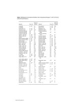
Table 1.1 Symbols and Terminology for Physical and Chemical Quantities: Classical
Mechanics (
From
[1].
Used with permission
.)
© 2000 by CRC PRESS LLC
Table 1.2 Symbols and Terminology for Physical and Chemical Quantities: Electricity
and Magnetism (
From
[1].
Used with permission
.)
© 2000 by CRC PRESS LLC