Tài liệu Kinematics and Mechanisms P1 pptx
Bạn đang xem bản rút gọn của tài liệu. Xem và tải ngay bản đầy đủ của tài liệu tại đây (1.29 MB, 30 trang )
Ravani, B. “Kinematics and Mechanisms”
The Engineering Handbook.
Ed. Richard C. Dorf
Boca Raton: CRC Press LLC, 2000
© 1998 by CRC PRESS LLC
THE LONG TRAVEL DAMPER (LTD) CLUTCHThe introduction of the Long Travel Damper
(LTD) clutch by Rockwell has addressed driver concerns of engine and drivetrain torsional vibration. The
15.5", diaphragm-spring, two-plate, pull-type clutch absorbs and dampens vibrations and torque loads
passed through from the engine flywheel, providing a smoother ride for drivers and increased drivetrain
component life. The LTD is available in three different capacities for use in low, medium and high
horsepower ranges and features a fifth rivet to help alleviate clutch drag. (Photo courtesy of Rockwell
Automotive.)
© 1998 by CRC PRESS LLC
IV
Kinematics and Mechanisms
Bahram Ravani
University of California, Davis
20 Linkages and Cams J. M. McCarthy and G. L. Long
Linkages • Spatial Linkages • Displacement Analysis • Cam Design • Classification of Cams and Followers
• Displacement Diagrams
21 Tribology: Friction, Wear, and Lubrication B. Bhushan
History of Tribology and Its Significance to Industry • Origins and Significance of Micro/nanotribology •
Friction • Wear • Lubrication • Micro/nanotribology
22 Machine Elements G. R. Pennock
Threaded Fasteners • Clutches and Brakes
23 Crankshaft Journal Bearings P. K. Subramanyan
Role of the Journal Bearings in the Internal Combustion Engine • Construction of Modern Journal Bearings
• The Function of the Different Material Layers in Crankshaft Journal Bearings • The Bearing Materials •
Basics of Hydrodynamic Journal Bearing Theory • The Bearing Assembly • The Design Aspects of Journal
Bearings • Derivations of the Reynolds and Harrison Equations for Oil Film Pressure
24 Fluid Sealing in Machines, Mechanical Devices, and Apparatus A. O. Lebeck
Fundamentals of Sealing • Static Seals • Dynamic Seals • Gasket Practice • O-Ring Practice • Mechanical
Face Seal Practice
THIS SECTION COMBINES KINEMATICS AND MECHANISMS and certain aspects of
mechanical design to provide an introductory coverage of certain aspects of the theory of machines
and mechanisms. This is the branch of engineering that deals with design and analysis of moving
devices (or mechanisms) and machinery and their components. Kinematic analysis is usually the
first step in the design and evaluation of mechanisms and machinery, and involves studying the
relative motion of various components of a device or evaluating the geometry of the force system
acting on a mechanism or its components. Further analysis and evaluation may involve calculation
of the magnitude and sense of the forces and the stresses produced in each part of a mechanism or
machine as a result of such forces. The overall subject of the theory of machines and mechanisms
is broad and would be difficult to cover in this section. Instead, the authors in this section provide
an introduction to some topics in this area to give readers an appreciation of the broad nature of
this subject as well as to provide a readily available reference on the topics covered.
The first chapter is an introductory coverage of linkages and cams. These are mechanisms found
in a variety of applications, from door hinges to robot manipulators and the valve mechanisms used
in present-day motor vehicles. The scope of the presentation is displacement analysis dealing with
understanding the relative motion between the input and output in such mechanisms. The second
chapter goes beyond kinematic analysis and deals with the effects of the interactions between two
surfaces in relative motion. This subject is referred to as tribology, and it is an important topic in
© 1998 by CRC PRESS LLC
mechanical design, the theory of machines, and other fields. Tribology is an old field but still has
many applications in areas where mechanical movement is achieved by relative motion between
two surfaces. Present applications of tribology range from understanding the traction properties of
tires used in automobiles to understanding the interfacial phenomena in magnetic storage systems
and devices. The third chapter in this section deals with mechanical devices used for stopping
relative motion between the contacting surfaces of machine elements or for coupling two moving
mechanical components. These include mechanical fasteners, brakes, and clutches. Many
mechanical devices and machines require the use of bolts and nuts (which are fasteners) for their
construction. Brakes are usually used to stop the relative motion between two moving surfaces, and
clutches reduce any mismatch in the speed of two mechanical elements. These components are
used in a variety of applications; probably their best-known application is their use in the motor
vehicle.
The fourth chapter deals with another mechanical element in the automotive industry, namely,
the journal bearing used in the crankshaft of the automotive engine (which is usually an internal
combustion engine). The last chapter in this sectiondeals with mechanical seals used to protect
against leakage of fluids from mechanical devices and machines. When two mechanical
components are brought into contact or relative motion as part of a machine, the gap between the
contacting surfaces must be sealed if fluid is used for lubrication or other purposes in the machine.
This chapter provides an introduction to the mechanical seals used to protect against leakage of
fluids.
In summary, the authors in this section have provided easy-to-read introductions to selected
topics in the field of theory of machines and mechanisms that can be used as a basis for further
studies or as a readily available reference on the subject.
© 1998 by CRC PRESS LLC
McCarthy, J. M., Long, G. L. “Linkages and Cams”
The Engineering Handbook.
Ed. Richard C. Dorf
Boca Raton: CRC Press LLC, 2000
© 1998 by CRC PRESS LLC
20
Linkages and Cams
20.1 Linkages
20.2 Spatial Linkages
20.3 Displacement Analysis
20.4 Cam Design
20.5 Classification of Cams and Followers
20.6 Displacement Diagrams
J. Michael McCarthy
University of California, Irvine
Gregory L. Long
University of California, Irvine
Mechanical movement of various machine components can be coordinated using linkages and
cams. These devices are assembled from hinges, ball joints, sliders, and contacting surfaces and
transform an input movement such as a rotation into an output movement that may be quite
complex.
20.1 Linkages
Rigid links joined together by hinges parallel to each other are constrained to move in parallel
planes and the system is called a planar linkage. A generic value for the degree of freedom, or
mobility, of the system is given by the formula
F = 3(n ¡1) ¡ 2j, where n is the number of links
and j is the number of hinges.
Two links and one hinge form the simplest open chain linkage. Open chains appear as the
structure of robot manipulators. In particular, a three-degree-of-freedom planar robot is formed by
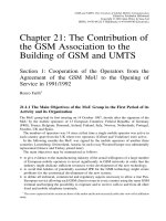
four bodies joined in a series by three hinges, as in Fig. 20.1(b).
If the series of links close to form a loop, the linkage is a simple closed chain. The simplest case
is a quadrilateral
(n=4, j =4) with one degree of freedom (See Figs. 20.1(a) and 20.3); notice
that a triangle has mobility zero. A single loop with five links has two degrees of freedom and one
with six links has three degrees of freedom. This latter linkage also appears when two planar
robots hold the same object.
A useful class of linkages is obtained by attaching a two-link chain to a four-link quadrilateral in
various ways to obtain a one-degree-of-freedom linkage with two loops. The two basic forms of
this linkage are known as the Stephenson and Watt six-bar linkages, shown in Fig. 20.2.
© 1998 by CRC PRESS LLC
Figure 20.2
(a) A Watt six-bar linkage; and (b) a Stephenson six-bar linkage.
Figure 20.1
(a) Planar four-bar linkage; and (b) planar robot.
Figure 20.3 Dimensions used to analyze a planar 4R linkage.
© 1998 by CRC PRESS LLC
longer constrained to move in parallel planes and forms a spatial linkage. The robot manipulator
with six hinged joints (denoted R for revolute joint) is an example of a spatial 6R open chain.
Spatial linkages are often constructed using joints that constrain a link to a sphere about a point,
such as a ball-in-socket joint, or a gimbal mounting formed by three hinges with concurrent
axeseach termed a spherical joint (denoted S). The simplest spatial closed chain is the RSSR
linkage, which is often used in place of a planar four-bar linkage to allow for misalignment of the
cranks (Fig. 20.4).
Figure 20.4
A spatial RSSR linkage.
Another useful class of spatial mechanisms is produced by four hinges with concurrent axes that
form a spherical quadrilateral known as a spherical linkage. These linkages provide a controlled
reorientation movement of a body in space (Fig. 20.5).
In each of these linkages a sliding joint, which constrains a link to a straight line rather than a
circle, can replace a hinge to obtain a different movement. For example, a slider-crank linkage is a
four-bar closed chain formed by three hinges and a sliding joint.
20.2 Spatial Linkages
The axes of the hinges connecting a set of links need not be parallel. In this case the system is no
Figure 20.5 A spherical 4R linkage.
20.3 Displacement Analysis
The closed loop of the planar 4R linkage (Fig. 20.3) introduces a constraint between the crank
angles
µ and à given by the equation
© 1998 by CRC PRESS LLC
A cos à + B sin à = C (20:1)
where
A =
2gb ¡ 2ab cos µ
B =
¡2ab sin µ
C =
h
2
¡g
2
¡b
2
¡a
2
+ 2ga cos µ
This equation can be solved to give an explicit formula for the angle à of the output crank in terms
of the input crank rotation
µ:
Ã(µ) = tan
¡1
µ
B
A
¶
§cos
¡1
µ
C
p
A
2
+ B
2
¶
(20:2)
The constraint equations for the spatial RSSR and spherical 4R linkages have the same form as that
of the planar 4R linkage, but with coefficients as follows. For spatial RSSR linkage (Fig. 20.4):
A =
¡2ab cos ° cos µ ¡2br
1
sin °
B =
2bg ¡2ab sin µ
C =
h
2
¡g
2
¡b
2
¡a
2
¡ r
2
1
¡r
2
2
+ 2r
1
r
2
cos °
+2ar
2
sin ° cos µ + 2ga sin µ
For spherical 4R linkage (Fig. 20.5):
A =
sin ® sin ¯ cos ° cos µ ¡ cos ® sin ¯ sin °
B =
sin ® sin ¯ sin µ
C =
cos ´ ¡sin ® cos ¯ sin ° cos µ
¡cos ® cos ¯ cos °
The formula for the output angle à in terms of µ for both cases is identical to that already given for
the planar 4R linkage.
20.4 Cam Design
A cam pair (or cam-follower) consists of two primary elements called the cam and follower. The
cam's motion, which is usually rotary, is transformed into either follower translation, oscillation, or
combination, through direct mechanical contact. Cam pairs are found in numerous manufacturing
and commercial applications requiring motion, path, and/or function generation. Cam pair
mechanisms are usually simple, inexpensive, compact, and robust for the most demanding design
applications. Moreover, a cam profile can be designed to generate virtually any desired follower
motion, by either graphical or analytical methods.
20.5 Classification of Cams and Followers
The versatility of cam pairs is evidenced by the variety of shapes, forms, and motions for both cam
and follower. Cams are usually classified according to their basic shape as illustrated in Fig. 20.6:
(a) plate cam, (b) wedge cam, (c) cylindric or barrel cam, and (d) end or face cam.
© 1998 by CRC PRESS LLC
Figure 20.6 Basic types of cams.
Followers are also classified according to their basic shape with optional modifiers describing
their motion characteristics. For example, a follower can oscillate [Figs. 20.7(a−b)] or translate
[20.7(c−g)]. As required by many applications, follower motion may be offset from the cam shaft's
center as illustrated in Fig. 20.7(g). For all cam pairs, however, the follower must maintain
constant contact with cam surface. Constant contact can be achieved by gravity, springs, or other
mechanical constraints such as grooves.
© 1998 by CRC PRESS LLC
20.6 Displacement Diagrams
The cam's primary function is to create a well-defined follower displacement. If the cam's
displacement is designated by
µ and follower displacement by y, a given cam is designed such that
a displacement function
y = f(µ) (20:3)
Figure 20.7 Basic types of followers.
© 1998 by CRC PRESS LLC
is satisfied. A graph of y versus µ is called the follower displacement diagram (Fig. 20.8). On a
displacement diagram, the abscissa represents one revolution of cam motion
(µ) and the ordinate
represents the corresponding follower displacement
(y). Portions of the displacement diagram,
when follower motion is away from the cam's center, are called rise. The maximum rise is called
lift. Periods of follower rest are referred to as dwells, and returns occur when follower motion is
toward the cam's center.
Figure 20.8
Displacement diagram.
The cam profile is generated from the follower displacement diagram via graphical or analytical
methods that use parabolic, simple harmonic, cycloidal, and/or polynomial profiles. For many
applications, the follower's velocity, acceleration, and higher time derivatives are necessary for
proper cam design.
Cam profile generation is best illustrated using graphical methods where the cam profile can be
constructed from the follower displacement diagram using the principle of kinematic inversion. As
shown in Fig. 20.9, the prime circle is divided into a number of equal angular segments and
assigned station numbers. The follower displacement diagram is then divided along the abscissa
into corresponding segments. Using dividers, the distances are then transferred from the
displacement diagram directly onto the cam layout to locate the corresponding trace point position.
A smooth curve through these points is the pitch curve. For the case of a roller follower, the roller
is drawn in its proper position at each station and the cam profile is then constructed as a smooth
curve tangent to all roller positions. Analytical methods can be employed to facilitate
computer-aided design of cam profiles.
© 1998 by CRC PRESS LLC
Defining Terms
Linkage Terminology
Standard terminology for linkages includes the following:
Degree of freedom: The number of parameters, available as input, that prescribe the
configuration of a given linkage, also known as its mobility.
Planar linkage: A collection of links constrained to move in parallel planes.
Revolute joint: A hinged connection between two links that constrains their relative movement to
the plane perpendicular to the hinge axis.
Spatial linkage: A linkage with at least one link that moves out of a plane.
Spherical joint: A connection between two links that constrains their relative movement to a
sphere about a point at the center of the joint.
Spherical linkage: A collection of links constrained to move on concentric spheres.
Cam Terminology
The standard cam terminology is illustrated in Fig. 20.10 and defined as follows:
Base circle: The smallest circle, centered on the cam axis, that touches the cam profile (radius
R
b
).
Cam profile: The cam's working surface.
Pitch circle: The circle through the pitch point, centered on the cam axis (radius
R
p
).
Pitch curve: The path of the trace point.
Pitch point: The point on the pitch curve where pressure angle is maximum.
Pressure angle: The angle between the normal to the pitch curve and the instantaneous direction
Figure 20.9 Cam layout.
© 1998 by CRC PRESS LLC
of trace point motion.
Prime circle: The smallest circle, centered on the cam axis, that touches the pitch curve (radius
R
a
).
Trace point: The contact point of a knife-edge follower, the center of a roller follower, or a
reference point on a flat-faced follower.
Figure 20.10
Cam terminology.
References
Chironis, N. P. 1965. Mechanisms, Linkages, and Mechanical Controls. McGraw-Hill, New York.
Erdman, A. G. and Sandor, G. N. 1984. Mechanism Design: Analysis and Synthesis, vol. 1.
Prentice Hall, Englewood Cliffs, NJ.
© 1998 by CRC PRESS LLC
Paul, B. 1979. Kinematics and Dynamics of Planar Machinery. Prentice Hall, Englewood Cliffs,
NJ.
Shigley, J. E. and Uicker, J. J. 1980. Theory of Machines and Mechanisms. McGraw-Hill, New
York.
Suh, C. H. and Radcliffe, C. W. 1978. Kinematics and Mechanism Design. John Wiley & Sons,
New York.
Further Information
An interesting array of linkages that generate specific movements can be found in Mechanisms and
Mechanical Devices Sourcebook by Nicholas P. Chironis.
Design methodologies for planar and spatial linkages to guide a body in a desired way are found
in Mechanism Design: Analysis and Synthesis by George Sandor and Arthur Erdman and in
Kinematics and Mechanism Design by Chung Ha Suh and Charles W. Radcliffe.
Theory of Machines and Mechanisms by Joseph E. Shigley and John J. Uicker is particularly
helpful in design of cam profiles for various applications.
Proceedings of the ASME Design Engineering Technical Conferences are published annually by
the American Society of Mechanical Engineers. These proceedings document the latest
developments in mechanism and machine theory.
The quarterly ASME Journal of Mechanical Design reports on advances in the design and
analysis of linkage and cam systems. For a subscription contact American Society of Mechanical
Engineers, 345 E. 47th St., New York, NY 10017.
© 1998 by CRC PRESS LLC
Bhushan, B. “Tribology: Friction, Wear, and Lubrication”
The Engineering Handbook.
Ed. Richard C. Dorf
Boca Raton: CRC Press LLC, 2000
© 1998 by CRC PRESS LLC
21
Tribology: Friction, Wear, and
Lubrication
21.1 History of Tribology and Its Significance to Industry
21.2 Origins and Significance of Micro/nanotribology
21.3 Friction
Definition of Friction • Theories of Friction • Measurements of Friction
21.4 Wear
Adhesive Wear • Abrasive Wear • Fatigue Wear • Impact Wear • Corrosive Wear • Electrical Arc−Induced
Wear
• Fretting and Fretting Corrosion
21.5 Lubrication
Solid Lubrication • Fluid Film Lubrication
21.6 Micro/nanotribology
Bharat Bhushan
Ohio State University
In this chapter we first present the history of macrotribology and micro/nanotribology and their
significance. We then describe mechanisms of friction, wear, and lubrication, followed by
micro/nanotribology.
21.1 History of Tribology and Its Significance to
Industry
Tribology is the science and technology of two interacting surfaces in relative motion and of
related subjects and practices. The popular equivalent is friction, wear, and lubrication. The word
tribology, coined in 1966, is derived from the Greek word tribos meaning "rubbing," so the literal
translation would be the science of rubbing [Jost, 1966]. It is only the name tribology that is
relatively new, because interest in the constituent parts of tribology is older than recorded history
[Dowson, 1979]. It is known that drills made during the Paleolithic period for drilling holes or
producing fire were fitted with bearings made from antlers or bones, and potters' wheels or stones
for grinding cereals clearly had a requirement for some form of bearings [Davidson, 1957]. A ball
thrust bearing dated about 40
A.D. was found in Lake Nimi near Rome.
Records show the use of wheels from 3500
B.C., which illustrates our ancestors' concern with
reducing friction in translationary motion. The transportation of large stone building blocks and
monuments required the know-how of frictional devices and lubricants, such as water-lubricated
© 1998 by CRC PRESS LLC
sleds. Figure 21.1 illustrates the use of a sledge to transport a heavy statue by Egyptians circa 1880
B.C. [Layard, 1853]. In this transportation, 172 slaves are being used to drag a large statue weighing
about 600 kN along a wooden track. One man, standing on the sledge supporting the statue, is seen
pouring a liquid into the path of motion; perhaps he was one of the earliest lubrication engineers.
[Dowson (1979) has estimated that each man exerted a pull of about 800 N. On this basis the total
effort, which must at least equal the friction force, becomes
172 £ 800
N. Thus, the coefficient of
friction is about 0.23.] A tomb in Egypt that was dated several thousand years
B.C. provides the
evidence of use of lubricants. A chariot in this tomb still contained some of the original animal-fat
lubricant in its wheel bearings.
Figure 21.1
Egyptians using lubricant to aid movement of Colossus, El-Bersheh, c. 1880 B.C.
During and after the glory of the Roman empire, military engineers rose to prominence by
devising both war machinery and methods of fortification, using tribological principles. It was the
Renaissance engineer and artist Leonardo da Vinci (1452
−1519), celebrated in his days for his
genius in military construction as well as for his painting and sculpture, who first postulated a
scientific approach to friction. Leonardo introduced for the first time the concept of coefficient of
friction as the ratio of the friction force to normal load. In 1699 Amontons found that the friction
force is directly proportional to the normal load and is independent of the apparent area of contact.
These observations were verified by Coulomb in 1781, who made a clear distinction between static
friction and kinetic friction.
Many other developments occurred during the 1500s, particularly in the use of improved bearing
materials. In 1684 Robert Hooke suggested the combination of steel shafts and bell-metal bushes
as preferable to wood shod with iron for wheel bearings. Further developments were associated
with the growth of industrialization in the latter part of the eighteenth century. Early developments
in the petroleum industry started in Scotland, Canada, and the U.S. in the 1850s [Parish, 1935;
Dowson, 1979].
Though essential laws of viscous flow had earlier been postulated by Newton, scientific
© 1998 by CRC PRESS LLC
understanding of lubricated bearing operations did not occur until the end of the nineteenth
century. Indeed, the beginning of our understanding of the principle of hydrodynamic lubrication
was made possible by the experimental studies of Tower [1884] and the theoretical interpretations
of Reynolds [1886] and related work by Petroff [1883]. Since then developments in hydrodynamic
bearing theory and practice have been extremely rapid in meeting the demand for reliable bearings
in new machinery.
Wear is a much younger subject than friction and bearing development, and it was initiated on a
largely empirical basis.
Since the beginning of the 20th century, from enormous industrial growth leading to demand for
better tribology, our knowledge in all areas of tribology has expanded tremendously [Holm, 1946;
Bowden and Tabor, 1950, 1964; Bhushan, 1990, 1992; Bhushan and Gupta, 1991].
Tribology is crucial to modern machinery, which uses sliding and rolling surfaces. Examples of
productive wear are writing with a pencil, machining, and polishing. Examples of productive
friction are brakes, clutches, driving wheels on trains and automobiles, bolts, and nuts. Examples
of unproductive friction and wear are internal combustion and aircraft engines, gears, cams,
bearings, and seals. According to some estimates, losses resulting from ignorance of tribology
amount in the U.S. to about 6% of its gross national product or about 200 billion dollars per year,
and approximately one-third of the world's energy resources in present use appear as friction in one
form or another. Thus, the importance of friction reduction and wear control cannot be
overemphasized for economic reasons and long-term reliability. According to Jost [1966, 1976],
the United Kingdom could save approximately 500 million pounds per annum and the U.S. could
save in excess of 16 billion dollars per annum by better tribological practices. The savings are both
substantial and significant and could be obtained without the deployment of large capital
investment.
The purpose of research in tribology is understandably the minimization and elimination of
losses resulting from friction and wear at all levels of technology where the rubbing of surfaces are
involved. Research in tribology leads to greater plant efficiency, better performance, fewer
breakdowns, and significant savings.
21.2 Origins and Significance of Micro/nanotribology
The advent of new techniques to measure surface topography, adhesion, friction, wear, lubricant
film thickness, and mechanical properties all on micro- to nanometer scale; to image lubricant
molecules; and to conduct atomic-scale simulations with the availability of supercomputers has led
to development of a new field referred to as microtribology, nanotribology, molecular tribology, or
atomic-scale tribology. This field deals with experimental and theoretical investigations of
processes ranging from atomic and molecular scales to micro scales, occurring during adhesion,
friction, wear, and thin-film lubrication at sliding surfaces. The differences between the
conventional or macrotribology and micro/nanotribology are contrasted in Fig. 21.2. In
macrotribology, tests are conducted on components with relatively large mass under heavily loaded
conditions. In these tests, wear is inevitable and the bulk properties of mating components
dominate the tribological performance. In micro/nanotribology, measurements are made on
components, at least one of the mating components with relatively small mass under lightly loaded
© 1998 by CRC PRESS LLC
conditions. In this situation negligible wear occurs and the surface properties dominate the
tribological performance.
Figure 21.2
Comparison between macrotribology and micro/nanotribology.
The micro/nanotribological studies are needed to develop fundamental understanding of
interfacial phenomena on a small scale and to study interfacial phenomena in micro- and
nanostructures used in magnetic storage systems, microelectromechanical systems (MEMS) and
other industrial applications [Bhushan, 1990, 1992]. The components used in micro- and
nanostructures are very light (on the order of few micrograms) and operate under very light loads
(on the order of few micrograms to few milligrams). As a result, friction and wear (on a nanoscale)
of lightly loaded micro/nanocomponents are highly dependent on the surface interactions (few
atomic layers). These structures are generally lubricated with molecularly thin films. Micro- and
nanotribological techniques are ideal to study the friction and wear processes of micro- and
nanostructures. Although micro/nanotribological studies are critical to study micro- and
nanostructures, these studies are also valuable in fundamental understanding of interfacial
phenomena in macrostructures to provide a bridge between science and engineering. Friction and
wear on micro- and nanoscales have been found to be generally small compared to that at
macroscales. Therefore, micro/nanotribological studies may identify the regime for ultra-low
friction and near zero wear.
To give a historical perspective of the field [Bhushan, 1995], the scanning tunneling
microscope (STM) developed by Dr. Gerd Binnig and his colleagues in 1981 at the IBM Zurich
Research Laboratory, Forschungslabor, is the first instrument capable of directly obtaining
three-dimensional (3-D) images of solid surfaces with atomic resolution [Binnig et al., 1982]. G.
Binnig and H. Rohrer received a Nobel Prize in Physics in 1986 for their discovery. STMs can
© 1998 by CRC PRESS LLC
only be used to study surfaces that are electrically conductive to some degree. Based on their
design of STM Binnig et al. developed, in 1985, an atomic force microscope (AFM) to measure
ultrasmall forces (less than 1
¹N
) present between the AFM tip surface and the sample surface
[1986]. AFMs can be used for measurement of all engineering surfaces, which may be either
electrically conducting or insulating. AFM has become a popular surface profiler for topographic
measurements on micro- to nanoscale. Mate et al. [1987] were the first to modify an AFM in order
to measure both normal and friction forces and this instrument is generally called friction force
microscope (FFM) or lateral force microscope (LFM). Since then, Bhushan and other researchers
have used FFM for atomic-scale and microscale friction and boundary lubrication studies
[Bhushan and Ruan, 1994; Bhushan et al., 1994; Ruan and Bhushan, 1994; Bhushan, 1995;
Bhushan et al., 1995]. By using a standard or a sharp diamond tip mounted on a stiff cantilever
beam, Bhushan and other researchers have used AFM for scratching, wear, and measurements of
elastic/plastic mechanical properties (such as indentation hardness and modulus of elasticity)
[Bhushan et al., 1994; Bhushan and Koinkar, 1994a,b; Bhushan, 1995; Bhushan et al., 1995].
Surface force apparatuses (SFAs), first developed in 1969 [Tabor and Winterton, 1969], are
other instruments used to study both static and dynamic properties of the molecularly thin liquid
films sandwiched between two molecularly smooth surfaces [Israelachvili and Adams, 1978;
Klein, 1980; Tonck et al., 1988; Georges et al., 1993,1994]. These instruments have been used to
measure the dynamic shear response of liquid films [Bhushan, 1995]. Recently, new friction
attachments were developed that allow for two surfaces to be sheared past each other at varying
sliding speeds or oscillating frequencies while simultaneously measuring both the friction forces
and normal forces between them [Peachey et al., 1991; Bhushan, 1995]. The distance between two
surfaces can also be independently controlled to within
§0:1
nm and the force sensitivity is about
10 nN. The SFAs are used to study rheology of molecularly thin liquid films; however, the liquid
under study has to be confined between molecularly smooth optically transparent surfaces with
radii of curvature on the order of 1 mm (leading to poorer lateral resolution as compared to AFMs).
SFAs developed by Tonck et al. [1988] and Georges et al. [1993, 1994] use an opaque and smooth
ball with large radius (
¼ 3
mm) against an opaque and smooth flat surface. Only AFMs/FFMs can
be used to study engineering surfaces in the dry and wet conditions with atomic resolution.
21.3 Friction
Definition of Friction
Friction is the resistance to motion that is experienced whenever one solid body slides over
another. The resistive force, which is parallel to the direction of motion, is called the friction force,
Fig. 21.3(a). If the solid bodies are loaded together and a tangential force
(F) is applied, then the
value of the tangential force that is required to initiate sliding is the static friction force. It may take
a few milliseconds before sliding is initiated at the interface
(F
static
): The tangential force required
to maintain sliding is the kinetic (or dynamic) friction force
(F
kinetic
): The kinetic friction force is
either lower than or equal to the static friction force, Fig. 21.3(b).
© 1998 by CRC PRESS LLC
Figure 21.3 (a) Schematic illustration of a body sliding on a horizontal surface. W is the normal load and
F is the friction force. (b) Friction force versus time or displacement.
F
static
is the force required to initiate
sliding and
F
kinetic
is the force required to sustain sliding. (c) Kinetic friction force versus time or
displacement showing irregular stick-slip.
© 1998 by CRC PRESS LLC
It has been found experimentally that there are two basic laws of intrinsic (or conventional)
friction that are generally obeyed over a wide range of applications. The first law states that the
friction is independent of the apparent area of contact between the contacting bodies, and the
second law states that the friction force F is proportional to the normal load W between the bodies.
These laws are often referred to as Amontons laws, after the French engineer Amontons, who
presented them in 1699 [Dowson, 1979].
The second law of friction enables us to define a coefficient of friction. The law states that the
friction force F is proportional to the normal load W. That is,
F = ¹W (21:1)
where
¹
is a constant known as the coefficient of friction. It should be emphasized that
¹
is a
constant only for a given pair of sliding materials under a given set of operating conditions
(temperature, humidity, normal pressure, and sliding velocity). Many materials show sliding speed
and normal load dependence on the coefficients of static and kinetic friction in dry and lubricated
contact.
It is a matter of common experience that the sliding of one body over another under a steady
pulling force proceeds sometimes at constant or nearly constant velocity, and on other occasions at
velocities that fluctuate widely. If the friction force (or sliding velocity) does not remain constant
as a function of distance or time and produces a form of oscillation, it is generally called a
stick-slip phenomena, Fig. 21.3(c). During the stick phase, the friction force builds up to a certain
value and then slip occurs at the interface. Usually, a sawtooth pattern in the friction force
−time
curve [Fig. 21.3(c)] is observed during the stick-slip process. Stick-slip generally arises whenever
the coefficient of static friction is markedly greater than the coefficient of kinetic friction or
whenever the rate of change of coefficient of kinetic friction as a function of velocity at the sliding
velocity employed is negative. The stick-slip events can occur either repetitively or in a random
manner.
The stick-slip process generally results in squealing and chattering of sliding systems. In most
sliding systems the fluctuations of sliding velocity resulting from the stick-slip process and
associated squeal and chatter are considered undesirable, and measures are normally taken to
eliminate, or at any rate to reduce, the amplitude of the fluctuations.
Theories of Friction
All engineering surfaces are rough on a microscale. When two nominally flat surfaces are placed in
contact under load, the contact takes place at the tips of the asperities and the load is supported by
the deformation of contacting asperities, and the discrete contact spots (junctions) are formed, Fig.
21.4. The sum of the areas of all the contact spots constitutes the real (true) area of the contact
(A
r
) and for most materials at normal loads, this will be only a small fraction of the apparent
(nominal) area of contact
(A
a
): The proximity of the asperities results in adhesive contacts caused
by either physical or chemical interaction. When these two surfaces move relative to each other, a
lateral force is required to overcome adhesion. This force is referred to as adhesional friction
© 1998 by CRC PRESS LLC
force. From classical theory of adhesion, this friction force (F
A
) is defined as follows [Bowden
and Tabor, 1950]. For a dry contact,
F
A
= A
r
¿
a
(21:2a)
and for a lubricated contact,
F
A
= A
r
[®¿
a
+ (1 ¡ ®)¿
l
] (21:2b)
and
¿
l
= ´
l
V=h (21:2c)
where ¿
a
and ¿
l
are the shear strengths of the dry contact and of the lubricant film, respectively;
®
is the fraction of unlubricated area;
´
l
is the dynamic viscosity of the lubricant; V is the relative
sliding velocity; and h is the lubricant film thickness.
Figure 21.4
Schematic representation of an interface, showing the apparent
(A
a
)
and real
(A
r
)
areas of
contact. Typical size of an asperity contact is from submicron to a few microns. Inset shows the details of a
contact on a submicron scale.
The contacts can be either elastic or plastic, depending primarily on the surface topography and
the mechanical properties of the mating surfaces. The expressions for real area of contact for
elastic
(e) and plastic (p) contacts are as follows [Greenwood and Williamson, 1966; Bhushan,
1984, 1990]. For
à < 0:6; elastic contacts,
A
re
=W » 3:2=E
c
(¾
p
=R
p
)
1=2
(21:3a)
For à > 1; plastic contacts,
A
rp
=W = 1=H (21:3b)
© 1998 by CRC PRESS LLC
à = (E
c
=H) (¾
p
=R
p
)
1=2
(21:3c)
where
E
c
is the composite modulus of elasticity, H is the hardness of the softer material, and ¾
p
and 1=R
p
are the composite standard deviation and composite mean curvature of the summits of
the mating surfaces. The real area of contact is reduced by improving the mechanical properties
and in some cases by increasing the roughness (in the case of bulk of the deformation being in the
elastic contact regime).
The adhesion strength depends upon the mechanical properties and the physical and chemical
interaction of the contacting bodies. The adhesion strength is reduced by reducing surface
interactions at the interface. For example, presence of contaminants or deliberately applied fluid
film (e.g., air, water, or lubricant) would reduce the adhesion strength. Generally, most interfaces
in vacuum with intimate solid-solid contact would exhibit very high values for coefficient of
friction. Few pp of contaminants (air, water) may be sufficient to reduce
¹
dramatically. Thick
films of liquids or gases would further reduce
¹;
as it is much easier to shear into a fluid film than
to shear a solid-solid contact.
So far we have discussed theory of adhesional friction. If one of the sliding surfaces is harder
than the other, the asperities of the harder surface may penetrate and plough into the softer surface.
Ploughing into the softer surface may also occur as a result of impacted wear debris. In addition,
interaction of two rather rough surfaces may result into mechanical interlocking on micro or macro
scale. During sliding, interlocking would result into ploughing of one of the surfaces. In tangential
motion the ploughing resistance is in addition to the adhesional friction. There is yet other
mechanism of friction
deformation (or hysteresis) friction which may be prevalent in materials
with elastic hysteresis losses such as in polymers. In boundary lubricated conditions or
unlubricated interfaces exposed to humid environments, presence of some liquid may result in
formation of menisci or adhesive bridges and the meniscus/viscous effects may become important;
in some cases these may even dominate the overall friction force [Bhushan, 1990].
Measurements of Friction
In a friction measurement apparatus two test specimens are loaded against each other at a desired
normal load, one of the specimens is allowed to slide relative to the other at a desired sliding speed,
and the tangential force required to initiate or maintain sliding is measured. There are numerous
apparatuses used to measure friction force [Benzing et al., 1976; Bhushan and Gupta, 1991]. The
simplest method is an inclined-plane technique. In this method the flat test specimen of weight W is
placed on top of another flat specimen whose inclination can be adjusted, as shown in Fig. 21.5.
The inclination of the lower specimen is increased from zero to an angle at which the block begins
to slide. At this point, downward horizontal force being applied at the interface exceeds the static
friction force,
F
static
:
At the inclination angle µ; at which the block just begins to
slide,
F
static
= W sin µ
Finally,
© 1998 by CRC PRESS LLC