Tài liệu Handbook of Machine Design P41 ppt
Bạn đang xem bản rút gọn của tài liệu. Xem và tải ngay bản đầy đủ của tài liệu tại đây (1.95 MB, 32 trang )
TABLE
34.9 Formulas
for
Computing
Dedendum
Angles
and
Their
Sum
Type
of
taper
Formula
E5
=
tan-'^+
tan-
1
^
Standard
A
m
A
m
dp
=
tan"
1
-£
5
G
=
E6
-
d
p
^m
sg
=
90[l
-(AJr
0
)
sin
»]
Duplex
"
(/V**
tan 0 cos
^)
5/>
=
~
E5
5<;
=
E6
-
6,
h
Use
E5
=
9Q[I-(4JrJ
sin
»]
Tilted
root
line
(P^
0
tan
<j>
cos
^)
or
= 1.3
tan-
1
-^
+ 1.3
tan'
1
—
^m
A
m
whichever
is
smaller.
t
p
=
^
5
G
=
E5
-
5
F
Uniform
depth
E5
= O
6^
=
d
G
= O
34.5.4
AGMA
References'
The
following
AGMA standards
are
helpful
in
designing bevel
and
hypoid
gears:
AGMA Design Manual
for
Bevel Gears, 2005
AGMA Rating Standard
for
Bevel Gears, 2003
These
are
available through American Gear Manufacturer's Association, 1500 King
Street, Suite 201, Alexandria,
VA
22314-2730.
34.6
GEARSTRENGTH
Under ideal conditions
of
operation, bevel
and
hypoid gears have
a
tooth contact
which
utilizes
the
full
working
profile
of the
tooth without load concentration
in any
f
The
notation
and
units used
in
this chapter
are the
same
as
those used
in the
AGMA standards. These
may
differ
in
some respects
from
those used
in
other chapters
of
this Handbook.
Item
Pitch
diameter
of
gear
Pinion pitch angle
Pinion
spiral
angle
No.
1
2
3
4
5
6
7
8
9
10
11
12
13
14
15
16
17
18
19
20
Formula
TABLE
34.10
Formulas
for
Computing Blank
and
Tooth Dimensions
of
Hypoid Gears
Item
Gear
spiral
angle
Gear
pitch angle
Gear
mean cone
distance
Pinion mean cone
distance
Limit
pressure angle
Gear pitch apex
beyond crossing
point
Gear outer cone
distance
Depth
factor
Addendum
factor
Mean
working depth
Mean
addendum
No.
21
22
23
24
25
26
27
28
29
30
31
32
33
34
35
36
37
38
TABLE
34.10
Formulas
for
Computing
Blank
and
Tooth Dimensions
of
Hypoid Gears
(Continued)
Formula
Loop back
to no.
10
and
change
17
until
satisfied.
TABLE
34.10
Formulas
for
Computing Blank
and
Tooth Dimensions
of
Hypoid Gears
(Continued]
Item
Clearance
factor
Mean
dedendum
Clearance
Mean
whole depth
Sum
of
dedendum
angle
Gear dedendum angle
Gear
addendum angle
Gear
outer addendum
Gear outer dedendum
Gear whole depth
Gear
working depth
Gear
root
angle
Gear
face
angle
Gear
outside
diameter
Gear crown
to
crossing point
Gear
root
apex
beyond
crossing
point
Gear
face
apex
beyond crossing
point
No.
39
40
41
42
43
44
45
46
47
48
49
50
51
52
53
54
55
56
57
58
Formula
TABLE
34.10
Formulas
for
Computing
Blank
and
Tooth Dimensions
of
Hypoid Gears
(Continued)
Item
Gear
face
apex
beyond crossing
point
(continued)
Pinion
face
angle
Pinion root angle
Pinion
face
apex
beyond crossing
point
Pinion root apex
beyond crossing
point
Pinion addendum
angle
Pinion dedendum
angle
Pinion whole depth
Pinion crown
to
crossing point
No.
59
60
61
62
63
64
65
66
67
68
69
70
71
72
73
74
75
76
Formula
TABLE
34.10
Formulas
for
Computing
Blank
and
Tooth Dimensions
of
Hypoid Gears
(Concluded)
Item
Pinion
front
crown
to
crossing
point
Pinion outside
diameter
Pinion
face
width
Mean
circular pitch
Mean
diametral pitch
Thickness
factor
Mean
pitch diameter
Mean normal circular
thickness
Outer normal
backlash allowance
Mean
normal chordal
thickness
Mean
chordal
addendum
No.
77
78
79
80
81
82
83
84
85
86
87
88
89
90
91
Formula
area.
The
recommendations
and
rating formulas which
follow
are
designed
for a
tooth
contact
developed
to
give
the
correct pattern
in the
final
mountings under
full
load.
34.6.1
Formulas
for
Contact
and
Bending
Stress
The
basic
equation
for
contact stress
in
bevel
and
hypoid gears
is
i2T^
J_
I^
12C^
^-
C
'V
C,
FD*
n
I
(34
'
1J
and the
basic equation
for
bending stress
is
c
2TpK
0
P
d
\2K
m
,
0
,
SI
=
~K^~FD^~
(342)
where
S
t
=
calculated tensile bending stress
at
root
of
gear tooth, pounds
per
square inch
(lb/in
2
)
S
c
=
calculated contact stress
at
point
on
tooth where
its
value
will
be
maximum,
lb/in
2
Cp
=
elastic
coefficient
of the
gear-and-pinion
materials
combination,
(lb)
1/2
/in
TPJ
T
G
=
transmitted torques
of
pinion
and
gear, respectively, pound-
inches
(Ib
• in)
K
0
,
C
0
=
overload factors
for
strength
and
durability, respectively
K
v
,
C
v
=
dynamic factors
for
strength
and
durability, respectively
Kn
0
C
m
=
load-distribution factors
for
strength
and
durability,
respectively
Cf
=
surface-condition factor
for
durability
7
=
geometry factor
for
durability
/ =
geometry factor
for
strength
34.6.2 Explanation
of
Strength Formulas
and
Terms
The
elastic coefficient
for
bevel
and
hypoid gears with localized tooth contact pat-
tern
is
given
by
Cf
=
^
(1-Vi
2
P)IEp
+
(I-V^)IE
0
(343)
where
|i/>,
JI
G
-
Poisson's
ratio
for
materials
of
pinion
and
gear, respectively (use
0.30
for
ferrous materials)
Ep
9
E
G
=
Young's modulus
of
elasticity
for
materials
of
pinion
and
gear,
respectively (use 30.0
x
IQ
6
lb/in
2
for
steel)
The
overload factor makes allowance
for the
roughness
or
smoothness
of
opera-
tion
of
both
the
driving
and
driven units.
Use
Table
34.11
as a
guide
in
selecting
the
overload factor.
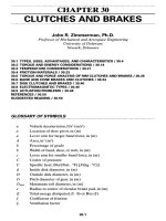
The
dynamic factor reflects
the
effect
of
inaccuracies
in
tooth
profile, tooth spac-
ing,
and
runout
on
instantaneous tooth loading.
For
gears manufactured
to
AGMA
class
11
tolerances
or
higher,
a
value
of 1.0 may be
used
for
dynamic factor. Curve
2
in
Fig. 34.18 gives
the
values
of
C
v
for
spiral bevels
and
hypoids
of
lower accuracy
or
for
large, planed spiral-bevel gears. Curve
3
gives
the
values
of
C
v
for
bevels
of
lower
accuracy
or for
large, planed straight-bevel gears.
Pitch
line
velocity
V,
ft/min
FIGURE
34.18
Dynamic
factors
K
v
and
C
v
.
The
load-distribution factor allows
for
misalignment
of the
gear
set
under oper-
ating
conditions. This factor
is
based
on the
magnitude
of the
displacements
of the
gear
and
pinion
from
their theoretical correct locations.
Use
Table
34.12
as a
guide
in
selecting
the
load-distribution factor.
The
surface-condition
factor
depends
on
surface
finish
as
affected
by
cutting, lap-
ping,
and
grinding.
It
also depends
on
surface treatment such
as
lubrizing.
And
C/can
be
taken
as 1.0
provided good gear
manufacturing
practices
are
followed.
Use
Table
34.13
to
locate
the
charts
for the two
geometry factors
/ and /.
The
geometry factor
for
durability
7
takes into consideration
the
relative radius
of
curvature between mating tooth surfaces, load location, load sharing,
effective
face
width,
and
inertia factor.
The
geometry factor
for
strength
/
takes into consideration
the
tooth form factor,
load location, load distribution,
effective
face
width, stress correction factor,
and
inertia factor.
TABLE
34.11
Overload Factors
K
0
,
C
0
f
Character
of
load
on
driven member
Prime
mover Uniform Medium shock Heavy shock
Uniform
1.00 1.25 1.75
Medium shock
1.25 1.50 2.00
Heavy
shock
1.50 1.75 2.25
fThis
table
is for
speed-decreasing
drive;
for
speed-increasing
drives
add
0.01
(Ay«)
2
to the
above
factors.
Dynamic
factor
TABLE
34.12
Load-Distribution Factors
K
m
C
m
Both
members
One
member
Neither
member
Application
straddle-mounted
straddle-mounted
straddle-mounted
General
industrial 1.00-1.10 1.10-1.25 1.25-1.40
Automotive
1.00-1.10 1.10-1.25
Aircraft
1.00-1.25 1.10-1.40 1.25-1.50
TABLE
34.13
Location
of
Geometry Factors
Figure
no.
Gear type Pressure angle,
(j)
Shaft
angle,
Z
Helix angle,
\j/
/
Factor
/
Factor
Straight bevel
20° 90° 0°
34.19
34.20
25°
90° 0°
34.21
34.22
Spiral bevel
20° 90° 35°
34.23 34.24
20°
90° 25°
34.25 34.26
20°
90° 15°
34.27 34.28
25°
90° 35°
34.29 34.30
20°
60° 35°
34.31
34.32
20°
120°
35°
34.33 34.34
20
ot
90° 35°
34.35 34.36
Hypoid
19° EID =
OAO
34.37 34.38
19°
EID
=
0.15 34.39 34.40
19°
EID
-0.20
34.41
34.42
22/2°
EID =
0.10 34.43 34.44
22/2°
EfD
=
0.15
34.45 34.46
22
1
^
0
EID
=
0.20 34.47 34.48
f
Automotive applications.
Interpolation between charts
may be
necessary
for
both
the / and /
factors.
34.6.3
Allowable
Stresses
The
maximum allowable stresses
are
based
on the
properties
of the
material. They
vary
with
the
material, heat treatment,
and
surface treatment. Table 34.14 gives
nominal values
for
allowable contact stress
on
gear teeth
for
commonly used gear
materials
and
heat treatments. Table 34.15 gives nominal values
for
allowable
bending stress
in
gear teeth
for
commonly used gear materials
and
heat treat-
ments.
Carburized case-hardened gears require
a
core hardness
in the
range
of 260 to
350
H
8
(26 to 37
R
c
)
and a
total case depth
in the
range shown
by
Fig. 34.49.
The
calculated contact stress
S
c
times
a
safety
factor
should
be
less than
the
allowable
contact stress
S
ac
.
The
calculated bending stress
S
t
times
a
safety
factor
should
be
less than
the
allowable bending stress
S
at
.
Geometry
Factor
I
FIGURE 34.19 Geometry
factor
/
for
durability
of
straight-bevel gears with
20°
pressure
angle
and 90°
shaft
angle.
Geometry Factor
J
FIGURE 34.20 Geometry factor
/
for
strength
of
straight-bevel gears with
20°
pressure
angle
and 90°
shaft
angle.
Number
of
Teeth
in
Pinion
Number
of
Teeth
in
Gear
for
which Geometry Factor
is
Desired
Geometry
Factor
I
FIGURE 34.21
Geometry
factor
7
for
durability
of
straight-bevel gears with
25°
pres-
sure angle
and 90°
shaft
angle.
Geometry
Factor
J
FIGURE 34.22 Geometry
factor
/
for
strength
of
straight-bevel gears with
25°
pressure angle
and 90°
shaft
angle.
Number
of
Teeth
in
Pinion
Number
of
Teeth
in
Gear
for
which Geometry Factor
is
Desired
Geometry
Factor
I
FIGURE 34.23 Geometry
factor
/ for
durability
of
spiral-bevel gears with
20°
pressure
angle,
35°
spiral angle,
and 90°
shaft
angle.
Number
of
Teeth
in
Mate
Geometry Factor
J
FIGURE 34.24 Geometry factor
/ for
strength
of
spiral-bevel gears with
20°
pressure
angle,
35°
spiral angle,
and 90°
shaft
angle.
Number
of
Teeth
in
Gear
for
which Geometry Factor
is
Desired
Number
of
Teeth
in
Pinion
Geometry
Factor
I
FIGURE 34.25 Geometry
factor
7
for
durability
of
spiral-bevel gears with
20°
pressure
angle,
25°
spiral angle,
and 90°
shaft
angle.
Number
of
Teeth
in
Mate
Geometry
Factor
J
FIGURE 34.26 Geometry factor
J for
strength
of
spiral-bevel gears with
20°
pressure
angle,
25°
spiral angle,
and 90°
shaft
angle.
Number
of
Teeth
in
Pinion
Number
of
Teeth
in
Gear
for
which Geometry Factor
is
Desired
Geometry
Factor
I
FIGURE
34.27
Geometry factor
/ for
durability
of
spiral-bevel gears with
20°
pres-
sure angle,
15°
spiral angle,
and 90°
shaft
angle.
Number
of
Teeth
in
Mate
Geometry
Factor
J
FIGURE
34.28
Geometry factor
/ for
strength
of
spiral-bevel gears with
20°
pressure angle,
15°
spiral angle,
and 90°
shaft
angle.
Number
of
Teeth
in
Pinion
Number
of
Teeth
in
Gear
for
which Geometry Factor
is
Desired
Geometry
Factor
I
FIGURE 34.29 Geometry factor
/ for
durability
of
spiral-bevel gears with
25°
pres-
sure angle,
35°
spiral angle,
and 90°
shaft
angle.
Number
of
Teeth
in
Mate
Geometry
Factor
J
FIGURE 34.30 Geometry factor
/ for
strength
of
spiral-bevel gears with
25°
pressure angle,
35°
spiral angle,
and 90°
shaft
angle.
Number
of
Teeth
in
Pinion
Number
of
Teeth
in
Gear
for
which Geometry Factor
is
Desired
Geometry Factor
I
FIGURE 34.31 Geometry factor
/ for
durability
of
spiral-bevel gears with
20°
pressure
angle,
35°
spiral angle,
and 60°
shaft
angle.
Number
of
Teeth
in
Mate
Geometry
Factor
J
FIGURE 34.32 Geometry
factor
/
for
strength
of
spiral-bevel gears with
20°
pressure
angle,
35°
spiral angle,
and 60°
shaft
angle.
Number
of
Teeth
in
Pinion
Number
of
Teeth
in
Gear
for
which Geometry Factor
is
Desired
Number
of
Teeth
in
Gear
Geometry Factor
I
FIGURE 34.33 Geometry factor
/ for
durability
of
spiral-bevel gears with
20°
pressure
angle,
35°
spiral angle,
and
120°
shaft
angle.
Number
of
Teeth
in
Mate
Geometry
Factor
J
FIGURE 34.34 Geometry
factor
J for
strength
of
spiral-bevel gears with
20°
pressure
angle,
35°
spiral angle,
and
120°
shaft
angle.
Number
of
Teeth
in
Gear
Number
of
Teeth
in
Pinion
Number
of
Teeth
in
Gear
for
which Geometry Factor
is
Desired
Geometry Factor
I
FIGURE 34.35 Geometry factor
7
for
durability
of
automotive spiral-bevel gears with
20°
pressure
angle,
35°
spiral angle,
and 90°
shaft
angle.
34.6.4
Scoring
Resistance
Scoring
is a
temperature-related process
in
which
the
surfaces actually tend
to
weld
together.
The oil
film
breaks down,
and the
tooth surfaces roll
and
slide
on one
another, metal against metal. Friction between
the
surfaces causes heat which
reaches
the
melting point
of the
tooth material,
and
scoring results.
The
factors
which
could cause scoring
are the
sliding velocity, surface
finish,
and
load concen-
trations along with
the
lubricant temperature, viscosity,
and
application.
But see
also
Chap.
6. If you
follow
the
recommendations under Sec. 34.7.6
on
lubrication
and the
manufacturer
uses acceptable practices
in
processing
the
gears, then scoring should
not be a
problem.
Number
of
Teeth
in
Pinion
Number
of
Teeth
in
Gear
Geometry Factor
J
FIGURE 34.36 Geometry factor
/ for
strength
of
automotive spiral-bevel gears with
20°
pressure
angle,
35°
spiral angle,
and 90°
shaft angle.
Number
of
Teeth
in
Mate
Geometry
Factor
I
FIGURE
34.37
Geometry
factor
/
for
hypoid gears with
19°
average pressure angle
and
EID
ratio
of
0.10.
Gear
Geometry Factor
JG
Pinion
Geometry Factor
Jp'
FIGURE
34.38
Geometry
factor
/
for
strength
of
hypoid gears with
19°
average pressure angle
and
EID
ratio
of
0.10.
Number
of
Pinion Teeth,
n
Number
of
Pinion
Teeth,
n
Geometry
Factor
I
FIGURE 34.39 Geometry
factor
7
for
durability
of
hypoid
gears with
19°
average
pressure
angle
and
EID
ratio
of
0.15.
Gear
Geometry Factor
JG
Pinion
Geometry Factor
Jp'
FIGURE 34.40 Geometry
factor
/ for
strength
of
hypoid gears with
19°
average pressure angle
and
EID
ratio
of
0.15.
Number
of
Pinion
Teeth,
n
Number
of
Pinion Teeth,
n
Geometry Factor
I
FIGURE 34.41 Geometry factor
/ for
durability
of
hypoid gears with
19°
average pressure angle
and EID
ratio
of
0.20.
Gear Geometry Factor
JG
Pinion
Geometry Factor
Jp'
FIGURE 34.42 Geometry factor
/
for
strength
of
hypoid gears with
19°
average pressure angle
and
EID
ratio
of
0.20.
Number
of
Pinion
Teeth,
n
Number
of
Pinion
Teeth,
n
Geometry Factor
I
FIGURE 34.43 Geometry factor
7
for
durability
of
hypoid gears with
22
1
^
0
average pressure angle
and EID
ratio
of
0.10.
Gear Geometry
Factor
JG
Pinion
Geometry
Factor
Jp'
FIGURE
34.44 Geometry
factor
/ for
strength
of
hypoid gears with
22M>°
average pressure angle
and
EID
ratio
of
0.10.
Number
of
Pinion
Teeth,
n
Number
of
Pinion Teeth,
n
Geometry
Factor
I
FIGURE 34.45 Geometry factor
/ for
durability
of
hypoid gears with
22
1
^
0
average pressure angle
and EID
ratio
of
0.15.
Gear
Geometry Factor
JG
Pinion
Geometry Factor
Jp'
FIGURE 34.46 Geometry
factor
/
for
strength
of
hypoid gears with
22
1
^
0
average pressure angle
and
EID
ratio
of
0.15.
Number
of
Gear Teeth,
N
Number
of
Pinion Teeth,
n
Number
of
Pinion Teeth,
n
Geometry Factor
I
FIGURE 34.47 Geometry factor
/ for
durability
of
hypoid gears with
22M>°
average pressure angle
and
EID
ratio
of
0.20.
Gear Geometry
Factor
JG
Pinion Geometry Factor
Jp'
FIGURE 34.48 Geometry
factor
/
for
strength
of
hypoid gears with
22i^°
average pressure angle
and
EID
ratio
of
0.20.
Number
of
Gear Teeth,
N
Number
of
Pinion Teeth,
n
Number
of
Pinion Teeth,
n
Number
of
Gear Teeth
Read
Up
Number
of
Gear Teeth
Read Down