Tài liệu The PIC Microcontroller pdf
Bạn đang xem bản rút gọn của tài liệu. Xem và tải ngay bản đầy đủ của tài liệu tại đây (2.3 MB, 187 trang )
The PIC Microcontroller
PIC book
Previous page Table of contents Chapter overview Next page
PIC microcontrollers for beginners,too!
Author: Nebojsa Matic
Paperback - 252 pages (May 15, 2000)
Dimensions (in inches): 0.62 x 9.13 x 7.28
PIC microcontrollers; low-cost computers-in-a-chip; allows
electronics designers and hobbyists add intelligence and
functions that mimic big computers for almost any electronic
product or project.
The purpose of this book is not to make a microcontroller expert
out of you, but to make you equal to those who had someone to
go to for their answers.
In this book you can find:
Practical connection samples for
Relays, Optocouplers, LCD's, Keys, Digits, A to D Converters, Serial communication etc.
Introduction to microcontrollers
Learn what they are, how they work, and how they can be helpful in your work.
Assembler language programming
How to write your first program, use of macros, addressing modes
Instruction Set
Description, sample and purpose for using each instruction
MPLAB program package
How to install it, how to start the first program, following the program step by step in the simulator
C o n t e n t s
CHAPTER I INTRODUCTION TO MICROCONTROLLERS
Introduction
History
Microcontrollers versus microprocessors
1.1 Memory unit
1.2 Central processing unit
1.3 Buses
1.4 Input-output unit
1.5 Serial communication
1.6 Timer unit
1.7 Watchdog
(1 of 5) [4/2/2003 16:17:25]
PIC book
1.8 Analog to digital converter
1.9 Program
CHAPTER II MICROCONTROLLER PIC16F84
Introduction
CISC, RISC
Applications
Clock/instruction cycle
Pipelining
Pin description
2.1 Clock generator - oscillator
2.2 Reset
2.3 Central processing unit
2.4 Ports
2.5 Memory organization
2.6 Interrupts
2.7 Free timer TMR0
2.8 EEPROM Data memory
CHAPTER III INSTRUCTION SET
Introduction
Instruction set in PIC16Cxx microcontroller family
Data Transfer
Arithmetic and logic
Bit operations
Directing the program flow
Instruction execution period
Word list
CHAPTER IV ASSEMBLY LANGUAGE PROGRAMMING
Introduction
Sample of a written program
Control directives
● 4.1 define
● 4.2 include
● 4.3 constant
● 4.4 variable
● 4.5 set
● 4.6 equ
(2 of 5) [4/2/2003 16:17:25]
PIC book
● 4.7 org
● 4.8 end
Conditional instructions
● 4.9 if
● 4.10 else
● 4.11 endif
● 4.12 while
● 4.13 endw
● 4.14 ifdef
● 4.15 ifndef
Data directives
● 4.16 cblock
● 4.17 endc
● 4.18 db
● 4.19 de
● 4.20 dt
Configurating a directive
● 4.21 _CONFIG
● 4.22 Processor
Assembler arithmetic operators
Files created as a result of program translation
Macros
CHAPTER V MPLAB
Introduction
5.1 Installing the MPLAB program package
5.2 Introduction to MPLAB
5.3 Choosing the development mode
5.4 Designing a project
5.5 Designing new assembler file
5.6 Writing a program
5.7 MPSIM simulator
5.8 Toolbar
CHAPTER VI THE SAMPLES
Introduction
6.1 The microcontroller power supply
6.2 Macros used in programs
(3 of 5) [4/2/2003 16:17:25]
PIC book
● Macros WAIT, WAITX
● Macro PRINT
6.3 Samples
● Light Emitting Diodes
● Keyboard
● Optocoupler
❍ Optocouplering the input lines
❍ Optocouplering the output lines
● Relays
● Generating a sound
● Shift registers
❍ Input shift register
❍ Output shift register
● 7-segment Displays (multiplexing)
● LCD display
● 12-bit AD converter
● Serial communication
APPENDIX A INSTRUCTION SET
APPENDIX B NUMERIC SYSTEMS
Introduction
B.1 Decimal numeric system
B.2 Binary numeric system
B.3 Hexadecimal numeric system
APPENDIX C GLOSSARY
(4 of 5) [4/2/2003 16:17:25]
PIC book
Subject :
Name :
State :
E-mail :
Your message:
Send us a comment about a
book
© C o p y r i g h t 2 0 0 1. m i k r o E l e k t r o n i k a. All Rights Reserved. For any comments contact webmaster.
(5 of 5) [4/2/2003 16:17:25]
Cooment about book PIC microcontrollers
USA
Submit
Reset
Chapter 1 - Introduction to Microprocessors
Previous page Table of contents Chapter overview Next page
CHAPTER 1
Introduction to Microcontrollers
Introduction
History
Microcontrollers versus microprocessors
1.1 Memory unit
1.2 Central processing unit
1.3 Buses
1.4 Input-output unit
1.5 Serial communication
1.6 Timer unit
1.7 Watchdog
1.8 Analog to digital converter
1.9 Program
Introduction
Circumstances that we find ourselves in today in the field of microcontrollers had their
beginnings in the development of technology of integrated circuits. This development has made
it possible to store hundreds of thousands of transistors into one chip. That was a prerequisite
for production of microprocessors , and the first computers were made by adding external
peripherals such as memory, input-output lines, timers and other. Further increasing of the
volume of the package resulted in creation of integrated circuits. These integrated circuits
contained both processor and peripherals. That is how the first chip containing a microcomputer
, or what would later be known as a microcontroller came about.
History
It was year 1969, and a team of Japanese engineers from the BUSICOM company arrived to
United States with a request that a few integrated circuits for calculators be made using their
projects. The proposition was set to INTEL, and Marcian Hoff was responsible for the project.
Since he was the one who has had experience in working with a computer (PC) PDP8, it occured
to him to suggest a fundamentally different solution instead of the suggested construction. This
solution presumed that the function of the integrated circuit is determined by a program stored
in it. That meant that configuration would be more simple, but that it would require far more
memory than the project that was proposed by Japanese engineers would require. After a
while, though Japanese engineers tried finding an easier solution, Marcian's idea won, and the
first microprocessor was born. In transforming an idea into a ready made product , Frederico
Faggin was a major help to INTEL. He transferred to INTEL, and in only 9 months had
succeeded in making a product from its first conception. INTEL obtained the rights to sell this
integral block in 1971. First, they bought the license from the BUSICOM company who had no
(1 of 9) [4/2/2003 16:17:33]
Chapter 1 - Introduction to Microprocessors
idea what treasure they had. During that year, there appeared on the market a microprocessor
called 4004. That was the first 4-bit microprocessor with the speed of 6 000 operations per
second. Not long after that, American company CTC requested from INTEL and Texas
Instruments to make an 8-bit microprocessor for use in terminals. Even though CTC gave up
this idea in the end, Intel and Texas Instruments kept working on the microprocessor and in
April of 1972, first 8-bit microprocessor appeard on the market under a name 8008. It was able
to address 16Kb of memory, and it had 45 instructions and the speed of 300 000 operations per
second. That microprocessor was the predecessor of all today's microprocessors. Intel kept
their developments up in April of 1974, and they put on the market the 8-bit processor under a
name 8080 which was able to address 64Kb of memory, and which had 75 instructions, and the
price began at $360.
In another American company Motorola, they realized quickly what was happening, so they put
out on the market an 8-bit microprocessor 6800. Chief constructor was Chuck Peddle, and
along with the processor itself, Motorola was the first company to make other peripherals such
as 6820 and 6850. At that time many companies recognized greater importance of
microprocessors and began their own developments. Chuck Peddle leaved Motorola to join MOS
Technology and kept working intensively on developing microprocessors.
At the WESCON exhibit in United States in 1975, a critical event took place in the history of
microprocessors. The MOS Technology announced it was marketing microprocessors 6501 and
6502 at $25 each, which buyers could purchase immediately. This was so sensational that
many thought it was some kind of a scam, considering that competitors were selling 8080 and
6800 at $179 each. As an answer to its competitor, both Intel and Motorola lowered their prices
on the first day of the exhibit down to $69.95 per microprocessor. Motorola quickly brought suit
against MOS Technology and Chuck Peddle for copying the protected 6800. MOS Technology
stopped making 6501, but kept producing 6502. The 6502 was a 8-bit microprocessor with 56
instructions and a capability of directly addressing 64Kb of memory. Due to low cost , 6502
becomes very popular, so it was installed into computers such as: KIM-1, Apple I, Apple II,
Atari, Comodore, Acorn, Oric, Galeb, Orao, Ultra, and many others. Soon appeared several
makers of 6502 (Rockwell, Sznertek, GTE, NCR, Ricoh, and Comodore takes over MOS
Technology) which was at the time of its prosperity sold at a rate of 15 million processors a
year!
Others were not giving up though. Frederico Faggin leaves Intel, and starts his own Zilog Inc.
In 1976 Zilog announced the Z80. During the making of this microprocessor, Faggin made a
pivotal decision. Knowing that a great deal of programs have been already developed for 8080,
Faggin realized that many would stay faithful to that microprocessor because of great
expenditure which redoing of all of the programs would result in. Thus he decided that a new
processor had to be compatible with 8080, or that it had to be capable of performing all of the
programs which had already been written for 8080. Beside these characteristics, many new
ones have been added, so that Z80 was a very powerful microprocessor in its time. It was able
to address directly 64 Kb of memory, it had 176 instructions, a large number of registers, a
built in option for refreshing the dynamic RAM memory, single-supply, greater speed of work
etc. Z80 was a great success and everybody converted from 8080 to Z80. It could be said that
Z80 was without a doubt commercially most successful 8-bit microprocessor of that time.
Besides Zilog, other new manufacturers like Mostek, NEC, SHARP, and SGS also appeared. Z80
was the heart of many computers like Spectrum, Partner, TRS703, Z-3 .
In 1976, Intel came up with an improved version of 8-bit microprocessor named 8085.
However, Z80 was so much better that Intel soon lost the battle. Altough a few more
processors appeared on the market (6809, 2650, SC/MP etc.), everything was actually already
decided. There weren't any more great improvements to make manufacturers convert to
something new, so 6502 and Z80 along with 6800 remained as main representatives of the 8-
bit microprocessors of that time.
Microcontrollers versus Microprocessors
Microcontroller differs from a microprocessor in many ways. First and the most important is its
functionality. In order for a microprocessor to be used, other components such as memory, or
(2 of 9) [4/2/2003 16:17:33]
Chapter 1 - Introduction to Microprocessors
components for receiving and sending data must be added to it. In short that means that
microprocessor is the very heart of the computer. On the other hand, microcontroller is
designed to be all of that in one. No other external components are needed for its application
because all necessary peripherals are already built into it. Thus, we save the time and space
needed to construct devices.
1.1 Memory unit
Memory is part of the microcontroller whose function is to store data.
The easiest way to explain it is to describe it as one big closet with lots of drawers. If we
suppose that we marked the drawers in such a way that they can not be confused, any of their
contents will then be easily accessible. It is enough to know the designation of the drawer and
so its contents will be known to us for sure.
Memory components are exactly like that. For a certain input we get the contents of a certain
addressed memory location and that's all. Two new concepts are brought to us: addressing and
memory location. Memory consists of all memory locations, and addressing is nothing but
selecting one of them. This means that we need to select the desired memory location on one
hand, and on the other hand we need to wait for the contents of that location. Beside reading
from a memory location, memory must also provide for writing onto it. This is done by
supplying an additional line called control line. We will designate this line as R/W (read/write).
Control line is used in the following way: if r/w=1, reading is done, and if opposite is true then
writing is done on the memory location. Memory is the first element, and we need a few
operation of our microcontroller .
1.2 Central Processing Unit
Let add 3 more memory locations to a specific block that will have a built in capability to
multiply, divide, subtract, and move its contents from one memory location onto another. The
part we just added in is called "central processing unit" (CPU). Its memory locations are called
registers.
(3 of 9) [4/2/2003 16:17:33]
Chapter 1 - Introduction to Microprocessors
Registers are therefore memory locations whose role is to help with performing various
mathematical operations or any other operations with data wherever data can be found. Look at
the current situation. We have two independent entities (memory and CPU) which are
interconnected, and thus any exchange of data is hindered, as well as its functionality. If, for
example, we wish to add the contents of two memory locations and return the result again back
to memory, we would need a connection between memory and CPU. Simply stated, we must
have some "way" through data goes from one block to another.
1.3 Bus
That "way" is called "bus". Physically, it represents a group of 8, 16, or more wires
There are two types of buses: address and data bus. The first one consists of as many lines as
the amount of memory we wish to address, and the other one is as wide as data, in our case 8
bits or the connection line. First one serves to transmit address from CPU memory, and the
second to connect all blocks inside the microcontroller.
As far as functionality, the situation has improved, but a new problem has also appeared: we
have a unit that's capable of working by itself, but which does not have any contact with the
outside world, or with us! In order to remove this deficiency, let's add a block which contains
several memory locations whose one end is connected to the data bus, and the other has
connection with the output lines on the microcontroller which can be seen as pins on the
electronic component.
(4 of 9) [4/2/2003 16:17:33]
Chapter 1 - Introduction to Microprocessors
1.4 Input-output unit
Those locations we've just added are called "ports". There are several types of ports : input,
output or bidiectional ports. When working with ports, first of all it is necessary to choose which
port we need to work with, and then to send data to, or take it from the port.
When working with it the port acts like a memory location. Something is simply being written
into or read from it, and it could be noticed on the pins of the microcontroller.
1.5 Serial communication
Beside stated above we've added to the already existing unit the possibility of communication
with an outside world. However, this way of communicating has its drawbacks. One of the basic
drawbacks is the number of lines which need to be used in order to transfer data. What if it is
being transferred to a distance of several kilometers? The number of lines times number of
kilometers doesn't promise the economy of the project. It leaves us having to reduce the
number of lines in such a way that we don't lessen its functionality. Suppose we are working
with three lines only, and that one line is used for sending data, other for receiving, and the
third one is used as a reference line for both the input and the output side. In order for this to
work, we need to set the rules of exchange of data. These rules are called protocol. Protocol is
therefore defined in advance so there wouldn't be any misunderstanding between the sides that
are communicating with each other. For example, if one man is speaking in French, and the
other in English, it is highly unlikely that they will quickly and effectively understand each other.
Let's suppose we have the following protocol. The logical unit "1" is set up on the transmitting
line until transfer begins. Once the transfer starts, we lower the transmission line to logical "0"
for a period of time (which we will designate as T), so the receiving side will know that it is
receiving data, and so it will activate its mechanism for reception. Let's go back now to the
transmission side and start putting logic zeros and ones onto the transmitter line in the order
from a bit of the lowest value to a bit of the highest value. Let each bit stay on line for a time
period which is equal to T, and in the end, or after the 8th bit, let us bring the logical unit "1"
back on the line which will mark the end of the transmission of one data. The protocol we've
just described is called in professional literature NRZ (Non-Return to Zero).
(5 of 9) [4/2/2003 16:17:33]
Chapter 1 - Introduction to Microprocessors
As we have separate lines for receiving and sending, it is possible to receive and send data
(info.) at the same time. So called full-duplex mode block which enables this way of
communication is called a serial communication block. Unlike the parallel transmission, data
moves here bit by bit, or in a series of bits what defines the term serial communication comes
from. After the reception of data we need to read it from the receiving location and store it in
memory as opposed to sending where the process is reversed. Data goes from memory through
the bus to the sending location, and then to the receiving unit according to the protocol.
1.6 Timer unit
Since we have the serial communication explained, we can receive, send and process data.
However, in order to utilize it in industry we need a few additionally blocks. One of those is the
timer block which is significant to us because it can give us information about time, duration,
protocol etc. The basic unit of the timer is a free-run counter which is in fact a register whose
numeric value increments by one in even intervals, so that by taking its value during periods T1
and T2 and on the basis of their difference we can determine how much time has elapsed. This
is a very important part of the microcontroller whose understnding requires most of our time.
1.7 Watchdog
One more thing is requiring our attention is a flawless functioning of the microcontroller
during its run-time. Suppose that as a result of some interference (which often does occur in
industry) our microcontroller stops executing the program, or worse, it starts working
incorrectly.
(6 of 9) [4/2/2003 16:17:33]
Chapter 1 - Introduction to Microprocessors
Of course, when this happens with a computer, we simply reset it and it will keep working.
However, there is no reset button we can push on the microcontroller and thus solve our
problem. To overcome this obstacle, we need to introduce one more block called watchdog. This
block is in fact another free-run counter where our program needs to write a zero in every time
it executes correctly. In case that program gets "stuck", zero will not be written in, and counter
alone will reset the microcontroller upon achieving its maximum value. This will result in
executing the program again, and correctly this time around. That is an important element of
every program to be reliable without man's supervision.
1.8 Analog to Digital Converter
As the peripheral signals usually are substantially different from the ones that microcontroller
can understand (zero and one), they have to be converted into a pattern which can be
comprehended by a microcontroller. This task is performed by a block for analog to digital
conversion or by an ADC. This block is responsible for converting an information about some
analog value to a binary number and for follow it through to a CPU block so that CPU block can
further process it.
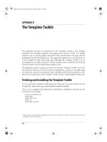
Finnaly, the microcontroller is now completed, and all we need to do now is to assemble it into
an electronic component where it will access inner blocks through the outside pins. The picture
below shows what a microcontroller looks like inside.
Physical configuration of the interior of a microcontroller
Thin lines which lead from the center towards the sides of the microcontroller represent wires
connecting inner blocks with the pins on the housing of the microcontroller so called bonding
lines. Chart on the following page represents the center section of a microcontroller.
(7 of 9) [4/2/2003 16:17:33]
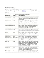
Chapter 1 - Introduction to Microprocessors
Microcontroller outline with its basic elements and internal connections
For a real application, a microcontroller alone is not enough. Beside a microcontroller, we need
a program that would be executed, and a few more elements which make up a interface logic
towards the elements of regulation (which will be discussed in later chapters).
1.9 Program
Program writing is a special field of work with microcontrollers and is called "programming". Try
to write a small program in a language that we will make up ourselves first and then would be
understood by anyone.
START
REGISTER1=MEMORY LOCATION_A
REGISTER2=MEMORY LOCATION_B
PORTA=REGISTER1 + REGISTER2
END
(8 of 9) [4/2/2003 16:17:33]
Chapter 1 - Introduction to Microprocessors
The program adds the contents of two memory locations, and views their sum on port A. The
first line of the program stands for moving the contents of memory location "A" into one of the
registers of central processing unit. As we need the other data as well, we will also move it into
the other register of the central processing unit. The next instruction instructs the central
processing unit to add the contents of those two registers and send a result to port A, so that
sum of that addition would be visible to the outside world. For a more complex problem,
program that works on its solution will be bigger.
Programming can be done in several languages such as Assembler, C and Basic which are most
commonly used languages. Assembler belongs to lower level languages that are programmed
slowly, but take up the least amount of space in memory and gives the best results where the
speed of program execution is concerned. As it is the most commonly used language in
programming microcontrollers it will be discussed in a later chapter. Programs in C language
are easier to be written, easier to be understood, but are slower in executing from assembler
programs. Basic is the easiest one to learn, and its instructions are nearest a man's way of
reasoning, but like C programming language it is also slower than assembler. In any case,
before you make up your mind about one of these languages you need to consider carefully the
demands for execution speed, for the size of memory and for the amount of time available for
its assembly.
After the program is written, we would install the microcontroller into a device and run it. In
order to do this we need to add a few more external components necessary for its work. First
we must give life to a microcontroller by connecting it to a power supply (power needed for
operation of all electronic instruments) and oscillator whose role is similar to the role that heart
plays in a human body. Based on its clocks microcontroller executes instructions of a program.
As it receives supply microcontroller will perform a small check up on itself, look up the
beginning of the program and start executing it. How the device will work depends on many
parameters, the most important of which is the skillfulness of the developer of hardware, and
on programmer's expertise in getting the maximum out of the device with his program.
Previous page Table of contents Chapter overview Next page
© Copyright 1999. mikroElektronika. All Rights Reserved. For any comments contact webmaster.
(9 of 9) [4/2/2003 16:17:33]
Chapter 2 - Microcontroller PIC16F84
Previous page Table of contents Chapter overview Next page
CHAPTER 2
Microcontroller PIC16F84
Introduction
CISC, RISC
Applications
Clock/instruction cycle
Pipelining
Pin description
2.1 Clock generator - oscillator
2.2 Reset
2.3 Central processing unit
2.4 Ports
2.5 Memory organization
2.6 Interrupts
2.7 Free timer TMR0
2.8 EEPROM Data memory
Introduction
PIC16F84 belongs to a class of 8-bit microcontrollers of RISC architecture. Its general structure
is shown on the following map representing basic blocks.
Program memory (FLASH)- for storing a written program.
Since memory made in FLASH technology can be programmed and cleared more than once, it
makes this microcontroller suitable for device development.
EEPROM - data memory that needs to be saved when there is no supply.
It is usually used for storing important data that must not be lost if power supply suddenly stops.
For instance, one such data is an assigned temperature in temperature regulators. If during a loss
of power supply this data was lost, we would have to make the adjustment once again upon
return of supply. Thus our device looses on self-reliance.
RAM - data memory used by a program during its execution.
In RAM are stored all inter-results or temporary data during run-time.
PORTA and PORTB are physical connections between the microcontroller and the outside world.
Port A has five, and port B eight pins.
FREE-RUN TIMER is an 8-bit register inside a microcontroller that works independently of the
program. On every fourth clock of the oscillator it increments its value until it reaches the
maximum (255), and then it starts counting over again from zero. As we know the exact timing
between each two increments of the timer contents, timer can be used for measuring time which
is very useful with some devices.
CENTRAL PROCESSING UNIT has a role of connective element between other blocks in the
(1 of 5) [4/2/2003 16:17:37]
Chapter 2 - Microcontroller PIC16F84
microcontroller. It coordinates the work of other blocks and executes the user program.
CISC, RISC
It has already been said that PIC16F84 has a RISC architecture. This term is often found in
computer literature, and it needs to be explained here in more detail. Harvard architecture is a
newer concept than von-Neumann's. It rose out of the need to speed up the work of a
microcontroller. In Harvard architecture, data bus and address bus are separate. Thus a greater
flow of data is possible through the central processing unit, and of course, a greater speed of
work. Separating a program from data memory makes it further possible for instructions not to
have to be 8-bit words. PIC16F84 uses 14 bits for instructions which allows for all instructions to
be one word instructions. It is also typical for Harvard architecture to have fewer instructions than
von-Neumann's, and to have instructions usually executed in one cycle.
Microcontrollers with Harvard architecture are also called "RISC microcontrollers". RISC stands for
Reduced Instruction Set Computer. Microcontrollers with von-Neumann's architecture are called
'CISC microcontrollers'. Title CISC stands for Complex Instruction Set Computer.
Since PIC16F84 is a RISC microcontroller, that means that it has a reduced set of instructions,
(2 of 5) [4/2/2003 16:17:37]
Chapter 2 - Microcontroller PIC16F84
more precisely 35 instructions . (ex. Intel's and Motorola's microcontrollers have over hundred
instructions) All of these instructions are executed in one cycle except for jump and branch
instructions. According to what its maker says, PIC16F84 usually reaches results of 2:1 in code
compression and 4:1 in speed in relation to other 8-bit microcontrollers in its class.
Applications
PIC16F84 perfectly fits many uses, from automotive industries and controlling home appliances to
industrial instruments, remote sensors, electrical doorlocks and safety devices. It is also ideal for
smart cards as well as for battery supplied devices because of its low consumption.
EEPROM memory makes it easier to apply microcontrollers to devices where permanent storage of
various parameters is needed (codes for transmitters, motor speed, receiver frequencies, etc.).
Low cost, low consumption, easy handling and flexibility make PIC16F84 applicable even in areas
where microcontrollers had not previously been considered (example: timer functions, interface
replacement in larger systems, coprocessor applications, etc.).
In System Programmability of this chip (along with using only two pins in data transfer) makes
possible the flexibility of a product, after assembling and testing have been completed. This
capability can be used to create assembly-line production, to store calibration data available only
after final testing, or it can be used to improve programs on finished products.
Clock / instruction cycle
Clock is microcontroller's main starter, and is obtained from an external component called an
"oscillator". If we want to compare a microcontroller with a time clock, our "clock" would then be a
ticking sound we hear from the time clock. In that case, oscillator could be compared to a spring
that is wound so time clock can run. Also, force used to wind the time clock can be compared to
an electrical supply.
Clock from the oscillator enters a microcontroller via OSC1 pin where internal circuit of a
microcontroller divides the clock into four even clocks Q1, Q2, Q3, and Q4 which do not overlap.
These four clocks make up one instruction cycle (also called machine cycle) during which one
instruction is executed.
Execution of instruction starts by calling an instruction that is next in string. Instruction is called
from program memory on every Q1 and is written in instruction register on Q4. Decoding and
execution of instruction are done between the next Q1 and Q4 cycles. On the following diagram
we can see the relationship between instruction cycle and clock of the oscillator (OSC1) as well as
that of internal clocks Q1-Q4. Program counter (PC) holds information about the address of the
next instruction.
Pipelining
(3 of 5) [4/2/2003 16:17:37]
Chapter 2 - Microcontroller PIC16F84
Instruction cycle consists of cycles Q1, Q2, Q3 and Q4. Cycles of calling and executing instructions
are connected in such a way that in order to make a call, one instruction cycle is needed, and one
more is needed for decoding and execution. However, due to pipelining, each instruction is
effectively executed in one cycle. If instruction causes a change on program counter, and PC
doesn't point to the following but to some other address (which can be the case with jumps or
with calling subprograms), two cycles are needed for executing an instruction. This is so because
instruction must be processed again, but this time from the right address. Cycle of calling begins
with Q1 clock, by writing into instruction register (IR). Decoding and executing begins with Q2, Q3
and Q4 clocks.
TCY0 reads in instruction MOVLW 55h (it doesn't matter to us what instruction was executed,
because there is no rectangle pictured on the bottom).
TCY1 executes instruction MOVLW 55h and reads in MOVWF PORTB.
TCY2 executes MOVWF PORTB and reads in CALL SUB_1.
TCY3 executes a call of a subprogram CALL SUB_1, and reads in instruction BSF PORTA, BIT3. As
this instruction is not the one we need, or is not the first instruction of a subprogram SUB_1
whose execution is next in order, instruction must be read in again. This is a good example of an
instruction needing more than one cycle.
TCY4 instruction cycle is totally used up for reading in the first instruction from a subprogram at
address SUB_1.
TCY5 executes the first instruction from a subprogram SUB_1 and reads in the next one.
Pin description
PIC16F84 has a total of 18 pins. It is most frequently found in a DIP18 type of case but can also
be found in SMD case which is smaller from a DIP. DIP is an abbreviation for Dual In Package.
SMD is an abbreviation for Surface Mount Devices suggesting that holes for pins to go through
when mounting, aren't necessary in soldering this type of a component.
(4 of 5) [4/2/2003 16:17:37]
Chapter 2 - Microcontroller PIC16F84
Pins on PIC16F84 microcontroller have the following meaning:
Pin no.1 RA2 Second pin on port A. Has no additional function
Pin no.2 RA3 Third pin on port A. Has no additional function.
Pin no.3 RA4 Fourth pin on port A. TOCK1 which functions as a timer is also found on this pin
Pin no.4 MCLR Reset input and Vpp programming voltage of a microcontroller
Pin no.5 Vss Ground of power supply.
Pin no.6 RB0 Zero pin on port B. Interrupt input is an additional function.
Pin no.7 RB1 First pin on port B. No additional function.
Pin no.8 RB2 Second pin on port B. No additional function.
Pin no.9 RB3 Third pin on port B. No additional function.
Pin no.10 RB4 Fourth pin on port B. No additional function.
Pin no.11 RB5 Fifth pin on port B. No additional function.
Pin no.12 RB6 Sixth pin on port B. 'Clock' line in program mode.
Pin no.13 RB7 Seventh pin on port B. 'Data' line in program mode.
Pin no.14 Vdd Positive power supply pole.
Pin no.15 OSC2 Pin assigned for connecting with an oscillator
Pin no.16 OSC1 Pin assigned for connecting with an oscillator
Pin no.17 RA2 Second pin on port A. No additional function
Pin no.18 RA1 First pin on port A. No additional function.
Previous page Table of contents Chapter overview Next page
© Copyright 1999. mikroElektronika. All Rights Reserved. For any comments contact webmaster.
(5 of 5) [4/2/2003 16:17:37]
Chapter 2 - Microcontroller PIC16F84
Previous page Table of contents Chapter overview Next page
2.1 Clock generator - oscillator
Oscillator circuit is used for providing a microcontroller with a clock. Clock is needed so that
microcontroller could execute a program or program instructions.
Types of oscillators
PIC16F84 can work with four different configurations of an oscillator. Since configurations with
crystal oscillator and resistor-capacitor (RC) are the ones that are used most frequently, these are
the only ones we will mention here. Microcontroller type with a crystal oscillator has in its
designation XT, and a microcontroller with resistor-capacitor pair has a designation RC. This is
important because you need to mention the type of oscillator when buying a microcontroller.
XT Oscillator
Crystal oscillator is kept in metal housing
with two pins where you have written down
the frequency at which crystal oscillates. One
ceramic capacitor of 30pF whose other end is
connected to the ground needs to be
connected with each pin.
Oscillator and capacitors can be packed in
joint case with three pins. Such element is
called ceramic resonator and is represented
in charts like the one below. Center pins of
the element is the ground, while end pins are
connected with OSC1 and OSC2 pins on the
microcontroller. When designing a device,
the rule is to place an oscillator nearer a
microcontroller, so as to avoid any
interference on lines on which microcontroller
is receiving a clock.
RC Oscillator
In applications where great time precision is not necessary, RC oscillator offers additional savings
during purchase. Resonant frequency of RC oscillator depends on supply voltage rate, resistance
R, capacity C and working temperature. It should be mentioned here that resonant frequency is
also influenced by normal variations in process parameters, by tolerance of external R and C
components, etc.
(1 of 3) [4/2/2003 16:17:41]
Chapter 2 - Microcontroller PIC16F84
Above diagram shows how RC oscillator is connected with PIC16F84. With value of resistor R being
below 2.2k, oscillator can become unstable, or it can even stop the oscillation. With very high
value of R (ex.1M) oscillator becomes very sensitive to noise and humidity. It is recommended
that value of resistor R should be between 3 and 100k. Even though oscillator will work without an
external capacitor(C=0pF), capacitor above 20pF should still be used for noise and stability. No
matter which oscillator is being used, in order to get a clock that microcontroller works upon, a
clock of the oscillator must be divided by 4. Oscillator clock divided by 4 can also be obtained on
OSC2/CLKOUT pin, and can be used for testing or synchronizing other logical circuits.
Following a supply, oscillator starts oscillating. Oscillation at first has an unstable period and
amplitude, but after some period of time it becomes stabilized.
To prevent such inaccurate clock from influencing microcontroller's performance, we need to keep
the microcontroller in reset state during stabilization of oscillator's clock. Above diagram shows a
typical shape of a signal which microcontroller gets from the quartz oscillator following a supply.
(2 of 3) [4/2/2003 16:17:41]
Chapter 2 - Microcontroller PIC16F84
Previous page Table of contents Chapter overview Next page
© Copyright 1999. mikroElektronika. All Rights Reserved. For any comments contact webmaster.
(3 of 3) [4/2/2003 16:17:41]
Chapter 2 - Microcontroller PIC16F84
Previous page Table of contents Chapter overview Next page
2.2 Reset
Reset is used for putting the microcontroller into a 'known' condition. That practically means that
microcontroller can behave rather inaccurately under certain undesirable conditions. In order to
continue its proper functioning it has to be reset, meaning all registers would be placed in a
starting position. Reset is not only used when microcontroller doesn't behave the way we want it
to, but can also be used when trying out a device as an interrupt in program execution, or to get a
microcontroller ready when reading in a program.
In order to prevent from bringing a
logical zero to MCLR pin accidentally
(line above it means that reset is
activated by a logical zero), MCLR has
to be connected via resistor to the
positive supply pole. Resistor should be
between 5 and 10K. This kind of
resistor whose function is to keep a
certain line on a logical one as a
preventive, is called a pull up.
Microcontroller PIC16F84 knows several sources of resets:
a) Reset during power on, POR (Power-On Reset)
b) Reset during regular work by bringing logical zero to MCLR microcontroller's pin.
c) Reset during SLEEP regime
d) Reset at watchdog timer (WDT) overflow
e) Reset during at WDT overflow during SLEEP work regime.
The most important reset sources are a) and b). The first one occurs each time a power supply is
brought to the microcontroller and serves to bring all registers to a starting position initial state.
The second one is a product of purposeful bringing in of a logical zero to MCLR pin during normal
operation of the microcontroller. This second one is often used in program development.
During a reset, RAM memory locations are not being reset. They are unknown during a power up
and are not changed at any reset. Unlike these, SFR registers are reset to a starting position initial
state. One of the most important effects of a reset is setting a program counter (PC) to zero
(0000h) , which enables the program to start executing from the first written instruction.
Reset at supply voltage drop below the permissible (Brown-out
Reset)
Impulse for resetting during voltage voltage-up is generated by microcontroller itself when it
detects an increase in supply Vdd (in a range from 1.2V to 1.8V). That impulse lasts 72ms which
is enough time for an oscillator to get stabilized. These 72ms are provided by an internal PWRT
timer which has its own RC oscillator. Microcontroller is in a reset mode as long as PWRT is active.
However, as device is working, problem arises when supply doesn't drop to zero but falls below
the limit that guarantees microcontroller's proper functioning. This is a likely case in practice,
(1 of 2) [4/2/2003 16:17:42]
Chapter 2 - Microcontroller PIC16F84
especially in industrial environment where disturbances and instability of supply are an everyday
occurrence. To solve this problem we need to make sure that microcontroller is in a reset state
each time supply falls below the approved limit.
If, according to electrical specification, internal reset circuit of a microcontroller can not satisfy the
needs, special electronic components can be used which are capable of generating the desired
reset signal. Beside this function, they can also function in watching over supply voltage. If
voltage drops below specified level, a logical zero would appear on MCLR pin which holds the
microcontroller in reset state until voltage is not within limits that guarantee correct functioning.
Previous page Table of contents Chapter overview Next page
© Copyright 1999. mikroElektronika. All Rights Reserved. For any comments contact webmaster.
(2 of 2) [4/2/2003 16:17:42]