Tài liệu Recommended Practice for Soft Ground Site Characterization: Arthur Casagrande Lecture pptx
Bạn đang xem bản rút gọn của tài liệu. Xem và tải ngay bản đầy đủ của tài liệu tại đây (1.2 MB, 60 trang )
Recommended Practice for Soft Ground Site Characterization:
Arthur Casagrande Lecture
Práctica Recomendada para la Caracterización de Sitios en
Terreno Blando: Conferencia Arthur Casagrande
by
Charles C. Ladd, Hon. M., ASCE
Edmund K. Turner Professor Emeritus
Department of Civil and Environmental Engineering,
Massachusetts Institute of Technology, Cambridge, MA, USA
and
Don J. DeGroot, M., ASCE
Associate Professor
Department of Civil and Environmental Engineering,
University of Massachusetts Amherst, Amherst, MA, USA
prepared for
12
th
Panamerican Conference on Soil Mechanics and Geotechnical Engineering
Massachusetts Institute of Technology
Cambridge, MA USA
June 22 – 25, 2003
April 10, 2003
Revised: May 9, 2004
ii
Table of Contents
List of Tables iii
List of Figures iv
ABSTRACT 1
1. INTRODUCTION 2
2. GENERAL METHODOLOGY 4
3. SOIL STRATIGRAPHY, SOIL CLASSIFICATION AND
GROUND WATER CONDITIONS 5
4. UNDISTURBED SAMPLING & SAMPLE DISTURBANCE 6
4.1 Sources of Disturbance and Procedures to Minimize 6
4.2 Radiography 10
4.3 Assessing Sample Quality 10
5. IN SITU TESTING 14
5.1 Field Vane Test 14
5.2 Piezocone Test 16
5.3 Principal Recommendations 22
6. LABORATORY CONSOLIDATION TESTING 23
6.1 Fundamentals 23
6.2 Compression Curves 24
6.3 Flow Characteristics 27
6.4 Principal Recommendations 27
7. UNDRAINED SHEAR BEHAVIOR AND STABILITY ANALYSES 29
7.1 Review of Behavioral Fundamentals 29
7.2 Problems with Conventional UUC and CIUC Tests 34
7.3 Strength Testing for Undrained Stability Analyses 35
7.4 Three Dimensional End Effects 39
7.5 Principal Recommendations 39
8. LABORATORY CONSOLIDATED-UNDRAINED SHEAR TESTING 40
8.1 Experimental Capabilities and Testing Procedures 40
8.2 Reconsolidation Procedure 42
8.3 Interpretation of Strength Data 46
8.4 Principal Recommendations 50
9. SUMMARY AND CONCLUSIONS 51
10. ACKNOWLEDGMENTS 52
REFERENCES 53
iii
List of Tables
Table 1.1 Clay Properties for Soft Ground Construction 3
Table 2.2 Pros and Cons of In Situ vs. Laboratory Testing for Soil Profiling and
Engineering Properties 4
Table 3.1 Atterberg Limits for Soft Bangkok Clay 6
Table 7.1 Levels of Sophistication for Evaluating Undrained Stability 35
Table 7.2 Level C Values of S and m for Estimating s
u
(ave) via SHANSEP Equation
(slightly modified from Section 5.3 of Ladd 1991) 36
Table 8.1 Effect of Consolidation Time on NC s
u
/σ'
vc
from CK
0
UDSS Tests 43
Table 8.2 SHANSEP Design Parameters for Sergipe Clay (Ladd and Lee 1993) 49
List of Figures
Figure 3.1 Soil Behavior Type Classification Chart Based on Normalized CPT/CPTU
Data (after Robertson 1990, Lunne et al. 1997b) 5
Figure 4.1 Hypothetical Stress Path During Tube Sampling and Specimen Preparation of
Centerline Element of Low OCR Clay (after Ladd and Lambe 1963,
Baligh et al. 1987) 7
Figure 4.2 Effect of Drilling Mud Weight and Depth to Water Table on Borehole Stability
for OCR = 1 Clays 8
Figure 4.3 MIT Procedure for Obtaining Test Specimen from Tube Sample (Germaine 2003) 9
Figure 4.4 Results of Radiography and s
u
Index Tests on Deep Tube Sample of Offshore
Orinoco Clay (from Ladd et al. 1980) 11
Figure 4.5 Results of Oedometer Tests on Deep Tube Sample of Offshore Orinoco Clay
(from Ladd et al. 1980) 12
Figure 4.6 (a) Specimen Quality Designation and (b) Stress History for Boston Blue Clay
At CA/T South Boston (after Ladd et al. 1999 and Haley and Aldrich 1993) 13
Figure 4.7 Effects of Sample Disturbance on CR
max
from Oedometer Tests (LIR = 1) on
Highly Plastic Organic Clay (numbers are negative elevation (m) for OCR ≥ 1;
GS El. = + 2m) 13
Figure 5.1 Field Vane Correction Factor vs. Plasticity Index Derived from Embankment
Failures (after Ladd et al. 1977) 15
Figure 5.2 Field Vane Undrained Strength Ratio at OCR = 1 vs. Plasticity Index for
Homogeneous Clays (no shells or sand) [data points from Lacasse et al. 1978
and Jamiolkowski et al. 1985] 15
Figure 5.3 Location Plan of Bridge Abutments with Preload Fill and Preconstruction
Borings and In Situ Tests 16
Figure 5.4 Depth vs. Atterberg Limits, Measured s
u
(FV) and Stress History for Highway
Project in Northern Ontario 17
Figure 5.5 Revised Stress History with σ'
p
(FV) and MIT Lab Tests 17
Figure 5.6 Illustration of Piezocone (CPTU) with Area = 10 cm
2
(adapted from ASTM
D5778 and Lunne et al. 1997b) 17
Figure 5.7 Example of Very Low Penetration Pore Pressure from CPTU Sounding for I-15
Reconstruction, Salt Lake City (record provide by Steven Saye) 18
iv
Figure 5.8 Comparison of Stress History and CPTU Cone Factor for Boston Blue Clay at
CA/T South Boston and MIT Bldg 68: Reference s
u
(DSS) from SHANSEP
CK
0
UDSS Tests (after Ladd et al. 1999 and Berman et al. 1993) 19
Figure 5.9 Comparison of CPTU Normalized Net Cone Resistance vs. OCR for BBC at
South Boston and MIT Bldg 68 20
Figure 5.10 Cross-Section of TPS Breakwater Showing Initial Failure, Redesign, and
Instrumentation at QM2 20
Figure 5.11 TPS Location Plan (Adapted from Geoprojetos, Ltda.) 21
Figure 5.12 Atterberg Limits and Stress History of Sergipe Clay (Ladd and Lee 1993) 22
Figure 5.13 Selected Stress History of Sergipe Clay Using CPTU Data from B2 – B5
Soundings (Ladd and Lee 1993) 22
Figure 6.1 Fundamentals of 1-D Consolidation Behavior: Compression Curve, Hydraulic
Conductivity, Coefficient of Consolidation and Secondary Compression vs.
Normalized Vertical Effective Stress 24
Figure 6.2 Comparison of Compression Curves from CRS and IL Tests on Sherbrooke
Block Samples (CRS tests run with ∆ε/∆t = 1%/hr): (a) Gloucester Clay,
Ottawa, Canada; (b) Boston Blue Clay, Newbury, MA 26
Figure 6.3 Vertical Strain – Time Curves for Increments Spanning σ'
p
from the IL Test on
BBC Plotted in Fig. 6.2b 26
Figure 6.4 Estimation of Preconsolidation Stress Using the Strain Energy Method
(after Becker et al. 1987) 27
Figure 6.5 Results of CRS Test on Structured CH Lacustrine Clay, Northern Ontario,
Canada (z = 15.7 m, w
n
= 72%, Est. LL = 75 ± 10%, PI = 47 ± 7%) 28
Figure 7.1 OCR versus Undrained Strength Ratio and Shear Strain at Failure from
CK
0
U Tests: (a) AGS Plastic Marine Clay (PI = 43%, LI = 0.6) via
SHANSEP (Koutsoftas and Ladd 1985); and (b) James Bay Sensitive
Marine Clay (PI = 13%, LI = 1.9) via Recompression (B-6 data from
Lefebvre et al. 1983) [after Ladd 1991] 30
Figure 7.2 Stress Systems Achievable by Shear Devices for CK
0
U Testing (modified
from Germaine 1982) [Ladd 1991] 31
Figure 7.3 Undrained Strength Anisotropy from CK
0
U Tests on Normally Consolidated
Clays and Silts (data from Lefebvre et al. 1983; Vaid and Campanella 1974;
and various MIT and NGI Reports) [Ladd 1991] 31
Figure 7.4 Normalized Stress-Strain Data for AGS Marine Clay Illustrating Progressive
Failure and the Strain Compatibility Technique (after Koutsoftas and Ladd
1985) [Ladd 1991] 32
Figure 7.5 Normalized Undrained Shear Strength versus Strain Rate, CK
0
UC Tests,
Resedimented BBC (Sheahan et al. 1996) 32
Figure 7.6 Schematic Illustration of Effect of Rate of Shearing on Measured s
u
from In
Situ and Lab Tests on Low OCR Clay 33
Figure 7.7 Effects of Sample Disturbance on Stress-Strain-Effective Stress Paths from
UUC Tests on NC Resedimented BBC (Santagata and Germaine 2002) 34
Figure 7.8 Hypothetical Cross-Section for Example 2: CU Case with Circular Arc
Analysis and Isotropic s
u
37
Figure 7.9 Elevation vs. Stress History From IL Oedometer Tests, Measured and
Normalized s
u
(FV) and s
u
(Torvane) and CPTU Data for Bridge Project
Located North of Boston, MA 38
Figure 7.10 Interpreted Stress History and Predicted Undrained Shear Strength Profiles
Using a Level C Prediction of SHANSEP Parameters 38
v
Figure 8.1 Example of 1-D Consolidation Data from MIT's Automated Stress Path
Triaxial Cell 42
Figure 8.2 Recompression and SHANSEP Consolidation Procedure for Laboratory
CK
0
U Testing (after Ladd 1991) 42
Figure 8.3 Comparison of SHANSEP and Recompression CK
0
U Triaxial Strength Data
on Natural BBC (after Ladd et al. 1999) 44
Figure 8.4 Comparison of SHANSEP and Recompression CK
0
U Triaxial Modulus Data
on Natural BBC (after Ladd et al. 1999) 44
Figure 8.5 Comparison of SHANSEP and Recompression CK
0
UDSS Strength Data on
CVVC (after DeGroot 2003) 45
Figure 8.6 CVVC UMass Site: (a) Stress History Profile; (b) SHANSEP and
Recompression DSS Strength Profiles (after DeGroot 2003) 45
Figure 8.7 Plane Strain Anisotropic Undrained Strength Ratios vs. Plasticity Index for
Truly Normally Consolidated Non-Layered CL and CH Clays (mostly
adjusted data from Ladd 1991) 48
Figure 8.8 TPS Stability Analyses for Redesign Stages 2 and 3 Using SHANSEP s
u
(α)
at t
c
= 5/15/92 (Lee 1995) 49
Figure 8.9 SHANSEP DSS Strength Profiles for TPS Stability Analysis for Virgin and
Normally Consolidated Sergipe Clay: (a) Zone 2; (b) Zone 4 (Lee 1995) 50
Figure 8.10 Normalized Undrained Strength Anisotropy vs. Shear Surface Inclination for
OC and NC Sergipe Clay (Ladd and Lee 1993) 50
1
Recommended Practice for Soft Ground Site Characterization:
Arthur Casagrande Lecture
Práctica Recomendada para la Caracterización de Sitios en Terreno
Blando: Conferencia Arthur Casagrande
Charles C. Ladd, Hon. M., ASCE
Edmund K. Turner Professor Emeritus, Dept. of Civil and Environmental Engineering,
Massachusetts Institute of Technology, Cambridge, MA, USA
Don J. DeGroot, M., ASCE
Associate Professor, Dept. of Civil and Environmental Engineering,
University of Massachusetts Amherst, Amherst, MA, USA
Abstract
A soft ground condition exists whenever construction loads a cohesive foundation soil beyond its preconsolidation
stress, as often occurs with saturated clays and silts having SPT blow counts that are near zero. The paper
recommends testing programs, testing methods and data interpretation techniques for developing design
parameters for settlement and stability analyses. It hopes to move the state-of-practice closer to the state-of-the-art
and thus is intended for geotechnical practitioners and teachers rather than researchers. Components of site
characterization covered include site stratigraphy, undisturbed sampling and in situ testing, and laboratory
consolidation and strength testing. The importance of developing a reliable stress history for the site is emphasized.
Specific recommendations for improving practice that are relatively easy to implement include: using fixed piston
samples with drilling mud and debonded sample extrusion to reduce sample disturbance; either running oedometer
tests with smaller increments or preferably using CRS consolidation tests to better define the compression curve;
and deleting UU and CIU triaxial tests, which do not provide useful information. Radiography provides a cost
effective means of assessing sample quality and selecting representative soil for engineering tests and automated
stress path triaxial cells enable higher quality CK
0
U shear tests in less time than manually operated equipment.
Utilization of regional facilities having these specialized capabilities would enhance geotechnical practice.
Resumen
Existe una condición de terreno blando cuando la construcción carga un suelo cohesivo de cimentación más allá
de su esfuerzo de preconsolidación, como ocurre a menudo con arcillas saturadas y limos con valores cercanos a
cero en el conteo de golpes del ensayo SPT. El artículo recomienda programas de prueba, métodos de ensayos y
técnicas de interpretación de datos para desarrollar los parámetros de diseño a utilizarse en el análisis de
asentamiento y estabilidad. Espera acercar el estado de la práctica hacia el estado del arte y por lo tanto está
dirigido a personas que practican la geotecnia y a los profesores, más que a los investigadores. Los componentes
de la caracterización del terreno tratados en este artículo incluyen la estratigrafía del sitio, muestreo inalterado y
pruebas in situ y ensayos de consolidación y resistencia en laboratorio. Se acentúa la importancia de desarrollar
una historia de carga confiable para el sitio. Las recomendaciones específicas para mejorar la práctica, las cuales
son relativamente fáciles de implementar, incluyen: usar el pistón fijo para la extracción de muestras desde
sondeos estabilizados con lodo y la extrusión de muestras previamente despegadas del tubo de muestreo para
reducir la alteración de la misma; ya sea el correr ensayos de odómetro con incrementos de carga menores o
preferiblemente usar ensayos de consolidación tipo CRS para la mejor definición de la curva de compresión; y
suprimir los ensayos triaxiales tipo UU y CIU, los cuales no proporcionan información útil. El uso de radiografía
es una opción de bajo costo que permite el determinar la calidad de la muestra y la selección de suelo
representativo para los ensayos. Las celdas triaxiales de trayectoria de esfuerzos automatizadas permiten ensayos
de corte CK
0
U de más alta calidad y en menos tiempo que el que toma el equipo manual. La utilización
instalaciones regionales que tengan estas capacidades especializadas mejoraría la práctica geotécnica.
2
1 INTRODUCTION
Soft ground construction is defined in this paper
as projects wherein the applied surface load
produces stresses that significantly exceed the
preconsolidation stress of the underlying
predominately cohesive foundation soil. Cohesive
soils encompass clays (CL and CH), silts (ML and
MH), and organic soils (OL and OH) of low to
high plasticity, although the text will usually use
"clay" to denote all cohesive soils. Those clays of
prime interest usually have been deposited in an
alluvial, lacustrine or marine environment and are
essentially saturated (i.e., either under water or
have a shallow water table). Standard Penetration
Test (SPT) blow counts are often weight-of-rod or
hammer and seldom exceed N = 2 – 4, except
within surface drying crusts.
Soft ground construction requires estimates of
the amount and rate of expected settlement and
assessment of undrained foundation stability. Part
A of Table 1.1 lists and defines clays properties
(design parameters) that are needed to perform
various types of settlement analysis and Part B
does likewise for undrained stability analyses
during periods of loading.
For settlement analyses, the magnitude of the
final consolidation settlement is always important
and can be estimated using
ρ
cf
= Σ[H
0
(RRlogσ'
p
/σ'
v0
+ CRlogσ'
vf
/σ'
p
)] (1.1)
where H
0
is the initial thickness of each layer
(Note: σ'
vf
replaces σ'
p
if only recompression and
σ'
v0
replaces σ'
p
if only virgin compression within
a given layer). The most important in situ soil
parameters in Eq. 1.1 are the stress history (SH =
values of σ'
v0
, σ'
p
and OCR = σ'
p
/σ'
v0
) and the
value of CR. Typical practice assumes that the
total settlement at the end of consolidation equals
ρ
cf
, i.e., initial settlements due to undrained shear
deformations (ρ
i
) are ignored. This is reasonable
except for highly plastic (CH) and organic (OH)
foundation soils with low factors of safety and
slow rates of consolidation (large t
p
). As discussed
in Foott and Ladd (1981), such conditions can
lead to large settlements both during loading (low
E
u
/s
u
) and after loading (excessive undrained
creep).
For projects involving preloading (with or
without surcharging) and staged construction,
predictions of the rate of consolidation are
required for design. These involve estimates of c
v
for vertical drainage and also c
h
for horizontal
drainage if vertical drains are installed to increase
the rate of consolidation. In both cases the
selected values should focus on normally
consolidated (NC) clay, even when using a
computer program that can vary c
v
and c
h
as a
function of σ'
vc
.
Settlements due to secondary compression
become important only with rapid rates of primary
consolidation, as occurs within zones having
vertical drains. For such situations, designs often
use surcharging to produce overconsolidated soil
under the final stresses, which reduces the rate of
secondary compression.
Part B of Table 1.1 describes undrained stability
analyses for two conditions: the UU Case, which
assumes no drainage during (rapid) initial loading;
and the CU Case, which accounts for increases in
strength due to drainage that occurs during staged
construction. Both cases require knowledge of the
variation in s
u
with depth for virgin soil. However,
the CU Case also needs to estimate values of s
u
for NC clay because the first stage of loading
should produce σ'
vc
> σ'
p
within a significant
portion of the foundation (there is minimal change
in s
u
during recompression). Most stability
analyses use "isotropic" strengths, that is s
u
=
s
u
(ave), while anisotropic analyses explicitly
model the variation in s
u
with inclination of the
failure surface (as covered in Sections 7 and 8).
Knowledge of the initial stress history is highly
desirable for the UU Case, in order to check the
reasonableness of the s
u
/σ'
v0
ratios selected for
design, and is essential for the CU Case.
The authors believe that the quality of soft
ground site investigation programs and selection
of soil properties has regressed during the past 10
to 20 years (at least in the U.S.) in spite of
significant advances in both the knowledge of clay
behavior and field-laboratory testing capabilities.
Part of this problem can be attributed to the
client's increasing reluctance to spend money on
the "underground" (i.e., more jobs go to the low
bidder independent of qualifications). However,
geotechnical "ignorance" is also thought to be a
major factor. Too many engineers either do not
know (or have forgotten) how to achieve better
quality information or do not appreciate the extent
to which data from poor quality sampling and
testing can adversely affect the design and
performance (and hence overall cost) of
geotechnical projects.
Hence the objective of this paper is to provide
recommendations that can reverse the above trend
by moving the state-of-the-practice closer to the
state-of-the-art. The paper is aimed at practitioners
and teachers, not researchers. Most of the
recommendations involve relatively little extra
3
time and cost. The paper starts with a general
methodology for site characterization and then
suggests specific recommendations regarding:
• Soil stratigraphy and soil classification
(Section 3)
• Undisturbed sampling and assessing sample
disturbance (Section 4)
• In situ testing for soil profiling and some
properties (Section 5)
• Laboratory consolidation testing (Section 6)
• Laboratory consolidated-undrained shear
testing (Section 8), which is preceded by a
section summarizing key aspects of undrained
shear behavior (Section 7).
Several case histories are included to illustrate
implementation of the recommendations.
A common theme through out is the importance
of determining the stress history of the foundation
clay since it is needed to "understand" the deposit
and it plays a dominant role in controlling both
compressibility and strength.
Table 1.1 Clay Properties for Soft Ground Construction
A. SETTLEMENT ANALYSES
Analysis Design Parameters Remarks
1. Initial due to undrained
shear deformations (ρ
i
)
• Young's modulus (E
u
)
• Initial shear stress ratio (f)
• See Foott & Ladd (1981)
2. Final consolidation
settlement (ρ
cf
)
• Initial overburden stress (σ'
v0
)
• Preconsolidation stress (σ'
p
)
• Final consolidation stress (σ'
vf
)
• Recompression Ratio (RR)
• Virgin Compression Ratio [CR =
C
c
/(1 + e
0
)]
• Check if hydrostatic u
• Most important
• Elastic stress distribution
• RR ≈ 0.1 – 0.2 x CR
• Very important
3. Rate of consolidation:
vertical drainage (Ū
v
)
• Coef. of consolidation (c
v
= k
v
/m
v
γ
w
) • Need NC value
4. Rate of consolidation:
horiz. drainage (Ū
h
)
• Horiz. coef. of consol. (c
h
= c
v
•
k
h
/k
v
) • Effective c
h
< in situ c
h
due
to mandrel disturbance
5. Secondary compression
settlement (ρ
s
)
• Rate of secondary compression (C
α
=
∆ε
v
/∆logt)
• ρ
s
only important for low t
p
C
α
(NC)/CR = 0.045 ± 0.015
†
B. UNDRAINED STABILITY ANALYSES
1. During initial loading:
assumes no drainage
(UU Case)
• Initial in situ undrained shear strength
(s
u
)
• Isotropic vs. anisotropic s
u
analyses
• SH very desirable to
evaluate s
u
/σ'
v0
2. During subsequent
(staged) loading:
includes drainage
(CU case)
• Initial s
u
for virgin clay
• Increased s
u
for NC clay (S = s
u
/σ'
vc
at OCR = 1)
• Results from A.3 & A.4
• Isotropic vs. anisotropic s
u
• SH essential to determine
when σ'
vc
> σ'
p
Other Notation: NC = Normally Consolidated; OCR = Overconsolidation Ratio; SH = Stress History;
t
p
= time for primary consolidation; σ'
vc
= vertical consolidation stress.
†
Note: ± is defined as a range
unless followed by SD then it defines ± one standard deviation.
4
2 GENERAL METHODOLOGY
Site characterization has two components:
determination of the stratigraphy (soil profile) and
ground water conditions; and estimation of the
relevant engineering properties. The first
identifies the locations of the principal soil types
and their relative state (i.e., estimates of relative
density of granular soils and of consistency
(strength/stiffness) of cohesive soils) and the
location of the water table and possible deviations
from hydrostatic pore pressures. The second
quantifies the properties of the foundation soils
needed for design, such as those listed in Table
1.1.
The best approach for soft ground site
characterization includes a combination of both in
situ testing and laboratory testing on undisturbed
samples for the reasons summarized in Table 2.1.
In situ tests, such as with the piezocone (CPTU)
or perhaps the Marchetti (1980) flat plate
dilatometer (DMT), are best suited for soil
profiling since they provide rapid means for
identifying the distribution of soil types with
depth (at least granular vs. cohesive) and
information about their relative state. But the
CPTU and DMT generally cannot yield reliable
predictions of design parameters for soft clays due
to excessive scatter in the highly empirical
correlations used to estimate strength-deformation
properties. Conversely, properly selected
laboratory tests can provide reliable consolidation
and strength properties for design if carefully run
on undisturbed samples of good quality. However,
the high cost of good quality sampling and lab
testing obviously makes this approach ill-suited
for soil profiling. Moreover, poor quality lab data
often give erroneous spatial trends in consistency
and stress history due to variable degrees of
sample disturbance with depth. In fact, the
prevalence of misleading lab results may have
pushed in situ testing beyond reasonable limits by
development of empirical correlations for
properties that have no rational basis.
Table 2.1 Pros and Cons of In Situ and Laboratory Testing for Soil Profiling and Engineering
Properties
In Situ Testing
(e.g., Piezocone & Dilatometer)
Laboratory Testing on Undisturbed Samples
PROS
BEST FOR SOIL PROFILING
1) More economical and less time
consuming
2) (Semi) continuous record of data
3) Response of larger soil mass in its natural
environment
BEST FOR ENGINEERING PROPERTIES
1) Well defined stress-strain boundary
conditions
2) Controlled drainage & stress conditions
3) Know soil type and macrofabric
CONS
REQUIRES EMPIRICAL
CORRELATIONS FOR ENGR.
PROPERTIES
1) Poorly defined stress-strain boundary
conditions
2) Cannot control drainage conditions
3) Unknown effects of installation
disturbance and very fast rate of testing
POOR FOR SOIL PROFILING
1) Expensive and time consuming
2) Small, discontinuous test specimens
3) Unavoidable stress relief and variable
degrees of sample disturbance
Note: See Section 3 for discussion of SPT and Section 5 for the field vane test
5
3 SOIL STRATIGRAPHY, SOIL
CLASSIFICATION AND GROUND
WATER CONDITIONS
As described above, soil stratigraphy refers to
the location of soil types and their relative state.
The most widely used methods for soil profiling
are borings with Standard Penetration Tests (SPT)
that recover split spoon samples, continuous
samplers, and (semi) continuous penetration tests
such as with the CPTU or perhaps the DMT. The
SPT approach has the advantage of providing
samples for visual classification that can be
further refined by lab testing (water content,
Atterberg Limits, grain size distribution, etc.).
Borings advanced by a wash pipe with a chopping
bit (i.e., the old fashion "wash boring" as per
Section 11.2.2 in Terzaghi et al. 1996) have the
advantage that a good driller can detect changes in
the soil profile and take SPT samples of all
representative soils, rather than at arbitrary
intervals of 1.5 m or so. The equilibrium water
level in a wash boring also defines the water table
(but only for hydrostatic conditions). However,
most SPT boreholes now use either rotary drilling
with a drilling mud or hollow stem augers, both of
which may miss strata and give misleading water
table elevations (Note: hollow stem augers should
be filled with water or mud to prevent inflow of
granular soils and bottom heave of cohesive soils).
In any case, the SPT approach is too crude to give
spatial changes in the s
u
of soft clays, especially
since N often equals zero. But do document the
SPT procedures (at least drilling method and
hammer type for prediction of sand properties
from N data).
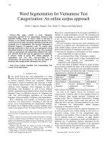
Piezocone soundings provide the most rapid
and detailed approach for soil profiling. The chart
in Fig. 3.1 is one widely used example of soil type
descriptions derived from CPTU data (Section 5
discusses estimates of s
u
and OCR). Note that the
Zones are imprecise compared to the Unified Soil
Classification (USC) system and thus the site
investigation must also include sampling for final
classification of soft cohesive strata. However,
CPTU testing can readily differentiate between
soft cohesive and free draining deposits and the
presence of interbedded granular-cohesive soils.
Dissipation tests should be run in high
permeability soils (especially in deep layers) to
check the ground water conditions (hydrostatic,
artesian or pumping).
Figure 3.1 Soil Behavior Type Classification Chart Based on Normalized CPT/CPTU Data (after
Robertson 1990, Lunne et al. 1997b)
6
The final developed soil profile should always
include the USC designation for each soil type.
Cohesive test specimens should be mixed at their
natural water content for determination of
Atterberg Limits and Liquidity Index. Atterberg
Limits on dried soil are appropriate only to
distinguish between CL-CH and OL-OH
designations (as per ASTM D2487) since drying
can cause very significant reductions in plasticity.
Table 3.1 illustrates this fact for the soft Bangkok
Clay: oven drying predicts a sensitive CL soil,
whereas it actually is an insensitive CH-OH soil.
Values of specific gravity are needed to check the
degree of saturation of test specimens and to
compute unit weights from profiles of average w
n
.
Hydrometer analyses are less important, although
knowledge of the clay fraction (% - 2µm) and
Activity = PI/Clay Fraction may help to explain
unusual properties.
The geotechnical report should contain
appropriate summary plots of the results from at
least the Atterberg Limits (e.g., a Plasticity Chart
and depth vs. w
n
relative to the Liquid and Plastic
Limits), the variation in unit weights, and the
ground water conditions. These data help to
develop a conceptual framework of the anticipated
engineering behavior. Even though of little
interest to many clients, this exercise insures that
someone has evaluated the data and also greatly
assist peer review. The first author has spent
untold hours in developing such plots from
tabulated data for consulting projects worldwide.
Finally, the approach and scope selected to
determine soil stratigraphy obviously should be
compatible with available knowledge regarding
the site geology, prior results from exploration
programs, and the size and difficulty of the
proposed construction.
Table 3.1 Atterberg Limits on Soft Bangkok
Clay
Preparation
w
n
(%)
LL
(%)
PL
(%)
PI
(%)
LI
Oven Dried 65 48 25 23 1.7
Natural 60 69 25 44 0.8
Note:
• Representative values from two
exploration programs.
• Clay minerals = montmorillonite > illite >
kaolinite and clay contains < 5% organic
matter (Ladd et al. 1971)
4 UNDISTURBED SAMPLING & SAMPLE
DISTURBANCE
4.1 Sources of Disturbance and
Procedures to Minimize
Figure 4.1 illustrates potential sources of
sample disturbance via a hypothetical stress path
during the process of obtaining a tube sample for
laboratory testing. Point 1 is the initial stress state
for a low OCR clay and the dashed line from
Point 1 to Point A represents in situ undrained
shear in triaxial compression. The following
describes the different steps of the overall
sampling process and recommends procedures to
minimize the amount of disturbance.
Step 1. Drilling Boring and Stress Relief: Path
1-2. Drilling to the sampling depth reduces the
total vertical stress (σ
v
), and hence subjects the
clay at the bottom of the hole to undrained shear
in triaxial extension (TE). The point at which σ
v
equals the in situ total horizontal stress (σ
h0
)
represents the "perfect sample", i.e., the undrained
release of the in situ shear stress with an effective
stress of σ'
ps
. However, if the weight of the
drilling mud is too low, the soil at the bottom of
the borehole can experience an undrained failure
in TE before being sampled. This important fact is
illustrated in Fig. 4.2. For the conditions given in
the upper right sketch, the bottom three lines show
the weight of mud producing failure as a function
of the boring and water table depths for typical
normally consolidated clays of low, intermediate
and high plasticity. The insert gives the relevant
clay properties used with the following equation
to calculate when σ
h0
– σ
v
= 2s
u
(E)
)
z
z
γ
γ
)(' (E)/σ2s - (K
z
z
1
γ
w
w
b
v0u0
w
w
m
++−=
γ
(4.1)
The weight of mud required to prevent failure
increases significantly with boring depth, i.e., with
decreasing z
w
/z. Failure occurs when z
w
/z is less
than 0.15 if the mud does not have a weight 10 ±
10% greater than water at NC clay sites.
Recommendations
To prevent excessive disturbance before
sampling, be sure that the borehole remains filled
with drilling mud having a weight that falls on
Fig. 4.2 at least half way between a state of failure
(lower three lines) and perfect sampling (upper
three lines). If the clay is overconsolidated, the
values of K
0
and s
u
(E)/σ'
v0
in Eq. 4.1 can be
increased by OCR raised to the power 0.5 and 0.8,
respectively. For conditions that deviate from
those in Fig. 4.2, make independent calculations.
7
Figure 4.1 Hypothetical Stress Path During Tube Sampling and Specimen Preparation of
Centerline Element of Low OCR Clay (after Ladd and Lambe 1963, Baligh et al. 1987)
Step 2. Tube Sampling: Path 2 – 5. Baligh et
al. (1987) used the Strain Path Method (Baligh
1985) to show that, for tubes with an inside
clearance ratio (ICR = (D
i
– D
e
)/D
e
, where D
i
and
D
e
are the inside diameters of the interior tube and
its cutting edge, respectively) greater than zero,
the centerline soil experiences shear in triaxial
compression ahead of the tube (Path 2 – 3),
followed by shear in triaxial extension as it enters
the tube (Path 3 – 4), and then triaxial
compression (Path 4 – 5). The magnitude of the
peak axial strain in compression and extension
increases with tube thickness (t) to diameter ratio
and ICR, and approaches about one percent for
the standard 3 in. diameter Shelby tube (ASTM
1587: D
0
= 76.2 mm, t = 1.65 mm, ICR < 1%).
More recent research (Clayton et al. 1998) studied
the details of the cutting edge and indicates that a
sharp cutting edge with zero inside clearance
should give the best quality samples (peak
extension ε
a
= 0) for soft clays since their low
remolded strength already provides minimal
resistance between the soil and the tube.
Recommendations
Use minimum outside tube diameter D
0
= 76
mm, tube wall thickness such that D
0
/t > 45 with
sharp cutting edge, and ICR near zero (certainly
less than 0.5%). Use new tubes made of brass,
stainless steel or coated (galvanized or epoxy)
steel to help minimize corrosion.
Step 3. Tube Extraction: Path 5 – 6. (Note that
stress path 5 – 6 shown in Fig. 4.1 is highly
speculative). The intact clay just below the bottom
of the tube resists removal of the tube sample,
both due to its strength and the suction created in
the void upon removal. In addition, the pore water
pressure in the clay reduces as the tube is brought
to the ground surface, which may lead to the
formation of gas bubbles due to exsolution of
dissolved gas (e.g., Hight 2003). This is a severe
problem with some deep water clays, wherein gas
voids and cracks form within the tube and the
sample actually expands out of the tube if not
immediately sealed off.
8
Recommendations (Non-gaseous clays)
Tube samples should be obtained with a
stationary (fixed) piston sampler both to control
the amount of soil entering the tube and to better
retain the soil upon extraction. Piston samplers
usually yield far better recovery and sample
quality than push samples. After advancing the
tube, allow time for the clay to partially bond to
the tube (i.e., consolidation and strengthening of
the remolded zone around the sample perimeter),
then slowly rotate the tube two revolutions to
shear the soil, and finally slowly withdraw the
sample. ASTM D6519 describes a hydraulically
operated (Osterberg type) sampler. The Acker
sampler, which uses a rod to advance the piston,
provides better control of the relative position of
the piston head, but is more difficult to operate
(Germaine 2003). Tanaka et al. (1996) and
subsequent experience with the Japanese standard
piston sampler (JPN, D
i
= 75 mm, t = 1.5 mm,
taper angle = 6°, ICR = 0) indicate excellent
sample quality in low OCR clays usually
comparable to that of the large diameter (208 mm)
Laval sampler. The JPN has one version with
extension rods for work on land at relatively
shallow depths (< 20 m) and a hydraulic version
for larger depths and offshore work (Tanaka
2003).
After obtaining the tube, remove spoil from the
top and about 2 cm of soil from the bottom, run
Torvane tests on the bottom, and seal the tubes as
recommended in ASTM D4220.
Step 4. Transportation and Storage: Path 6 –
7. The path in Fig. 4.1 assumes that the tubes are
carefully handled and not subjected to large
changes in temperature (especially freezing).
Hence the decrease in effective stress occurs
solely due to an increase in water content within
the central portion of the tube. The more disturbed
clay around the perimeter consolidates, which
causes swelling of the interior portion. Further
swelling can occur if the sample contains
relatively permeable zones which become
desaturated by the more negative pore pressures
(higher soil suction) in the surrounding clay.
Some organizations extrude the sample in the
field in order to reuse the tubes and to avoid the
development of bonding between the soil and
inner wall of the tube. Others (e.g., NGI, Lunne
2003) may use field extrusion with relatively
strong clay (s
u
> 25 kPa) in order to remove the
outer highly disturbed clay, and then store the
samples in waxed cardboard containers so as to
minimize swelling of the interior clay. Both
practices require, however, very careful extrusion
and handling techniques to avoid distortion (shear
deformation) of the soil that may damage its
structure. The authors prefer to deal with the
problem of constrained swelling (i.e., by
reconsolidation) than to increase the risk of
destructuring the soil, which decreases the size of
its yield (bounding) surface (e.g., Hight 2003).
Recommendations
Leave the soil in the tubes and pack for
shipping (if necessary) following the guidelines
set forth in ASTM D4220. The cost of tubes is far
less than money wasted by running expensive
consolidation and strength tests on disturbed soil.
Figure 4.2 Effect of Drilling Mud Weight and
Depth to Water Table on Borehole Stability for
OCR = 1 Clays
Step 5. Sample Extrusion: Path 7 – 8. (stress
path also highly speculative). The bond that
develops between the soil and the tube can cause
very serious disturbance during extrusion. For
example, portions of the fixed piston tubes of
BBC for the CA/T Special Test Program (Fig. 4.6)
Normalized Depth to Water Table, z
w
/z
0.0 0.1 0.2 0.3
Normalized Weight of Drilling Mud,
γ
m
/
γ
w
0.8
0.9
1.0
1.1
1.2
1.3
1.4
1.5
1.6
For
σ
v
= σ
h0
For σ
v
at
Failure
H
L
L
I
I
Bore hole
H
σ
h0
z
σ
v
= zγ
m
z
w
H High 0.45 0.7 0.22
I Inter. 0.65 0.6 0.18
L Low 0.85 0.5 0.14
Line Plasticity γ
b
/γ
w
K
0
s
u
(E)/σ'
v0
9
were cut in short lengths for a series of
conventional oedometer tests by Haley & Aldrich,
Inc. During extrusion of the deep, low OCR
samples, disturbance caused cracks to appear on
the upper surface, even though the cut tubes were
only several centimeters long. The resultant
compression curves produced OCRs less than one,
whereas subsequent tests on debonded specimens
gave reasonable results.
Recommendations
Cut the tubes with a horizontal band saw or by
hand using a hacksaw (pipe cutters will distort the
tube) with lengths appropriate for each
consolidation or shear test. Perform index tests
(w
n
and strength tests such as Torvane or fall
cone) on soil above and below the cut portion as a
check on soil quality and variability and then
debond the soil with a piano wire before extrusion
as illustrated in Fig. 4.3.
Step 6. Index Tests and Specimen
Preparation: Path 8 – 9. The test specimen may
experience a further decrease in effective stress
(to end up at σ'
s
) due to stress relief (loss of tube
confinement), disturbance during trimming and
mounting, and suction of water from wet porous
stones. Drying would of course increase σ'
s
. In
any case, the pretest effective stress for reasonable
quality samples of non-cemented clays is likely to
be in the range of σ'
s
/σ'
ps
≈ 0.25 to 0.5 for
relatively shallow soil of moderate OCR and in
the range of σ'
s
/σ'
ps
≈ 0.05 to 0.25 for deeper soil
with OCR < 1.5. (Note: σ'
ps
roughly approximates
the in situ mean (octahedral) effective stress).
Figure 4.3 MIT Procedure for Obtaining Test Specimen from Tube Sample (Germaine 2003)
10
Hight et al. (1992) present a detailed study of
the variation in σ'
s
for the plastic Bothkennar Clay
as a function of sampler type (including block
samples), sample transport and method of
specimen preparation.
Finally Fig. 4.1 shows the expected effective
stress path for a UU triaxial compression test
starting from Point 9. The large decrease in σ'
s
compared to the in situ stresses causes the soil to
behave as a highly overconsolidated material.
Recommendations
Prepare test specimens in a humid room (to
minimize drying) with a wire saw, perhaps
supplemented with a lathe or very sharp cutting
ring. Do not use a miniature sampler. Collect soil
above and below the specimen for w
n
. If running
Atterberg Limits, get w
n
on well mixed soil.
Whether to mount the specimen on wet versus dry
stones is controversial. The authors favor moist
stones for tests on low OCR clays that require
back pressure saturation (e.g., CRSC or CU
triaxial).
4.2 Radiography
ASTM D4452 describes the necessary
equipment and techniques for conducting X-ray
radiography. The ability of X ray photons to
penetrate matter depends on the density and
thickness of the material and the resulting
radiograph records the intensity of photons
reaching the film. MIT has been X-raying tube
samples since 1978 using a 160 kV generator. The
back half of the tube is placed in an aluminum
holder (to create a constant thickness of
penetrated material) and a scale with lead
numbers and letters attached at one inch intervals
is used to identify the soil location along the
tubes. The applied amperage and exposure time
vary with distance, tube diameter and average soil
density. Each tube requires two or three films and,
at times, the tube is rotated 90° for a second set.
Radiography can identify the following
features.
1.
Variations in soil type, at least granular vs.
cohesive vs. peat.
2.
Soil macrofabric, especially the nature
(thickness, inclination, distortion, etc.) of any
bedding or layering (uniform varved clays
produce beautiful photos).
3.
The presence of inclusions such as stones,
shells, sandy zones and root holes.
4.
The presence of anomalies such as fissures
and shear planes.
5.
The varying degree and nature of sample
disturbance, including
• bending near the tube perimeter
• cracks due to stress relief, such as may
result from gas exsolution
• gross disturbance caused by the pervasive
development of gas bubbles
• voids due to gross sampling disturbance,
especially near the ends of the tube.
Many of these features are well illustrated in
ASTM D4452
Radiography is extremely cost effective since it
enables one to logically plan a laboratory test
program (i.e., where to cut the tubes for each
consolidation and shear test) based on prior
knowledge of the locations of the best quality
material of each representative soil obtained from
the site. Radiography greatly reduces the
likelihood of running costly tests on poor quality
or non-representative soil that produce misleading
data.
Recommendations
Radiography is considered essential for projects
having a limited number of very expensive
samples (e.g., for offshore projects) or that require
specialized stress path triaxial tests. For example,
NGI has used on-board radiography to
immediately assess sample quality for offshore
exploration and Boston's CA/T project used
radiography for many undisturbed tube samples.
The authors believe that each geotechnical
"community" should have access to a regional
radiography facility that can provide economical
and timely service.
4.3 Assessing Sample Quality
No definitive method exists to determine the
absolute sample quality vis-à-vis the "perfect
sample". It is especially difficult to distinguish
between decreases in σ'
s
due solely to constrained
swelling versus that caused by shear distortions.
The former should have minimal effect on
consolidation properties (Section 6) or undrained
shear if the soil is reconsolidated to the in situ
stresses (Section 8). In contrast, the later produces
irreversible destructuration (disturbance of the soil
fabric, breaking of cementation and other
interparticle bonds, etc.) that alters basic behavior
depending upon the degree of damage to the soil
structure (e.g., Lunne et al. 1997a, Santagata and
Germaine 2002, Hight and Leroueil 2003). Never-
the-less, one still should attempt to assess sample
quality using the approaches described below.
1. Radiography. The distinct advantages of this
non-destructive method should be obvious
(Section 4.2).
11
2. Strength Index Tests. Disturbance decreases
the unconsolidated-undrained (UU) strength so
that Torvane, lab vane, fall cone and similar tests
will reflect relative changes in s
u
within and
between tube samples. Figure 4.3 shows how
index tests can be used for each specimen selected
for consolidation and CU shear tests.
Figures 4.4 and 4.5 illustrate how MIT used
index tests to help assess the effects of disturbance
on consolidation testing to measure the stress
history of a offshore Venezuelan CH clay. Azzouz
et al. (1982) describe the nature of the deposit and
the sampling and testing procedures at the site
having a water depth of 78 ft. Radiography of the
top foot of a deep sample showed gross
disturbance above marker U (the UUC test was
purposely run on disturbed soil), whereas Oed.
No. 12 was run on presumed (from the X-ray)
good quality soil with a much higher Torvane
strength (Fig. 4.4). Although the compression
curve (Fig. 4.5) looked reasonable, the estimated
σ'
p
indicated that the deposit was
"underconsolidated". A second test (No. 18) was
run as a check and, although only two inches
deeper, it gave OCR = 1.2, plus a S-shaped curve
with a significantly higher maximum CR. The
Torvane strength also was much higher and equal
to that measured onboard. Based on this
experience, the location of the first engineering
test was subsequently guided by both the X-ray
and Torvane data. It is also useful to compare
strengths normalized by σ'
vo
(e.g., see example in
Fig. 7.9).
3. Pretest Effective Stress (
σ
'
s
). Measurement of
σ'
s
requires a fine porous stone (air entry pressure
greater than the soil suction = σ'
s
) connected to a
fully saturated, rigid system. For relatively
unstructured clays (e.g., little or no cementation),
decreases in σ'
s
generally will correlate with
decreases in s
u
from UU type tests. For example,
samples of NC resedimented Boston Blue Clay
(BBC) subjected to varying degrees of disturbance
(see Fig. 7.7) showed a unique correlation
between log[s
u
(UUC)/σ'
s
] and log[σ'
v0
/σ'
s
] as per
the SHANSEP equation (Santagata and Germaine
2002). However, UU tests are not recommended
for design (Section 7.2) and thus the real question
is whether σ'
s
reflects the degree of damage to the
soil structure that will alter consolidation and
reconsolidated strength test results. The answer is
maybe yes and maybe no depending on the soil
type and the relative contributions of constrained
swelling versus shear distortions on the value of
σ'
s
.
Figure 4.4 Results of Radiography and s
u
Index Tests on Deep Tube Sample of Offshore Orinoco
Clay (from Ladd et al. 1980)
s
u
(kPa)
0 102030405060
Torvane
UUC
TESTS
Atterberg Limits
(n = 3)
LL = 101 2
PI = 60 3
Depth Below Mudline, z (ft)
127.0
127.5
128.0
N P Q R S T U V W X Y Z - E
Markings
X-Ray
Wax
Void
UUC No. 4
w
n
= 72.2%
OED No. 12
w
n
= 64.8%
OED No. 18
w
n
= 66.5%
Torvane
Onboard
+
+
12
Figure 4.5 Results of Oedometer Tests on Deep
Tube Sample of Offshore Orinoco Clay (from
Ladd et al. 1980)
4. Vertical Strain at Overburden Stress (
ε
v0
).
This quantity equals the vertical strain measured
at σ'
v0
in 1-D consolidation tests. Andresen and
Kolstad (1979) proposed that increasing sample
disturbance should result in increasing values of
ε
v0
. Terzaghi et al. (1996) adopted this approach,
coined the term Specimen Quality Designation
(SQD) with sample quality ranging from A (best)
to E (worst), and suggested that reliable lab data
required samples with SQD of B or better for
clays with OCR < 3 – 5. Figure 4.6 shows the
SQD criteria superimposed on elevation vs. ε
v0
and stress history data for the CA/T South Boston
BBC test site described in Section 5.2. While most
of the tests within the thick crust met the SQD A –
B criteria, almost none did in the deep, low OCR
clay even though the non-deleted tests produced
excellent S-shaped compression curves, i.e.,
decreasing CR with increase in σ'
v
. (Note: values
of ε
v0
for many of the deleted oedometer tests,
which were disturbed during extrusion, were not
available to plot). Tanaka et al. (2002) also
concluded that ε
v0
cannot be universally correlated
to sample quality based on reconsolidation data on
tube samples from eight worldwide Holocene
clays and the 350 m thick Osaka Bay Pleistocene
clay. The latter showed OCR ≈ 1.5 ± 0.3
independent of ε
v0
ranging from 1.8 to 4.2%,
although ε
v0
did prove useful for at least one of
the former sites. Note that NGI recently proposed
using ∆e/e
0
rather than ε
v0
(Lunne et al. 1997a).
5. Variation in Maximum Virgin Compression
Ratio (CR
max
). Clays with an S-shaped virgin
compression line indicate that the material is
structured and damage to this structure will reduce
the value of CR
max
, and also σ'
p
. For example,
high quality samples of the deep low OCR BBC at
the CA/T test sites generally gave values of CR
max
ranging from 0.4 to 0.7, whereas CR
max
≈ 0.25 ±
0.05 from consolidation tests having OCRs less
than one (the deleted tests in Fig. 4.6) (Ladd et al.
1999).
Figure 4.7 shows another example from
oedometer tests run on tube samples (extruded in
the field) of a highly plastic organic clay for a
major preload project on a 15 m thick Nigerian
swamp deposit. The engineer simply selected a
mean CR from all the tests, whereas the data from
less disturbed samples with an OCR ≥ 1 clearly
show that CR
max
increases significantly with
natural water content. This relationship was then
used with the variation in w
n
with depth to select
more realistic values of CR for design.
Recommendations
1. Strength index tests (Torvane, lab vane, etc.)
should be run above and below all specimens
being considered for engineering tests in
order to assess relative changes in sample
quality. Also evaluate s
u
normalized by σ'
v0
.
2.
All consolidation and CK
0
U tests should
report the vertical strain (ε
v0
) at the effective
overburden stress to help assess relative
changes in sample quality at comparable
depths and perhaps as a rough measure of
absolute quality.
3.
Compare values of CR
max
since structural
damage will reduce this parameter (and also
σ'
p
), especially for soils with S-shaped virgin
compression curves.
4.
Radiography is strongly recommended as it
provides an excellent method for identifying
the best quality soil for consolidation and CU
strength tests.
5.
Measurements of σ'
s
on representative
samples can be useful if a suitable device is
readily available.
Note that items 1, 2 and 3 (and perhaps 5) involve
little or no extra cost and that radiography is
highly cost effective.
Consolidation Stress, σ'
v
(kPa)
10 100 1000
EOP Vertical Strain,
ε
v
(%)
0
5
10
15
20
25
30
Oed. No. 12
σ'
p
= 132 kPa
OCR = 0.58
CR = 0.25
Oed. No. 18
σ'
p
= 270 kPa
OCR = 1.2
CR = 0.36
σ' = zγ
b
= 227 kPa
13
Figure 4.6 (a) Specimen Quality Designation and (b) Stress History for Boston Blue Clay at CA/T
South Boston (after Ladd et al. 1999 and Haley and Aldrich 1993)
Figure 4.7 Effects of Sample Disturbance on CR
max
from Oedometer Tests (LIR = 1) on Highly
Plastic Organic Clay (numbers are negative elevation (m) for OCR ≥ 1; GS El. = + 2m)
Natural Water Content, w
n
(%)
60 70 80 90 100 110 120 130 140
Max. Virgin Compression Ratio, CR
max
0.1
0.2
0.3
0.4
0.5
0.6
OCR 1
OCR < 1 (Disturbed)
7.9
7.9
9.3
4.2
11.5
2.0
11.2
11.9
12.4
6.0
2.6
3.1
>
Stress (kPa)
0 200 400 600 800
ε
v
at σ'
vo
(%)
04812
Elevation (ft), MSL
-120
-100
-80
-60
-40
AB EC
SQD
D
σ'
vo
σ'
p
selected
(a)
(b)
Tube Sample
Test Deleted
Block Sample
ε
v
data not available for some "Test Deleted" tests
ε
v
plot includes data from Recompresson TX tests
.
.
14
5 IN SITU TESTING
This section discusses the use of the field vane
test (FVT) and the piezocone (CPTU) for the
purpose of measuring spatial variations in
undrained shear strength and stress history. It also
evaluates the ability of these tests to obtain design
values of s
u
and OCR as opposed to only relative
changes in these parameters.
5.1 Field Vane Test
Testing Technique The preferred approach for
measuring s
u
(FV) in medium to soft clays (s
u
≤ 50
kPa) has the following features.
• Equipment: four blades of 2 mm thickness
with sharpened square ends, diameter (d) =
50 to 75 mm and height (h) = 2d; a gear
system to rotate the vane and measure the
torque (T); and the ability to account for rod
friction. The SGI-Geonor device (designation
H-10, wherein the vane head is encased in a
sheath at the bottom of the casing and then
extended to run a test) and the highly portable
Nilcon device (wherein a rod pushes the vane
into the ground) are recommended. The
Acker (or similar) device with thick tapered
blades which are rotated via a handheld
torque wrench is not recommended due to
increased disturbance during insertion
followed by shearing at a rate that is much
too fast (failure in seconds rather than
minutes).
• Procedure: push vane tip to at least 5 times d
(or borehole diameter); after about one
minute, rotate at 6
°/min to obtain the peak
strength within several minutes; then rotate
vane 10 times prior to measuring the
remolded strength. Compute the peak and
remolded strengths using
2d)h(for
d7
6T
6
d
2
hd
T
(FV)s
3
32
u
=
π
=
+π
= (5.1)
which assumes full mobilization of the same shear
stress on both the top and sides of a cylindrical
failure surface.
Interpretation of Undrained Shear Strength. It
is well established that the measured s
u
(FV)
differs from the s
u
(ave) appropriate for undrained
stability analyses due to installation disturbances,
the peculiar and complex mode of failure and the
fast rate of shearing (e.g., Art. 20.5 of Terzaghi et
al. 1996). Hence the measured values should be
adjusted using Bjerrum's (1972) empirical
correction factor (µ) vs. Plasticity Index derived
from circular arc stability analyses of
embankment failures [µ = 1/FS computed using
s
u
(FV)]. Figure 5.1 shows this correlation, the data
used by Bjerrum and more recent case histories.
The coefficient of variation (COV) ranges from
about 20% at low PI to about 10% at high PI for
homogeneous clays (however, Fig. 20.21 of
Terzaghi et al. 1996 indicates COV ≈ 20%
independent of PI). Note that the presence of
shells and sandy zones can cause a large increase
in s
u
(FV), as shown by the "FRT" data point (very
low µ) for a mud flat deposit.
Bjerrum's correction factor ignores three-
dimensional end effects, which typically increase
the computed FS by 10 ± 5% compared to plane
strain (infinitely long) failures (Azzouz et al.
1983). Hence the µ factor should be reduced by
some 10% for field situations approaching a plane
strain mode of failure or when the designer wants
to explicitly consider the influence of end effects
(see Section 7).
Interpretation of Stress History. Table VI and
Fig. 8 of Jamiolkowski et al. (1985) indicate that
the variation in s
u
(FV)/σ'
v0
with overconsolidation
ratio can be approximated by the SHANSEP
equation
fv
m
(OCR)S
'
(FV)s
FV
v0
u
=
σ
(5.2a)
where S
FV
is the NC undrained strength ratio for
clay at OCR = 1. Chandler (1988) adopted
Bjerrum’s (1972) correlation between s
u
(FV)/σ'
v0
for OCR = 1 "young" clays vs. Plasticity Index
and m
fv
= 0.95 in order to predict OCR from field
vane data, i.e.,
1.05
FV
v0u
S
'(FV)/s
OCR
σ
=
(5.2b)
Figure 5.2 compares measured values of S
FV
and
m
fv
for ten sites having homogeneous clays (no
shells or sand) and PI ≈ 10 to 60% with
Chandler's proposed correlation. The agreement in
S
FV
is quite good (error = 0.024 ± 0.017), and
excluding the three cemented Canadian clays (for
which m
fv
> 1), m
fv
= 0.89 ± 0.08 compared to
1/1.05 = 0.95 selected by Chandler (1988). Less
well documented experience suggests that Eq.
5.2b and Fig. 5.2 also yield reasonable predictions
15
of OCR for highly plastic CH clays with PI >
60%. It is interesting to note that the decrease in µ
and increase in S
FV
with PI vary such that µS
FV
=
0.21 ± 0.015 for PI > 20%, which is close to the
0.22 recommended by Mesri (1975) for clays with
m near unity.
Figure 5.1 Field Vane Correction Factor vs. Plasticity Index Derived from Embankment Failures
(after Ladd et al. 1977)
Figure 5.2 Field Vane Undrained Strength Ratio at OCR = 1 vs. Plasticity Index for Homogeneous
Clays (no shells or sand) [data points from Lacasse et al. 1978 and Jamiolkowski et al. 1985]
Plasticity Index, PI (%)
0 102030405060708090100
S
FV
= s
u
(FV)/
σ
'
v0
at OCR = 1
0.10
0.15
0.20
0.25
0.30
0.35
Canadian Cemented
Other CL & CH Clays
Chandler (1988)
m = 0.95
0.77
0.90
0.80
0.97
0.93
1.51
0.96
0.87
1.35
1.18
m
m
Plasticity Index, PI (%)
0 20 40 60 80 100 120
Correction Factor,
µ
0.4
0.6
0.8
1.0
1.2
1.4
||
||
||
||
||
||
Bjerrum's (1972)
Recommended Curve
Flaate & Preber (1974)
Ladd & Foott (1974)
Milligan (1972)
LaRochelle et al. (1974)
Bjerrum (1972)
*
*
* Layered and Varved Clays
FRT (contains shells and sand)
16
Case History. Figure 5.3 shows the location of
approach abutments with preload fills for two
bridges that are part of a highway reconstruction
project founded on 40 m of a varved to irregularly
layered CH deposit in Northern Ontario.
Construction of the preload fills started on the
East side in early October, 2000. Massive failures
occurred almost simultaneously at both abutments
when the steeply sloped reinforced fill reached a
thickness of about 4 m. The sliding mass extended
to the opposite (West) bank of the river. The
figure also shows the location of three
preconstruction CPTU soundings and two borings
(B95-9 and B97-12) with 75 mm push tube
samples and FV tests. Boring B01-8 on the West
side was made after the failure, but before any
filling, and did not include FV tests. Subsequent
discussion focuses on the upper 15 to 20 m of clay
since it is most relevant to the stability and
settlement of the preload fills.
Figure 5.3 Location Plan of Bridge Abutments
with Preload Fill and Preconstruction Borings
and In Situ Tests
Figure 5.4 presents summary plots of water
contents, measured FV strengths and stress history
prepared by the first author, who was hired to
investigate the failure by the design-build
contractor. The clay has an average PI of about
50% and a Liquidity Index near unity. The two
s
u
(FV) profiles on either side of the river are very
similar, with an essentially linear increase with
depth. The scatter is relatively small considering
the fact that the tests were run with thick, Acker
type blades and a torque wrench. However, the
recorded sensitivity of only S
t
= 3 – 6 is too low
based on the high Liquidity Index of the clay. It is
interesting to note that the two CPTU soundings
on the West side predicted strengths some 25%
and 80% higher than the one sounding on the East
side, i.e., much larger differences than shown by
the field vane data. The preconstruction site
investigation included only two consolidation
tests within the upper 15 m. The range in σ'
p
shown in Fig. 5.4 reflects uncertainly in the
location of the break in the S-shaped compression
curves because the tests doubled the load for each
increment (LIR = 1).
Chandler's (1988) method was used with S
FV
=
0.28 in Eq. 5.2b (for PI = 50%) to predict the
variation in σ'
p
(FV) with depth. The results are
plotted in Fig. 5.5 and show good agreement with
the two lab tests. Because the agreement may
have been fortuitous, and due to uncertainty in
virgin compressibility and an appropriate design
s
u
/σ'
vc
for the layered deposit, tube samples from
boring B97-12 were sent to MIT for testing. The
tubes were X-rayed and clay extruded using the
cutting-debonding technique illustrated in Fig. 4.3
for several CRS consolidation and SHANSEP
CK
0
U direct simple shear (DSS) tests. In spite of
using 4-year old samples, the test results were of
exceptional quality, e.g., see the CRS
consolidation data in Fig. 6.5. Four values of σ'
p
from the MIT tests are plotted in Fig. 5.5, leading
to the conclusion that the σ'
p
(FV) profiles were
reasonable for virgin clay (Note: three DSS tests
on NC clay gave s
u
/σ'
vc
= 0.205 ± 0.004 SD).
5.2 Piezocone Test
Testing Technique. Figure 5.6 illustrates the
bottom portion of a 10 to 20 metric ton capacity
60° piezocone having a base area of 10 cm
2
(15
cm
2
is less common), a base extension of h
e
≈ 5
mm, a filter element of h
f
≈ 5 mm to measure
penetration pore pressures (denoted as u
2
for the
filter located at the cylindrical extension of the
cone), a dirt seal at the bottom of the friction
sleeve and an O-ring to provide a water tight seal.
A temperature compensated strain gage load cell
measures the force (Q
c
) required to penetrate the
cone (cone resistance q
c
= Q
c
/A
i
, A
i
= internal
area of recessed top of cone) and a pressure
transducer measures u
2
. The porous filter element
(typical pore size ≤ 200 µm) is usually plastic and
filled with glycerin or a high viscosity silicon oil
(ASTM D5778). Since the u
2
pressure acts around
the recessed top rim of the cone, the corrected
actual tip resistance is
q
t
= q
c
+ u
2
(1-a) (5.3)
where a = net area ratio = A
i
/A
cone
(should
approach 0.8, but may be only 0.5 or lower, and
must be measured in a pressure vessel).
17
Figure 5.4 Depth vs. Atterberg Limits, Measured s
u
(FV) and Stress History for Highway Project in
Northern Ontario
Figure 5.5 Revised Stress History with σ'
p
(FV)
and MIT Lab Tests
Figure 5.6 Illustration of Piezocone (CPTU)
with Area = 10 cm
2
(adapted from ASTM
D5778 and Lunne et al. 1997b)
σ'
v0
and σ'
p
(kPa)
0 50 100 150 200
Depth, z (m)
0
5
10
15
20
||
||
West: σ'
p
(FV)
East
σ'
v0
CRSC
CK
0
UDSS
MIT σ'
p
B97-12
σ'
p
(FV), S
FV
= 0.28
East
West
w (%)
20 40 60 80 100
Depth, z (m)
0
5
10
15
20
||
||
||
||
||
||
s
u
(FV) (kPa)
20 40 60
σ'
v0
and σ'
p
(kPa)
50 100 150 200
||
||
West
East
σ'
v0
σ'
p
from 24 hr
IL oedometer
PL
LL
Boring
Sym.
97-12
95-9
01-8
18
The cone is hydraulically penetrated at 2 cm/s
with records of q
c
, sleeve friction (f
s
) and u
2
at
minimum depth intervals of 5 cm. Penetration
stops each minute or so to add 1-m lengths of high
tensile strength push rods (this affects the data,
which should be noted or eliminated). It also is
stopped to run dissipation tests, i.e., decrease in u
2
with time, by releasing the force on the push rods.
Quantitative interpretation of piezocone data in
soft clays requires very accurate measurements of
q
c
, u
2
and q
t
(f
s
approaches zero in sensitive soils).
ASTM D5778 recommends load cell and pressure
transducer calibrations to 50% of capacity at the
start and finish of each project and zero readings
before and after each sounding. System overload,
rod bending, large temperature changes
(inclinometers and temperature sensors are wise
additions) and failure of the O-ring seal, as
examples, can cause erroneous readings.
Desaturation of the pore pressure system is a
pervasive problem since relatively coarse filters
can easily cavitate during handling or during
penetration in soil above the water table and in
dilating sands below the water table. Hence
ASTM recommends changing the filter element
after each sounding (from a supply of carefully
deaired filters stored in saturated oil). However, it
still may be difficult to detect u
2
readings in soft
clays that are too low, which in turn reduces the
value of q
t
. Figure 5.7 illustrates an extreme, but
typical, example from pre-bid CPTU soundings
for the I-15 reconstruction design-build project in
Salt Lake City. Poor saturation and possible
cavitation in sand layers caused values of u
2
to be
even less than the initial in situ pore pressure (u
0
)
in underlying low OCR clays. The resulting
erroneous q
t
data negated development of site
specific correlations for using the very extensive
piezocone soundings for s
u
and stress history
profiling during final design.
Figure 5.7 Example of Very Low Penetration Pore Pressure from CPTU Sounding for I-15
Reconstruction, Salt Lake City (record provide by Steven Saye)
q
c
(MPa)
02468
Depth, z (m)
0
5
10
15
20
u
2
(kPa)
0 200 400 600 800
Equilibrium u
0
Recent
Alluvium
Interbedded
Alluvium
Deposits
Bonneville
Clay
Interbedded
Deposits
Culter
Clay
Measured pore
pressure
"Correct" pore
pressure suggested
by contractor
19
Interpretation of Undrained Shear Strength.
The undrained shear strength from the piezocone
test, s
u
(CPTU), relies on empirical correlations
between q
net
= (q
t
– σ
v0
) and reference strengths
determined by other testing methods. This
approach gives values of the cone factor, N
kt
,
equal to q
net
divided by the reference s
u
; hence
s
u
(CPTU) = (q
t
– σ
v0
)/N
kt
= q
net
/N
kt
(5.4)
For undrained stability analyses, the reference
strength should equal s
u
(ave), such as estimated
from corrected field vane data (for homogeneous
clays) or from laboratory CK
0
U testing (as
discussed in Sections 7 and 8). Reported values of
N
kt
typically range from 10 to 20 (e.g., Aas et al.
1986), which presumably reflect differences in the
nature of the clay (e.g., lean and sensitive vs.
highly plastic) and its OCR, the reliability of the
reference strengths, and the accuracy of q
net
.
The large variation in cone factor precludes
direct use of CPTU soundings for calculating
design strengths. One needs a site specific
correlation for each deposit. But be aware that N
kt
may vary between different piezocone devices and
operators (e.g., see Gauer and Lunne 2003).
Moreover, even with the same system, one can
encounter serious discrepancies, as illustrated at
two Boston Blue Clay sites.
One site is at the CA/T Project Special Test
Program location in South Boston (Ladd et al.
1999) and the other at Building 68 on the MIT
campus (Berman et al. 1993). The marine clay at
both sites is covered by 30 ft of fill and either
organic silt or marine sand and has a thick
desiccated crust overlying low OCR clay. Figure
5.8 shows the well defined stress history profiles
developed from several types of 1-D consolidation
tests, mostly run at MIT. The SB deposit has a
thicker crust and extends deeper than the B68
deposit. SB also tends to be more plastic: typical
LL = 50
± 7% and PI = 28 ± 4% versus LL = 40 ±
10% and PI = 18
± 8% at B68. The same
company performed two CPTU soundings at
South Boston and four at MIT using the same
device (A = 10 cm
2
, a = 0.81, 9 mm thick oil
saturated Teflon filter resting 3 mm above the
cone base) in holes predrilled to the top of the
clay. The reference strength profiles were
calculated using the mean stress history and
values of S and m from extensive CK
0
U direct
simple shear (DSS) testing by MIT at both sites.
Figure 5.8 plots the back calculated value of N
kt
,
which differ by almost two fold. The B68 cone
factor is essentially constant with depth, although
the mean PI decreases with depth. Hence the
variation in N
kt
is not thought to be caused by
differences in the plasticity of BBC. The reason
for the discrepancy is both unknown and
worrisome.
Figure 5.8 Comparison of Stress History and CPTU Cone Factor for Boston Blue Clay at CA/T
South Boston and MIT Bldg 68: Reference s
u
(DSS) from SHANSEP CK
0
UDSS Tests (after Ladd et
al. 1999 and Berman et al. 1993)
Stress History, σ'
v0
and σ'
p
(ksf)
0 5 10 15
Elevation (ft), MSL
-120
-100
-80
-60
-40
-20
Cone Factor, N
kt
, for s
u
(DSS)
510152025
Mean of
2 soundings
SB 0.186 0.765
B68 0.202 0.723
SHANSEP CK
0
UDSS
Site S m
σ'
p
σ'
v0
σ'
p
SB
B68
SB
B68
SB
B68
+11
+10
Site GS El. Oed CRS CK
0
-TX DSS
20
Interpretation of Stress History. Numerous
OCR correlations have been proposed based on
q
net
/σ'
v0
, ∆u/σ'
v0
, B
q
= ∆u/q
net
and various
combinations of these parameters. Because the
penetration excess pore pressure (∆u = u – u
0
)
varies significantly with location of the filter
element, especially near the base of the cone
where u
2
is located, the authors prefer correlations
using q
net
. Lunne et al. (1997b) recommend
OCR = k(q
net
/σ'
v0
) (5.5)
with k = 0.3 and ranging from 0.2 to 0.5.
If the deposit has large variations in OCR, a
SHANSEP type equation is preferred for site
specific correlations.
CPTU
v0net
CPTU
1/m
S
'/q
OCR
σ
=
(5.6)
Figure 5.9 plots the CPTU Normalized Net Tip
Resistance versus OCR for the same two BBC
sites just discussed. As expected, the two sites
have very different values of S
CPTU
, since this
parameter equals N
kt
times s
u
(CPTU)/σ'
v0
for
normally consolidated clay. Note, however, that
m
CPTU
= 0.77 ± 0.01 from the two data sets,
whereas Eq. 5.5 assumes that m is unity.
Case History. This project involves
construction of a 800-m long breakwater for the
Terminal Portuario de Sergipe (TPS) harbor
facility located 2.5 km off the coastline of
northeast Brazil. The site has a water depth of 10
m and a soil profile consisting of 4 m of silty sand
and 7 to 8 m of soft plastic Sergipe clay overlying
dense sand. Construction of the initial design with
a small stability berm, as shown by the cross-
section in Fig. 5.10, started in October, 1988. A
failure occurred one year later when the first 100
m length of the central core had nearly reached its
design elevation. Geoprojetos Ltda. of Rio de
Janeiro developed a "Redesign" with the crest axis
moved 39 m seaward and a much wider 5-m thick
stability berm. Figure 5.11 shows the locations of
the access bridge, the initial failure, the plan of the
Redesign, and the locations of relevant borings
and CPTU soundings.
Figure 5.9 Comparison of CPTU Normalized
Net Cone Resistance vs. OCR for BBC at South
Boston and MIT Bldg 68
Figure 5.10 Cross-Section of TPS Breakwater Showing Initial Failure, Redesign, and
Instrumentation at QM2
Overconsolidation Ratio, OCR
110
Q
t
= (q
t
-
σ
v0
)/
σ
'
v0
1
10
2468
2
4
6
8
20
South Boston
CA/T
MIT Bld. 68
Range 4 profiles
Regression Data
Site S
CPTU
m
CPTU
r
2
S. Boston 2.13 0.76 0.97
MIT Bld. 68 3.53 0.78 0.91