Tài liệu Handbook of Electrical Design Details P1 doc
Bạn đang xem bản rút gọn của tài liệu. Xem và tải ngay bản đầy đủ của tài liệu tại đây (488.52 KB, 30 trang )
Copyright © 2003, 1997 by The McGraw-Hill Companies, Inc. All rights reserved. Manufactured in the United States of America.
Except as permitted under the United States Copyright Act of 1976, no part of this publication may be reproduced or distributed in any
form or by any means, or stored in a database or retrieval system, without the prior written permission of the publisher.
0-07-142579-9
The material in this eBook also appears in the print version of this title: 0-07-137751-4.
All trademarks are trademarks of their respective owners. Rather than put a trademark symbol after every occurrence of a trade-
marked name, we use names in an editorial fashion only, and to the benefit of the trademark owner, with no intention of infringe-
ment of the trademark. Where such designations appear in this book, they have been printed with initial caps.
McGraw-Hill eBooks are available at special quantity discounts to use as premiums and sales promotions, or for use in corporate
training programs. For more information, please contact George Hoare, Special Sales, at or (212)
904-4069.
TERMS OF USE
This is a copyrighted work and The McGraw-Hill Companies, Inc. (“McGraw-Hill”) and its licensors reserve all rights in and to the
work. Use of this work is subject to these terms. Except as permitted under the Copyright Act of 1976 and the right to store and
retrieve one copy of the work, you may not decompile, disassemble, reverse engineer, reproduce, modify, create derivative works
based upon, transmit, distribute, disseminate, sell, publish or sublicense the work or any part of it without McGraw-Hill’s prior con-
sent. You may use the work for your own noncommercial and personal use; any other use of the work is strictly prohibited. Your
right to use the work may be terminated if you fail to comply with these terms.
THE WORK IS PROVIDED “AS IS”. McGRAW-HILL AND ITS LICENSORS MAKE NO GUARANTEES OR WARRANTIES
AS TO THE ACCURACY, ADEQUACY OR COMPLETENESS OF OR RESULTS TO BE OBTAINED FROM USING THE
WORK, INCLUDING ANY INFORMATION THAT CAN BE ACCESSED THROUGH THE WORK VIA HYPERLINK OR
OTHERWISE, AND EXPRESSLY DISCLAIM ANY WARRANTY, EXPRESS OR IMPLIED, INCLUDING BUT NOT LIMITED
TO IMPLIED WARRANTIES OF MERCHANTABILITY OR FITNESS FOR A PARTICULAR PURPOSE. McGraw-Hill and its
licensors do not warrant or guarantee that the functions contained in the work will meet your requirements or that its operation will
be uninterrupted or error free. Neither McGraw-Hill nor its licensors shall be liable to you or anyone else for any inaccuracy, error
or omission, regardless of cause, in the work or for any damages resulting therefrom. McGraw-Hill has no responsibility for the con-
tent of any information accessed through the work. Under no circumstances shall McGraw-Hill and/or its licensors be liable for any
indirect, incidental, special, punitive, consequential or similar damages that result from the use of or inability to use the work, even
if any of them has been advised of the possibility of such damages. This limitation of liability shall apply to any claim or cause what-
soever whether such claim or cause arises in contract, tort or otherwise.
DOI: 10.1036/0071425799
ebook_copyright 7x9.qxd 7/23/03 10:51 AM Page 1
CONTENTS
Preface vii
Chapter 1 Planning for Electrical Design 1
Chapter 2 Power Generation and Transmission 37
Chapter 3 Power System Equipment 57
Chapter 4 Substations and Electrical Distribution 109
Chapter 5 Service Entrance, Loadcenters, and Grounding 133
Chapter 6 Wire, Cable, and Circuit Components 173
Chapter 7 Branch Circuit Design and Device Wiring 243
Chapter 8 Lighting, Lamps, and Luminaires 269
Chapter 9 Telephone, Multimedia, and Alarm Systems 321
Chapter 10 Electric Motors and Starters 345
Chapter 11 Emergency and Standby Systems 379
Chapter 12 Electrical Surges and Surge Protection 399
FM_Sclater_137751-4 3/28/03 12:01 PM Page v
PREFACE
This is the second edition of the Handbook of Electrical Design Details (HEDD), orig-
inally published in 1997. It is a well-illustrated reference book on electrical power and
lighting—how it is generated, transmitted, distributed, and used. Considerable new
information has been added in this edition but it is a smaller volume, making it more
user-friendly and easier to keep on a desk or shelf. Among the topics new to this edi-
tion are computer-aided electrical drawing (CAD), basic switch and receptacle circuit
wiring, outdoor low-voltage wiring, telephone and structured wiring, and electrical
surge protection.
This book begins with a discussion of electrical drawing and symbols and the impor-
tance of specifications in electrical projects. The chapters that follow cover power gen-
eration, transmission, and distribution. Design details of generators and transformers and
their role in delivering electric power to consumers’ homes or buildings are included.
Aerial and buried service entrances are explained and illustrated, as are main panels or
loadcenters and the principles of earth grounding.
Properties of wire and cable are presented, and the dimensions and the details of basic
electrical wiring devices are described and illustrated. The rules for installing branch
circuit wiring are given along with an example of a load calculation and the reasons for
load balancing. Extensive coverage is given to lighting, lamps, and indoor and outdoor
lighting design. Other chapters explain telephone and structured wiring, electric motors,
emergency and standby electrical systems, and the essentials of surge protection.
This edition of HEDD makes many references to the
National Electrical Code
®
(NEC
®
)
*
on all topics governed by the code, such as wiring protection, wiring methods
and materials, and standard equipment, where appropriate for reader guidance. In
the chapters on wire, cable, and wiring devices, individual drawings represent whole
classes of standard products such as switches, receptacles, and lamps, replacing the
many repetitive catalog pages that appeared in the first edition.
Each chapter begins with a content summary called “Contents at a Glance” and an
Overview of the chapter. In addition, there are separate glossaries of technical terms
at the ends of the chapters on transformers, electrical service entrance, wiring, light-
ing, motors, telecommunications, emergency and standby systems, and surge protec-
tion, for handy reference and quick memory refreshing.
This second edition of HEDD has been written in an informal descriptive style,
with minimal use of mathematics. The readers most likely to benefit from this book
are electrical contractors, electricians, and instructors. Others who will find this vol-
ume helpful are those employed in the electrical industry in manufacturing, service,
*National Electrical Code and NEC are registered trademarks of the National Fire Protection Association,
Quincy, Massachusetts.
FM_Sclater_137751-4 3/28/03 12:01 PM Page vii
Copyright 2003, 1997 by The McGraw-Hill Companies, Inc. Click Here for Terms of Use.
PLANNING FOR ELECTRICAL
DESIGN
CONTENTS AT A GLANCE
Overview
Electrical Drawing Objectives
Electrical Drawing Preparation
Computer-Aided Drawing
Electrical CAD Software
CAD Drawing Plotters
Drawing Sizes and Conventions
Drawing Reproduction
Drawing Line Widths and Styles
Electrical Graphic Symbols
Electronic Graphic Symbols
Drawing Schedules
Electrical Project Drawings
Electrical Product and Work Standards
What Are Electrical Specifications?
Overview
A successful electrical power and lighting project depends on effective planning in the
form of drawings, schedules, and contract specifications. This contract documentation
provides a concise picture of the objectives for the electrical project work to be done.
It also serves as a record of intent for owners and as instructions and guidance for
1
Ch01_Sclater_1377514 3/27/03 2:31 PM Page 1
Copyright 2003, 1997 by The McGraw-Hill Companies, Inc. Click Here for Terms of Use.
contractors, electricians, installers, and others performing the work. Contract docu-
ments, which might also include surveys and test data, are legal documents, and they
can be used as evidence in court cases involving contractor malfeasance, or failure to
comply with the intent of the drawings and specifications.
The present conformity to accepted formats for drawings and specifications is the
result of years of practical experience reinforced by accepted national and international
standards issued by government agencies and private standards organizations. The stan-
dards organizations are advised by experienced personnel from the ranks of manufac-
turers, contractors, and other interested parties. The intent of standards is to produce
unambiguous documentation that is understandable by all project participants, from
engineers and architects to contractors, project supervisors, electricians, and installers.
This chapter discusses the preparation of drawings and schedules and their repro-
duction. It also explains and illustrates typical standard electrical symbols used on plan-
view, one-line, and schematic drawings for electrical construction, and identifies the
principal government and industry agencies whose standards affect all phases of elec-
trical work. Appendix A is a compilation of American National Standards Institute
(ANSI) electrical symbols and National Electrical Manufacturers Association (NEMA)
plug and receptacle and circuit wiring configuration diagrams. Appendix B contains the
front matter and selected commonly used sections of a typical electrical specification,
to show how a written specification is organized, its legal language, and its style.
Electrical Drawing Objectives
Drawing for an electrical project serves three distinct functions.
1 Describes the electrical project in sufficient detail to allow electrical contractors to
use the drawings in estimating the cost of materials, labor, and services when
preparing a contract bid.
2 Instructs and guides electricians in performing the required wiring and equipment
installation while also warning them of potential hazards such as existing wiring,
gas pipes, or plumbing systems.
3 Provides the owner with an “as-built” record of the installed electrical wiring and
equipment for the purposes of maintenance or planning future expansion. The
owner then becomes responsible for recording all wiring and equipment changes.
A typical electrical drawing consists of solid or dashed lines representing wiring or
cables and symbols for luminaires, receptacles, switches, auxiliary systems, and other
electrical devices and their locations on a scaled architectural floor plan of a home or
building. The drawings also include title blocks to identify the project, the designers
or engineers, and the owner, and change blocks to record any changes that have been
made since the drawing was first issued.
In any given set of electrical drawing there are also specialized drawings such as
one-line, elevation or riser, and electrical equipment installation drawings. There
2 PLANNING FOR ELECTRICAL DESIGN
Ch01_Sclater_1377514 3/27/03 2:31 PM Page 2
might be no drawing requirements for relatively simple electrical projects such as
updating the amperage capacity of a home or extending branch wiring into a base-
ment, attic, or extension. In these situations, all information needed can be included in
a written proposal or other contractual agreement.
For commercial projects or new home construction, formal drawings are required to
gain approvals from building inspectors and the local electric utility. A typical set will
include several 24 ϫ 36 in. architectural floor plans marked with the appropriate elec-
trical graphic symbols. The set might also include drawings for telephone and multi-
media structured wiring, outdoor wiring, or a security system.
By contrast, major large-scale construction projects such as shopping centers, high-
rise office buildings, factories, hospitals, and scientific laboratories might require
dozens of 24 ϫ 36 in. (or larger) sheets, depending on the size and complexity of the
project. These might include one-line drawings and manufacturer-furnished wiring
diagrams for installing equipment. For complex projects, special instructions and
installation schedules will also be included.
Electrical Drawing Preparation
The preparation of electrical drawings for updating an existing electrical system or con-
structing a new one is the responsibility of a consulting architect, engineer, or designat-
ed experienced employee in an architectural or consulting engineering firm. The actual
drawing could be performed by on-staff electrical engineers or designers, or it could be
subcontracted out to consultants specializing in electrical power and lighting design.
However, consulting engineering firms are usually retained to design and supervise
the construction and electrical work in major commercial, industrial, and government
projects. These firms employ registered professional electrical, mechanical, structural,
and civil engineers as well as specialists in writing specifications and drafting for
large-scale projects. Some engineering firms also employ registered professional
architects who are experienced in building design. All of these specialists might par-
ticipate in the preparation and approval of electrical drawings and specifications,
because close coordination between these disciplines will help to avoid mistakes or
oversights that are costly and time-consuming to correct in the field.
If a project is to include custom-made electrical-powered equipment such as
machine tools, generators, conveyors, escalators, or elevators, the project manager
will request generic drawings of that equipment from qualified vendors for estimat-
ing and planning purposes. These drawings will show floor space and ceiling height
requirements for the installation of the equipment, the relative positions of any nec-
essary auxiliary equipment, and the recommended positions of all piping and wiring
required. The drawings will also show the correct orientation of the equipment to
assure sufficient space for operators and maintenance personnel to move around the
equipment to gain access to all removable panels or hatches and to provide for the
swing radius of any hinged doors. If the equipment is large, measurements for mini-
mum space requirements to move the equipment into the building will be included.
ELECTRICAL DRAWING PREPARATION 3
Ch01_Sclater_1377514 3/27/03 2:31 PM Page 3
These measurements will be useful in sizing entryways or scheduling the installation
before the walls are covered.
In some cases large units such as machine tools, furnaces, or elevators will require
the preparation of special concrete foundations, and construction drawings will be pro-
vided by the manufacturer. This work must be completed prior to the delivery of the
equipment.
Generic drawings will be replaced by drawings of the actual custom-built equip-
ment after it has been ordered. These drawing might be accompanied by installation,
operation, and maintenance manuals prepared specifically for the project. These will
later become part of the owner’s engineering documentation.
The electrical contractor might have his or her own staff designers prepare supple-
mentary electrical drawings if they are needed to clarify certain aspects of the instal-
lation, help to avoid mistakes, speed up the work, or provide extra guidance for the
field supervisors.
Computer-Aided Drawing
Most large engineering consulting and architectural firms in the United States have
made the transition from manual to computer-aided drawing (CAD). These companies
have had to purchase computer workstations, applications software, and plotters, as
well as pay for personnel training in CAD. The dedicated workstations and off-the-
shelf high-performance desktop computers now available are capable of supporting
the most sophisticated commercial CAD software available. The pricing for both is far
lower today than it was only a few years ago, making CAD affordable even for small
design firms and individual professional consultants.
The acronym CAD also stands for computer-aided design, but this is a misnomer.
CAD programs do not do design work; that must still be done by skilled draftspersons,
designers, or engineers with sufficient technical knowledge and training to perform
professional-level work.
CAD drawing can be learned on the job, in trade and technical schools, or at train-
ing facilities set up by software vendors. However, the training in a software vendor’s
classes focuses on teaching the company’s proprietary software and might not include
instruction in the use of competitive or alternative software.
An experienced electrical designer or drafter might require months of on-the-job
practice with specific CAD software to become proficient enough in its use to do pro-
fessional work on the workstation more cost-effectively than it could be done by tra-
ditional manual drawing.
The software needed for electrical power and lighting design work typically consists
of two components: a general purpose two-dimensional (2-D) CAD software package
and supplementary applications-specific electrical design software. While it is possi-
ble to do professional electrical drafting with basic off-the-shelf 2-D CAD drawing
software, the addition of the supplementary electrical design software will relieve the
4 PLANNING FOR ELECTRICAL DESIGN
Ch01_Sclater_1377514 3/27/03 2:31 PM Page 4
user of the onerous task of creating custom files of symbols and other design elements
specific to electrical construction.
The supplementary applications-specific software is expected to pay for itself within a
short period of time and increase drawing productivity. This software typically contains
a complete library of electrical symbols, which can be selected from a menu and dragged
into position on the workstation screen for proper placement on the architectural or one-
line drawings. Most electrical drawing software permits the user to modify the industry
standard symbols or create new ones for specific devices or equipment.
Many corporate clients of architectural or engineering consulting firms as well as
U.S. government agencies have their own drafting style guides, which must be fol-
lowed in the performance of contract work. They might, for example, have their own
specialized symbols or make specific selections in cases where two or more alterna-
tive symbols are approved and accepted by the industry. All drawings produced for the
bidding process and later construction phases must be drawn in accordance with these
guidelines.
Some CAD programs are capable of producing the proper forms and making the
necessary calculations to produce material lists and cost estimates based on the num-
ber and type of symbols placed on the drawing.
The benefits of CAD electrical drawing are the following.
■
Saving time in the preparation of all types of electrical drawings.
■
Eliminating the tedious tasks of lettering and drawing uniform lines and symbols.
■
Permitting the transfer of large sections of drawings prepared originally for one
project to be reused on a different project.
■
Providing databases of “families” of master digitized drawings that can be modi-
fied for reuse on other projects or become de facto templates for new drawings.
■
Making rapid changes on completed and approved drawings to reflect field changes
such as the substitution of different equipment.
■
Making rapid corrections of mistakes or oversights that have been discovered.
■
Reproducing corrected drawings rapidly for use in the field, eliminating concern
that work might be done against obsolete drawings, necessitating costly rework.
■
Permitting work to be done on a specific drawing by two or more persons at sepa-
rate workstations within the same office or miles apart, because data can be trans-
mitted over networks to a master workstation. This permits two or more persons to
participate in the design work in real time.
■
Reducing the space required to store completed drawings, because digital data can
be stored on a centralized server, computer disks, or CD-ROMs.
■
Accelerating the distribution of drawings to all concerned parties: owners, con-
tractors, equipment manufacturers, and suppliers. The drawing data can be trans-
mitted over computer networks and printed out by the recipient, saving time and
delivery cost.
■
Providing a secure backup for all master drawings files if the drafting offices are
destroyed by fire or flood, saving the time and expense needed to reconstruct the
drawings from alternative sources.
COMPUTER-AIDED DRAWING 5
Ch01_Sclater_1377514 3/27/03 2:31 PM Page 5
Electrical CAD Software
Some software publishers specialize in electrical design CAD software for both elec-
trical drafting and estimation. These software packages typically supplement the capa-
bilities of AutoCAD, a recognized proprietary brand of general-purpose CAD
software. AutoCAD can be adapted to many different technologies, but it does not
contain coding for either electrical drawing or estimation.
The basic AutoCAD software has a menu structure that permits drawing lines, cir-
cles, arcs, rectangles, polygons, spline curves, and hatching. It also permits the gener-
ation of text, scaling, and dimensioning. The modifying commands include erase,
copy, mirror, stretch, and array. It also permits the creation of blocks and templates.
The electrical drafting software builds on these capabilities and contains a library of
hundreds of standard electrical symbols as well as a collection of easily modified
detail diagrams, schedules, and title blocks. The default symbol library included in the
software can be customized to accommodate all user or client drawing standards that
are different.
The electrical software permits the designer to make accurate measurements of all
circuit routings, regardless of the scale of the drawing. It also contains an architec-
tural drafting “toolkit” that permits the drafter to modify a building’s architectural
floor plan to include any desired electrical work that cannot be accommodated in the
original design. For example, a wall location might be moved to allow more space for
the installation of a flush-mounted electrical cabinet or the installation of structured
wiring bundles.
Logic inherent in the software monitors the use of the symbols and indicates possi-
ble errors. Electrical drafting software typically includes the following functions.
■
Multiple user interfaces: mouse-driven, on-screen, and digitized template formats.
These menu systems are designed to be intuitive, to save the draftsperson’s time in
calling up desired functions.
■
Automatic graphics and text sizing to adjust to required drawing scales.
■
Customizable layer management that accommodates all layering procedures
required where interconnected electrical circuits exist on two or more floors.
■
Modular riser symbols for quick assembly of single-line diagrams. Symbols and
connecting feeders can be put together quickly in building-block fashion.
■
Automatic labeling features for circuitry, feeders, special raceways, cabling, fix-
tures, and equipment, with various line-breaking routines and branch or feeder
markings.
ELECTRICAL COST ESTIMATION SOFTWARE
CAD software revolutionized the drafting process and eliminated the drudgery of
manual drawing by permitting engineering drawing to be made on computer screens,
speeding up the entire design process. It was later found that the digital data accumu-
lated in the preparation of CAD drawing could serve double duty by taking the
6 PLANNING FOR ELECTRICAL DESIGN
Ch01_Sclater_1377514 3/27/03 2:31 PM Page 6
drudgery out of cost estimation of electrical projects, a task that must be performed as
part of the bidding and overall project cost estimation process.
Some estimation software has the ability to keep track of the number and kind of
electrical devices and wiring placed on a CAD drawing, either during its prepara-
tion or after the drawing is completed, to produce the desired estimation documen-
tation automatically.
CAD Drawing Plotters
Special plotting equipment is required to print out drawing sizes larger than about
8.5 ϫ 14 in., the upper limit of most standard office inkjet or laser printers. Today
there are many different models of inkjet plotters capable of printing out drawings
up to 42 in. wide on rolls of paper, vellum, or film that permit drawing lengths that
are proportional to their widths. The printing can be done on any of eight different
types of media, including five different kinds of paper and two different kinds of
film. These plotters use the same thermal inkjet printing technology as standard off-
the-shelf desktop inkjet printers. The cost of plotters depends on such factors as
■
Width of drawings they can print (typically from 24 to 42 in.)
■
Print quality in dots per inch (dpi)
■
Ability to print in color in addition to black
■
Ability to send and receive digitized drawing data over networks
Table 1-1 lists the range of features and capabilities found on commercially available
inkjet plotters. Basic inkjet plotters that print only in black on media up to 24 in. wide
with acceptable 600 ϫ 600 dpi print quality are now priced under $1500. However, top-
of-the-line plotters are priced up to $8000; they can also print in color on media up to
42 in. wide, offer print quality of 1200 ϫ 600 dpi, and include a hard-disk drive and
circuitry for sending and receiving digitized drawing data over computer networks.
Drawing Sizes and Conventions
Most electrical drawings are drawn on 18 ϫ 24 in. to 24 ϫ 36 in. paper, but some mea-
sure as large as 30 ϫ 42 in. From small to large they are sized A through D.
DRAWING TITLE BLOCKS
Electrical drawings typically contain a title block in the lower right-hand corner to
identify both the intent and the source of the drawing. The contents of title blocks have
generally been standardized so that all persons having access to the drawings and a
need to use them can find the information they want in the same location, regardless
DRAWING SIZES AND CONVENTIONS 7
Ch01_Sclater_1377514 3/27/03 2:31 PM Page 7
of the origin of the drawing. Uniformity in drawing style, format, and typefaces can
eliminate time wasted and frustration in searching for needed information.
Title block size is generally proportional to both drawing size and the extent of
information needed in it. A typical drawing block contains all or most of the follow-
ing information:
■
Name of the project and its address
■
General description of the drawing
■
Name and address of the owner or client
■
Name and address of the organization that prepared the drawing
■
Scale(s) of the drawing
■
Approval block containing the initials of the drafter, checker, and design supervisor
who approved the drawing, all accompanied by initialing dates for accountability
■
Job number
■
Sheet number
The objective of the initialing process is identify all of the persons who participat-
ed in the drawing process and provide a paper trail to assure accountability for the
accuracy of the drawing. Some drawings also include the signature, initials, or profes-
sional stamps or seals of the responsible architect or consulting engineer, and some
also include the initials of the project owner or representative.
8 PLANNING FOR ELECTRICAL DESIGN
TABLE 1-1 CHARACTERISTICS OF THERMAL INKJET PLOTTERS
(Based on Available Commercial Models)
Media sizes (1) 8.3 ϫ 8 in. to 42 ϫ 600 in.
Print length (max.) 50 ft
Print technology Thermal inkjet
Print quality (black best) 600 ϫ 600 dpi to 1200 ϫ 600 dpi
Print color (2) Black (cyan, magenta, yellow optional)
Print languages HP-GL/2, HP-GL, HP-RTL, HP-PCL3-GUI
Media types Bright white inkjet paper (bond), translucent bond,
natural tracing paper, vellum, clear film, matte film,
coated paper, gloss photo paper
Memory (3) 4 MB RAM to 96 MB RAM
Connectivity, opt. (4) Centronics parallel, IEEE-1284-compliant, USB1.1
(Windows 98 and 2000)
Dimensions (W ϫ D ϫ H) 40 ϫ 9 ϫ 13 in. to 49 ϫ 19 ϫ 14 in.
NOTES:
(1) For engineering applications drawing sizes A, B, C, D, and E.
(2) Colors standard on some models.
(3) High-end models include hard-disk drive.
(4) Applies only to network-compatible models.
Ch01_Sclater_1377514 3/27/03 2:31 PM Page 8
DRAWING REVISION BLOCKS
Revision blocks are lists of changes accompanied by the dates of those changes and the
initials of the person who made them. This information is contained within a lined and
bordered block adjacent to the title block. The initial change entry is made just above
the lower margin of the drawing, and all subsequent changes are listed in date order
ascending from the first entry. This means that the latest change entry is always at the
top of the revision block so that the history of changes can be read in top-down order.
Drawing Reproduction
Most of today’s engineering drawing standards were adopted when engineering draw-
ings were drawn manually and lettered with pencil or ink on translucent vellum sheets.
Those drawings were made on translucent cloth media so that they could be repro-
duced by placing the master drawing on photosensitive paper and passing it through a
reproduction machine. The underlying photosensitive paper was exposed to light that
passed through the drawing. It was then “developed” by a chemical process.
The blueprint process (white lines and features on a blue background) predominated
until the middle of the last century. The Ozalid diazo blueline process (blue lines and fea-
tures on a white background) has superseded blueprinting as the preferred method for
reproducing drawing. It can be used to reproduce CAD or manually prepared drawings.
The cost of Ozalid process reproduction of drawings is less than that for blueprints or
direct printout on a plotter, and it is faster than either of the other processes. Moreover,
blueline prints, like black-on-white inkjet printouts, are easier to read than blueprints.
The Ozalid printer is contained in a long metal bench-mounted box containing a
conveyer-belt system and an ultraviolet lamp. The conveyer moves the master draw-
ing, paired with light-sensitive diazo paper, past an ultraviolet light tube that extends
the length of the machine. These machines are capable of reproducing drawings in
sizes up to 30 ϫ 42 in.
The inkjet plotter has not eliminated the need for the Ozalid machine. The Ozalid
process is still used to reproduce earlier manually prepared file-drawing masters, and
it can reproduce CAD drawings that have been printed on translucent vellum by an
inkjet plotter.
Drawing Line Widths and Styles
Line widths and styles convey different kinds of information on engineering and archi-
tectural drawings. For example, dashed lines have one meaning and dotted lines another.
Center lines of alternating short and long segments divide drawing elements, and dashed
lines with uniform segments and spaces show physical connections between drawing ele-
ments. Technical details on drawings are indicated by graphic symbols combined with
DRAWING LINE WIDTHS AND STYLES 9
Ch01_Sclater_1377514 3/27/03 2:31 PM Page 9
lines. However, there is no uniformity in the use of lines that appear on architectural,
mechanical, electrical, electronic, and civil engineering drawings.
Line widths on manually prepared engineering drawing were obtained by inserting
graphite “leads” of different thickness in holders and shaping their ends as wedges to
be dragged along the drawings. Alternatively, if the drawings were inked, the spacing
between the blades of ruling pens was adjusted to the desired spread with a small thumb
screw and India ink was inserted between the blades, where it was retained by capillary
action. As the pen was dragged along the drawing media, the ink flowed out in the
desired width. However, the drafter had to manually set the lengths of dashes and
spaces on straight and curved lines, a tedious task that required high concentration.
CAD has eliminated the chore of manually drawing lines of uniform width and uni-
form dashes and spaces between them. The draftsperson can select the appropriate line
width and style from a menu on the workstation screen. The lines selected can be
drawn horizontally, vertically, or at any desired angle.
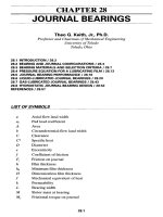
Electrical engineers have generally agreed on the line conventions that represent
wires, cables, conduit, and wiring within conduit, as illustrated in Fig. 1-1. For exam-
ple, branch circuit power wiring is represented as a solid line, while both switched
and control wiring are represented by broken lines. Abbreviations inserted within
breaks in the lines, such as “EM” for emergency and “CT” for cable tray, identify
their functions. Home runs from electrical devices to panels are represented as lines
with arrowheads.
However, there is no enforcement of generally acceptable line drawing standards
within the industry. Unless the draftsperson is required to follow a company style or
style is mandated by the client, there are many possible variations of the line samples
shown in the figure. For example, some drawings show branch circuit wiring as heavy
lines and control wiring as fine lines.
10 PLANNING FOR ELECTRICAL DESIGN
Figure 1-1 Lines used to indicate wiring on electrical drawings.
Ch01_Sclater_1377514 3/27/03 2:31 PM Page 10
Also, in some drawings the number of wires in a cable or conduit is indicated by
short diagonal slashmarks made through the line. This convention might be followed
only if there are more than three wires. In other schemes, wire gauge is indicated by
numbers positioned above or below the slashmarks.
A properly prepared drawing will include a key of symbols that explains the mean-
ings of all of the lines and symbols. Reference should always be made to this key to
verify the meanings of lines and symbols before trying to interpret the drawing.
Electrical Graphic Symbols
Electrical engineers and designers generally follow accepted standards for the basic
electrical and electronic symbols. These electrical symbols can be classified as those
used on connection and interconnection diagrams and those used on elementary or
schematic diagrams.
Connection and interconnection symbols represent complete electrical devices such
as switch outlets, receptacle outlets, lighting fixtures or luminaires, and auxiliary sys-
tems. These symbols take the form of relatively simple geometric shapes modified
with lines and letters inside or outside of them. The intent was to create a kind of tech-
nical shorhand that could be easily learned. They were kept simple to reduce the time
and expense of preparing drawings, particularly those used in the field for installation
of common off-the-shelf electrical components.
Figure 1-2 includes a selection of electrical connection and interconnection symbols
recommended by the American National Standards Institute (ANSI) for use on architec-
tural drawings. These symbols, or modified versions of them, are widely used on elec-
trical drawings in North America. Appendix A also includes a page of these symbols.
CAD electrical drafting software has eliminated the chore of reproducing these
symbols. The software contains a library of symbols that can be accessed from a
menu, downloaded, and dragged into position on the face of the screen as needed. The
basic symbols can be modified to fulfill special requirements or identify devices not
listed in the standard symbol list. In the past, symbols were usually drawn by the
draftsperson tracing around the inside of geometric cutouts in templates made of sheet
plastic.
As with line conventions, the motivation for using standardized symbols is to elim-
inate the time involved in trying to interpret drawings that include unfamiliar propri-
etary symbols. It is important that the symbols be easily recognized by all parties
involved in an electrical project, from the designer to the electricians doing the work.
As a result, the chances of making costly mistakes in interpretation are lessened.
Moreover, large architectural and consulting engineering firms with national and
international clients approve of symbol standardization because of the many people of
different backgrounds, languages, and cultures who could be using the drawings. This
is especially true of large-scale new construction projects such as hospitals, power sta-
tions, and industrial plants involving many different contractors.
ELECTRICAL GRAPHIC SYMBOLS 11
Ch01_Sclater_1377514 3/27/03 2:31 PM Page 11
As a condition of accepting a contract, many government agencies and large corpo-
rations require that drawings and specifications meet their standards. They provide
architectural and engineering design firms and eligible contractors with copies of their
documentation and drawing standards before any work is done. U.S. government agen-
cies including the Department of Defense (DoD), the National Aeronautics and Space
Administration (NASA), and the National Security Agency (NSA) each issue their
own drawing and specification standards.
12 PLANNING FOR ELECTRICAL DESIGN
Figure 1-2 Graphic symbols for electrical wiring diagrams.
Ch01_Sclater_1377514 3/27/03 2:31 PM Page 12
ELECTRICAL CONNECTION AND INTERCONNECTION
SYMBOLS
It can be seen in Fig. 1-2 that the basic symbol for the single-pole switch classed under
“switch outlets” is the letter “S,” but the symbol can be modified to represent other
switches by adding number or letter subscripts to indicate switch outlets such as dou-
ble-pole, three-way, and four-way, or functions such as pilot light, thermostat, timer,
and ceiling pull switch.
A circle intersected by a horizontal line is the symbol for a single grounded recep-
tacle in the “receptacle outlets” category. By adding additional lines to represent the
number of outlets, the single-receptacle symbol becomes the symbol for duplex,
triplex, and fourplex receptacles. Also, by adding letter abbreviations for special func-
tions such as range, and ground-fault circuit interrupter (GFCI), symbols for other
receptacles are obtained. If the receptacles are ungrounded, they are followed by the
letters “UNG.”
In a similar manner, the basic symbol for a luminaire in the “lighting outlets” cate-
gory is a plain circle, but adding a short line projecting to the left makes it a wall-
mounted luminaire. Here again, letters within the circle, such as “X” or “J,” represent
functions such as exit and junction.
Most of the symbols in the “auxiliary systems” or “residential occupancies” cate-
gory are based on the square, but some are based on circles. Here again, letters can be
used within the symbol, such as “TV” to represent a television jack and “CH” to rep-
resent a chime. Other symbols in this group include those for bells, buzzers, smoke
detectors, telephone outlets, pushbuttons, and ceiling fans.
In the case of luminaire symbols, schedules either on the drawing or within the writ-
ten specifications provide supplementary information about that luminaire, including
the name of the manufacturer, its catalog number, the type of lamp to be installed, volt-
age, finish, and mounting method.
Symbols for many of the objects are drawn in sizes that approximate the size of the
actual object drawn to the same scale as the architectural floor plan. They are accu-
rately located on the floor plan with respect to the building configuration, walls, doors,
windows, etc. Where extreme accuracy is required in locating outlets, luminaires, or
electrically powered equipment, exact dimensions are given from reference points on
the floor plans, such as height above the finished floor line or distance to the nearest
finished wall.
The key of symbols previously mentioned identifies the symbols and all included
internal letters or letter and number subscripts. There are also graphic symbols for
distribution centers, panelboards, transformers, and safety switches not shown here.
Unless mandated by contract requirements, the designer is free to modify standard
symbols as desired, provided that they are identified in the key of symbols or other
contract documentation. A detailed description of the service equipment on a pro-
ject is usually given in the panelboard schedule or in the written specifications.
However, on small projects the service equipment might be identified only by notes
on the drawing.
Appendix A includes a compilation of these ANSI architectural symbols.
ELECTRICAL GRAPHIC SYMBOLS 13
Ch01_Sclater_1377514 3/27/03 2:31 PM Page 13
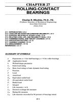
ELECTRICAL SCHEMATIC SYMBOLS
Another group of symbols, called elementary or schematic symbols, is used on elec-
trical one-line and schematic drawings. A selection of these symbols is shown in Fig.
1-3. Electrical schematic symbols are used in drawing circuits such as those for motor
starters or the wiring inside appliances or building service equipment.
14 PLANNING FOR ELECTRICAL DESIGN
Figure 1-3 Graphic symbols for electrical schematics, Part 1.
Ch01_Sclater_1377514 3/27/03 2:32 PM Page 14
Electricians installing equipment in the field might work with electrical schematic
diagrams if it is necessary to make specific connections inside an appliance or to hook
up a motor for a furnace, hot water heater, fan, compressor, pump, or other machine.
There are graphic symbols for all of the basic components in an electrical circuit,
such as capacitors, fuses, motors, meters, resistors, switches, and transformers. These
symbols are generally pictorial representations of the electrical functions performed
by the components. Most of these symbols were first used near the end of the nine-
teenth century, well before electronics was considered a separate technology, but the
set of standard symbols has been modified over the intervening years.
During World War II the U.S. Navy and War departments ordered the simplification
of some of the symbols to speed up the manual preparation of drawings for military
procurement. These were later made standards by the U.S. Department of Defense. For
example, the loops in the symbols for windings or coils that were standard on prewar
electrical drawing for inductors and transformers were replaced by easier-to-draw
scalloped lines. However, these obsolete symbols can still be seen in some textbooks
and equipment manufacturers’ catalogs. There is less uniformity in the depiction and
use of standard electrical schematic symbols in manufacturers’ catalogs and installa-
tion and maintenance diagrams because many of the older, well-established electrical
equipment manufacturers still favor the traditional symbols.
Some of the basic symbols are described below.
■
Battery: The multicell battery symbol is a set of long thin and short thick parallel
line segments representing poles, as shown in Fig. 1-3a. It is used on both electri-
cal and electronic schematics in North America. The plus sign next to the long seg-
ment identifies the positive pole.
■
Capacitor: The capacitor symbol used in both electrical and electronic schematics
is a straight line segment next to a curved line segment, as shown in Fig. 1-3b.
■
Circuit breakers: The symbol for both thermal and thermal-magnetic circuit break-
ers rated for less than 600 V is a semicircle positioned over a gap between the ends
of two conductors, as shown in Fig. 1-3c. The symbol for higher-rated circuit break-
ers, such as the oil-immersed units in distribution substations, is a square contain-
ing the letters “CB,” also shown in the figure.
■
Inductors or windings: The modern symbol for an inductor or winding is a scal-
loped line used to signify a single winding, as shown in Fig. 1-3d. If the inductor
has a ferromagnetic core, two parallel lines are drawn next to the scalloped line, as
shown in the same figure. However, some one-line electrical diagrams still use
zigzag lines as symbols for inductors.
■
Fuses: In electrical drawings, the fuse symbol is either a rectangle with bands at
each end, as shown in Fig. 1-3e, or a sine-wave curve, also shown in the figure. The
latter symbol, however, is more commonly seen on electronic schematics.
■
Ground connection: Three parallel line segments of diminishing length intersected
by a vertical line representing the conductor, as shown in Fig. 1-3f, is the symbol
for an earth ground. This symbol is also used on electronic schematics.
■
Lamps: The schematic symbol for a lamp can be a circle with four radiating line seg-
ments 90° apart, as shown in Fig. 1-3g. These could include a “W” for white or an
ELECTRICAL GRAPHIC SYMBOLS 15
Ch01_Sclater_1377514 3/27/03 2:32 PM Page 15
“R” for red, with the designation “PL” for pilot light. An alternative is a circle with
a cross inside.
■
Meters: The basic meter symbol is a circle; an “A” inside represents an ammeter, a
“V” a voltmeter, and a “W” a wattmeter, as shown in Fig. 1-3h.
■
DC motors: There are many different symbols for motors, the most basic being a
circle representing the frame and the letter “M” inside. The type of motor must be
determined from the context of the drawing. Common variations for DC motors
include circles with marks representing brushes or circles with the horsepower rat-
ings within the circle, as shown in Fig. 1-3i. DC motors have also been represented
by a circle with the letters “Arm” inside to designate an armature, with the symbol
for a series or field winding attached.
■
AC motors: The basic symbol for a single-phase AC motor is a circle with two pro-
jecting line segments, while a three-phase motor symbol is a circle with three line
segments. The symbols for three-phase synchronous and induction AC motors are
shown in Fig. 1-3j.
■
Generator: The generator symbol is a circle with a “G” inside and two tangent lines
representing brushes, as shown in Fig. 1-3k.
Note: It is common practice to provide additional information on motors and gen-
erators in a schedule on the drawing. This includes identification of the manufactur-
er, type, and horsepower rating for a motor or output voltage rating for a generator.
■
Resistors and rheostats: A rectangle with line segments projecting from each end,
as shown in Fig. 1-3l, is the most commonly used symbol for a resistor on electri-
cal schematics. The symbol for a rheostat, variable resistor, or potentiometer on
electrical schematics is shown in Fig. 1-3m. It represents a movable contact or
wiper on a curved resistive element.
■
Switches: Four different switch symbols commonly used on electrical schematics
are shown in Fig. 1-3n. The single-throw knife switch symbol is a line representing
a pole connected at one end to a conductor and offset so that when closed it will
bridge the gap to complete the circuit. The double-throw knife switch symbol is two
single-throw switches in parallel, with their poles connected. The normally open
(N.O.) pushbutton switch symbol is an inverted T-shaped pole above a gap between
two conductors, and a normally closed (N.C.) pushbutton switch has its pole bridg-
ing the gap between two conductors, completing the circuit. These symbols are also
used on electronic schematics.
■
Transformers: The basic electrical symbol for a transformer is a parallel pair of scal-
loped lines representing windings, but the symbol for a transformer with an iron core
(or steel laminations) has two parallel lines between the windings, as shown in Fig.
1-3o. Other symbols in the figure are those for current and potential or voltage trans-
formers. However, the zigzag symbol is still widely used on electrical one-line draw-
ings to represent a transformer. An autotransformer or single-winding transformer is
represented as a single winding with several taps, as shown in the figure.
■
Circuit breaker configurations: Two or more circuit breaker poles can be organized
to open or close simultaneously, as shown in Fig. 1-4a. Circuit breakers with ther-
mal trip units (thermal overloads) are represented as having conjoined C-shaped
16 PLANNING FOR ELECTRICAL DESIGN
Ch01_Sclater_1377514 3/27/03 2:32 PM Page 16
elements connected to one conductor, and those with magnetic trip coils (protective
relays) are represented as Z-shaped elements connected to one conductor.
■
Limit switch positions: Limit switch symbols are drawn as parallel lines or as
modified switch symbols, as shown in Fig. 1-4b. Both “normally open” (N.O.)
and “normally closed” (N.C.) limit switch symbols are illustrated.
ELECTRICAL GRAPHIC SYMBOLS 17
Figure 1-4 Graphic symbols for electrical schematics, Part 2.
Ch01_Sclater_1377514 3/27/03 2:32 PM Page 17
■
Contactor states (for limit switches and relays): The parallel line symbol for a con-
tactor, as shown in Fig. 1-4c, is widely used in electrical schematic drawings and
logic diagrams. A gap between the lines indicates that they are normally open
(N.O.), but a diagonal line across the symbol indicates that they are normally closed
(N.C.). The letters “TC” adjacent to the symbol indicate “time-delay closing,” while
the letters “TO” indicate “time-delay opening.” Alternative symbols for contactors
with equivalent meanings shown here are modifications of the standard knife
switch symbol.
■
Contactor symbols on schematic drawings are usually accompanied by the symbol
for a coil, a circle enclosing a letter “C.”
Electronic Graphic Symbols
Before the turn of the twentieth century the electrical industry was engaged in the
manufacture and installation of equipment for DC and AC power generation and light-
ing, and transmission, and distribution, is still very much its role today. At that time
there were also separate telegraphy and telephony industries. The Atlantic Cable was
functioning, and there were practical telegraph systems and telephone companies in
the advanced Western countries. However, about that time experiments demonstrated
that wireless telegraphy was practical, and after Guglielmo Marconi sent a wireless
signal across the Atlantic in December 1901, the radio industry was born.
The early radio industry focused on the design and manufacture of components and
equipment for transmitting and receiving radio signals. Although it was a spinoff of
the electrical power industry and depended on the same electrical laws and measure-
ment instruments as well as many of the same components, it developed as a separate
industry with no links to the power, telephone, or telegraph industries.
After World War II the radio industry evolved into what is now known as the elec-
tronics industry, which has expanded to include computers and computer science.
From its origins in the development of vacuum tubes and their application in rectifiers,
detectors, amplifiers, and radio transmitting and receiving equipment, it went on to
produce semiconductor devices and integrated circuits.
It was not long before the benefits of electronics in terms or reliability, low power
consumption, and versatility attracted the attention of the electrical power industry,
which began to incorporate electronic devices and circuits into its equipment. This
brought the electrical power and electronics industries closer together.
Soon electromechanical rectifiers were replaced by solid-state rectifiers, electronic
instruments replaced moving-coil instruments, and in many applications solid-state
electronic relays began to replace electromechanical relays.
Today the electronic/computer industry has a close cooperative relationship with the
electrical power industry. Electronic ballasts are replacing magnetic ballasts for fluorescent
lamps, and solid-state circuits have made possible such products as dimmers, GFCI cir-
cuits, occupancy sensors, and surge protectors. Microcontrollers have also replaced banks
of relays for the control of a wide range of appliances, machines, and motion controllers.
18 PLANNING FOR ELECTRICAL DESIGN
Ch01_Sclater_1377514 3/27/03 2:32 PM Page 18
Despite this close tie between electronics and electrical power, it is still possible
for an electrician or electrical contractor to perform his or her work without train-
ing in electronics; however, that situation is fast changing, due in large part to
deregulation of both the telephone and electrical power industries. A working
knowledge of electronics is now considered to be an essential part of the training
for electrical contractors and electricians as well as electrical equipment and main-
tenance personnel.
As discussed earlier, many of the original electrical symbols have been adopted by
the electronics industry for use on electronic schematics. They include symbols for the
battery, capacitor, earth ground, lamp, and transformer. However, a new set of spe-
cialized radio (and later television) symbols had to be developed to represent compo-
nents not found in electrical power circuits. These include antennas, cathode-ray tubes,
headphones, speakers, radio-frequency coils, crystals, and receiving tubes. Later, new
symbols were developed for thyratrons, magnetrons, klystrons, traveling-wave tubes,
solar cells, transistors, and integrated circuits.
Figure 1-5 illustrates some of the more commonly used electronic symbols that are
likely to appear on schematics for the rectification, amplification, and control of power.
Electronics schematics identify each symbol with an alphanumeric code and rating
information near the symbol. For example, batteries are rated in volts, capacitors in
microfarads, inductors in microhenries, and resistors in ohms.
■
Batteries: The multicell battery symbol shown in Fig. 1-5a is common to both elec-
trical and electronic drawings. The symbol for a single cell (also called a battery) is
more commonly found on electronic schematics. Batteries are identified on elec-
tronic schematics as B1, B2, etc.
■
Capacitors: Electronic schematics distinguish between various types of capacitors,
as shown in Fig. 1-5b. The symbol for the variable capacitor has an arrow through
it, and the symbol for the electrolytic capacitor has a plus sign above it to indicate
its polarization. Capacitors are identified on electronic schematics as C1, C2, etc.,
and their values in microfarads (F) are usually given.
■
Inductors: Electronic schematics use the same symbols for windings, coils, or
inductors as electrical schematics, as shown in Fig. 1-5c. Inductors are identified
on electronic schematics as L1, L2, etc.
■
Diodes: The diode symbol in electronic schematics is an arrowhead pointing to the
flow of conventional current, as shown in Fig. 1-5d. Electronic schematics include
many different variations on this basic symbol to represent zener diodes, light-emitting
diodes (LEDs), and thyristors. The outward-directed arrows on the LED symbol
represent emitted light. Diodes on electrical schematics are identified as D1, D2,
etc., but LEDs are identified as LED1, LED2, etc.
■
Fuses: The electronic symbol for a fuse is a sine-wave shape, as shown in Fig. 1-
5e. Fuses are identified on electronic schematics as F1, F2, etc.
■
Ground: Electronic schematics use the same ground symbol as electrical schemat-
ics, as shown in Fig. 1-5f.
■
Integrated circuits (ICs): The symbol for an integrated circuit is a rectangle with
the projecting lines representing its pins, as shown in Fig. 1-5g. It is a pictorial
ELECTRONIC GRAPHIC SYMBOLS 19
Ch01_Sclater_1377514 3/27/03 2:32 PM Page 19
representation of a rectangular IC package as viewed from the top. The notch at one
end indicates the starting point for pin numbering. The first pin is on the upper right
corner and numbering continues counterclockwise around the device, with the last
pin at the lower right corner. This information is important for orienting the IC cor-
rectly in a circuit. ICs are identified as IC1, IC2, etc. They might also be identified
20 PLANNING FOR ELECTRICAL DESIGN
Figure 1-5 Graphic symbols for electronic schematics.
Ch01_Sclater_1377514 3/27/03 2:32 PM Page 20
with industry standard type numbers such as 555 or 7447, or a manufacturer’s numer-
ical designation such as CD4040. The most advanced and fastest microprocessors are
also represented by this symbol, but they will have many more pins than most ICs.
■
Thyristors: The symbol for the most common half-wave thyristor, the SCR (for sil-
icon controlled rectifier), and the triac are shown in Fig. 1-5h. They are three-ter-
minal variations on the basic diode symbol.
■
Transistors: Figure 1-5i shows the symbols for typical discrete power transistors
that are widely used in electrical control systems. Other symbols have been devel-
oped for various field-effect transistors (FETs). The MOSFET and power MOSFET
symbols are shown here. On electronic schematics transistors are identified as Q1,
Q2, etc. They are also marked with an industry standard number or the manufac-
turer’s proprietary designation.
■
Rectifier bridges: A configuration of four rectifier diodes, as shown in Fig. 1-5j, is
called a bridge. Bridges are widely used in electrical equipment for rectifying full-
wave AC. Bridges are identified on electronic schematics as BR1, BR2, etc.
■
Relay: The electronic schematic relay symbols shown in Fig. 1-5k are more detailed
than the relay symbols shown on electrical schematics. The rectangle above the
relay contacts represents a solenoid. In this example the contacts are normally open
(N.O.). When the solenoid is energized, the contacts will close. Relays are identi-
fied on electronic schematics as RY1, RY2, etc.
■
Resistors: The zigzag line symbol in Fig. 1-5l is the one accepted for U.S. electronic
schematics. The variable resistor or potentiometer symbol is the resistor symbol
with an arrow at right angles to indicate a movable contact. Resistors are identified
as R1, R2, etc., and the value in ohms is usually given.
■
Switches: The electronic symbols for switches shown in Fig. 1-5m are the same as
those used on electrical schematics. Switches on electronic schematics are identi-
fied as S1, S2, etc.
■
Transformers: The symbols for transformers, as shown in Fig. 1-5n, are basically
the same the same as those used on electrical schematics. Transformers are identi-
fied on electronic schematics as T1, T2, etc.
Drawing Schedules
Drawing schedules are systematic listings of equipment in tabular form accompanied
by identification notes. They provide information about the components and equip-
ment shown as symbols on the drawings. Schedules typically are placed on one-line
drawings, wiring diagrams, and riser drawings.
Schedules on drawing sheets are more convenient for the use of field supervisors,
electricians, and installers than separate specification pages that could be easily lost or
misplaced in the field, and they save time required to find the information on separate
pages. Also, when the schedules are on the related drawings, the draftsperson is better
able to coordinate the symbols with the supporting information. This simplifies mak-
ing changes and assures data accuracy without having to cross-reference other sources.
DRAWING SCHEDULES 21
Ch01_Sclater_1377514 3/27/03 2:32 PM Page 21