Tài liệu Handbook of Electrical Design Details P2 pptx
Bạn đang xem bản rút gọn của tài liệu. Xem và tải ngay bản đầy đủ của tài liệu tại đây (280.99 KB, 20 trang )
the motor it will control. The contactors, overcurrent protective devices, transformer,
and operating coil are in one enclosure, and the start/stop pushbuttons are in a sepa-
rate enclosure so that they can be mounted some distance from the motor.
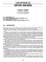
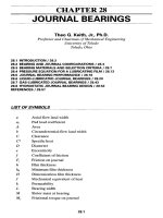
In this schematic each component is represented by a graphic symbol, and each wire
is shown making individual connections between the devices. However, multiple wires
could appear as one line on the drawing. As on this drawing, each wire is usually num-
bered to indicate where it enters the enclosure, and those numbers are repeated for the
same wires connected inside the enclosure.
The three supply wires are identified as L1, L2, and L3; the motor terminals are des-
ignated T1, T2, and T3; and the normally open line contactors controlled by the mag-
netic starter coil C are designated as C1, C2, and C3. Each contactor has a pair of
contacts that open or close for control of the motor.
The remote control station consists of the stop and start pushbuttons connected across
lines L1 and L2 by the primary of an isolation control transformer. The transformer sec-
ondary in the control circuit is in series with the normally closed overload contactors
(OC) and the magnetic starter coil (C). The stop button is also connected in series with
the starter coil, and the start button is connected in parallel with the starter coil.
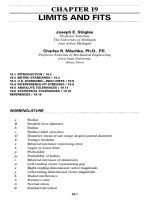
ELECTRICAL PROJECT DRAWINGS 27
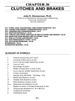
Figure 1-8 Power riser diagram for a combined office-warehouse building.
Ch01_Sclater_1377514 3/27/03 2:32 PM Page 27
In this circuit, the control transformer isolates the control circuit and prevents it
from responding to any ground faults that could cause the motor to start accidentally.
The isolating transformer can have its primary winding identical to its secondary
winding so that input voltage equals output voltage, or it can step the motor circuit
voltage down to a lower level as an added safety measure for the control circuit.
ELECTRICAL DETAIL DRAWINGS
Electrical detail drawings are prepared as separate sheets to give the installer more
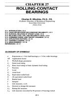
complete details of a specific, nonstandard installation requirement. Figure 1-10 is a
detail drawing of a section through the wall of an office warehouse. It provides details
of how and where hanger fittings and boxes are to be placed between a column and
insulation to support a run of bus duct.
Any set of electrical drawings might require additional “blowup” drawings of certain
technical details that are not clearly indicated on small-scale drawings, particularly plan
views. In this example, it is an elevation view of a section wall shown on a plan view. It
includes both mechanical and architectural details. Other drawings might show section
views of special foundations or footings, or suspension systems for electrical equipment.
These detail drawings might be drawn by the consulting architectural or engineer-
ing firm on complex projects, but they might also be supplied by the manufacturer of
the equipment or hardware to be installed. The consulting firm will collate these draw-
ings into the related set with appropriate sheet numbers.
28 PLANNING FOR ELECTRICAL DESIGN
Figure 1-9 Schematic diagram for an across-the-line motor starter.
Ch01_Sclater_1377514 3/27/03 2:32 PM Page 28
SHOP DRAWINGS
Many items of electrical equipment such as motors and motor control cabinets are
standardized by the manufacturer, and the outline and footprint dimensions are includ-
ed in their catalogs. However, large, costly electrical equipment such as high-voltage
switchgear, transformers, motor control centers, HVAC (heating, ventilating, and air
conditioning) systems, and elevators are usually custom made for each project. Project
shop drawings for this equipment are usually drawn by the manufacturer and furnished
prior to the delivery of the equipment. They might also include installation and main-
tenance manuals custom-prepared for the specific project.
The architect/engineer requires dimensional outline information to lay out the loca-
tion of the equipment on the elevation drawings and check for any possible interfer-
ence conflicts that could develop. For example, the equipment must be positioned to
provide, safe easy access to the equipment for routine maintenance. Allowance must
be made for the swing radii of all doors, and adequate space must be allowed for main-
tenance personnel to gain access to the equipment through removable cover panels as
well as enough room to work.
ELECTRICAL PROJECT DRAWINGS 29
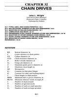
Exterior paneling
Insulation
Girt
Top and
bottom nuts
3
/
8
" threaded
rod
Column
Hanger
Busway section
(secure against
column)
24"
Figure 1-10 Electrical con-
struction detail for hanging a
busway.
Ch01_Sclater_1377514 3/27/03 2:32 PM Page 29
In some cases, special concrete footings must be prepared with specified lag bolts for
anchoring the equipment before it is delivered. This work must be completed and the con-
crete must be sufficiently cured to accept the load when the equipment arrives on the site.
Shop drawings also are helpful for the contractor responsible for installing heavy
equipment, so any required cranes or other heavy moving equipment will be on the site
prior to the delivery of the equipment. In addition, the contractor must make sure that
any existing openings in the walls or doorways are wide and high enough to provide
adequate clearance for the entry of the equipment. Advance information will give the
contractor enough time to install any conduit, cable trays, or plumbing that would be
difficult or excessively costly to install after the equipment is in place.
As-built drawings that include detailed “factory-wired” connection diagrams will
assist the installer in performing any “field wiring.” Later they will be important if any
commissioning procedures or final acceptance testing is required. These drawings will
then become part of a maintenance file to assist the maintenance personnel in the per-
formance of any troubleshooting that might be required at a later date, after the equip-
ment is operational. These drawings and any operation and maintenance manuals are
essential documents of record that will be useful for making any later additions to the
facility.
Electrical Product and Work Standards
The generation, transmission, and distribution of electrical power are now deregulated,
but many rules, regulations, and standards still apply to the manufacture of electrical
equipment, the job site, and the installation of electrical systems. Many of these stan-
dards are focused on safety issues, such as the elimination or avoidance of hazards in
working with or using electricity.
The installation of any inferior wiring devices or equipment, substandard work-
manship, or inadequate test and maintenance procedures could be the cause of fires or
explosions and result in the creation of electric shock hazards. There is a need for
standards that, when adopted, will serve as a basis for proper inspection and supervi-
sion. There are regulatory standards, national consensus standards, product standards,
installation standards, and international standards.
The consensus standards include the
National Electrical Code (NEC), the National
Electrical Safety Code (NESC), National Fire Protection Association (NFPA) 70B and
70E, and other NFPA standards, as well as American National Standards Institute
(ANSI) and the Institute of Electrical and Electronic Engineers (IEEE) standards.
Interested persons with requisite education, training, and background experience vol-
unteer their time and expertise to develop these standards. Some might be employees
of electrical product manufacturers, and others might be consultants or engineering
professors.
Some standards were developed specifically for electrical applications. These
include the
National Electrical Code (NEC) (officially NFPA 70) and the National
30 PLANNING FOR ELECTRICAL DESIGN
Ch01_Sclater_1377514 3/27/03 2:32 PM Page 30
Electrical Installation Standards (NEIS). In addition, the National Electrical
Manufacturers Association (NEMA) standards cover equipment design and construc-
tion, while the Underwriters Laboratories Inc. (UL) standards cover safety provisions
in the manufacture of electrical devices, products, and accessories.
The National Fire Protection Association (NFPA), publisher of both the
NEC and
NESC, has also developed standards related to electrical work including:
■
NFPA 79 Industrial Machinery
■
NFPA 780 Lightning Protection
■
NFPA Static Electricity
The NFPA has also developed standards for fire prevention, installation of sprin-
klers, stacking materials, and a standard building code. The following organizations
have also developed standards that have a bearing on electrical work:
■
ACS: American Chemical Society
■
ACGIH: American Conference of Governmental Industrial Hygienists
■
AIChE: American Institute of Chemical Engineers
■
ASME: American Society of Mechanical Engineers
■
ASTM: American Society for Testing and Materials
■
ASSE: American Society of Safety Engineers
■
AWS: American Welding Society
■
CGA: Compressed Gas Association
■
CMA: Chemical Manufacturing Association
■
CMAA: Crane Manufacturer’s Association
■
GSA: General Services Administration Federal Supply Services
■
NSC: National Safety Council
■
OSHA: Occupational Safety and Health Administration
Individuals or organizations with a professional or business interest in these stan-
dards can join these organizations to help support them and gain access to their
newsletters so that they can stay informed on any changes within the standards.
Standards-making organizations may make changes to their standards between nor-
mal cycles that are not included in the printed text of the original issue of the standard.
The NFPA, for example, does this in the form of a Tentative Interim Amendment
(TIA). Additionally, changes may take place without a formal notice of change, so it
is important to stay current with any given standard. Interested parties can communi-
cate with these standards organizations and suggest changes or revisions in standards.
It is the responsibility of all electrical contractors, electricians, and installers in the
field to know which standards apply to any project taking place within any given
location or job site. It is also important to remember that not all standards that might
apply to every job site or location actually apply. A hazard assessment by the project
supervisor or licensed electrician must determine which standards apply at each
workplace and that they are followed.
ELECTRICAL PRODUCT AND WORK STANDARDS 31
Ch01_Sclater_1377514 3/27/03 2:32 PM Page 31
The contractor has the responsibility for assuring that a workplace is free from rec-
ognized hazards and is a safe place for electricians and installers to work. This could
apply to such factors as the quality of ladders or scaffolding at the site or the need for
safety goggles or face masks when performing certain kinds of work. For example, eye
protection should be worn during any grinding or cutting operations that could result
in flying chips of metal, and proper face masks should be worn by anyone performing
burning or welding that could result in the release of toxic gases.
Designers, engineers, contractors, electricians, or equipment installers and all other
persons whose work is governed by one or more standards should be familiar with and
know how to apply the rules found in all of the applicable standards. These are the rules
that relate to design, including safety considerations, for a particular project or task.
What Are Electrical Specifications?
Electrical specifications for buildings or projects are written legal descriptions of the
work to be performed by the electrical contractor, subcontractors, and electric power
utilities and the responsibilities and duties of the architect/engineer, general contrac-
tor, and owner. Electrical specifications and electrical drawings are integral parts of
the contract requirements for the performance of electrical work.
Because specifications are a significant part of a legally binding contract, typically
involving expenditures of thousands or even millions of dollars, it is important that
they be mutually compatible with the drawings and as free as possible of errors or dis-
crepancies. It has long been known that even minor errors in wording or intent or the
presentation of incorrect data or measurements can result in expensive repairs or
replacements of hardware, lost time in the completion of the schedule, and serious
project cost overruns due to delays and the need for additional labor and supervision.
In most engineering and architectural firms, regardless of size, specifications writers
are skilled persons with technical backgrounds who report to a responsible project super-
visor. The preparation of an error-free specification is a time-consuming task calling for
the writer’s patience and the ability to deal effectively with complex technical details. The
process might call for many drafts and revisions following the review, comments, and cor-
rections made by persons within the architect/engineering organization with specialized
knowledge and experience in each of the trades involved in the project. As with drawings,
all responsible reviewers are expected to sign the final version that is released for bid.
Nevertheless, this does not relieve specifications writers of their responsibilities,
because they are expected to have sufficient knowledge of the project to make them
capable of finding and resolving any discrepancies between the specifications and the
drawings. Discrepancies are most likely to occur when
■
A generic master or prototype specification is used without making all of the mod-
ifications necessary to reflect what is actually shown on the working drawings.
■
Revisions that should have been made in a previously prepared drawings are indi-
cated only by a note in the revision block, leaving the drawing unchanged.
32 PLANNING FOR ELECTRICAL DESIGN
Ch01_Sclater_1377514 3/27/03 2:32 PM Page 32
■
Revisions in items that are listed both in schedules on the drawings and in the writ-
ten specifications are made on only one of these documents.
For example, there is a discrepancy if the specification calls for one loadcenter but the
drawing has been revised to show two loadcenters and this change is not reflected back
to the specifications. Such a discrepancy could result in unnecessary costs, unless
caught in time. For this reason, it is not good professional practice to duplicate the same
information on both specifications and drawings. It is preferable that the required infor-
mation be placed on the document on which it is most logically found to assure com-
pliance, with perhaps a reference to its location on the other document.
If for some reason duplication of information occurs in both drawings and specifi-
cations, and it is not practical to delete it from one of the documents, the project super-
visor should add a note to the contract before it is put out for bid stating whether the
specifications or drawings take precedence.
THE MASTER ELECTRICAL SPECIFICATION
Appendix B is a sample master electrical specification edited specifically for electri-
cal work to be done in a new residence or small office. It is intended for educational
purposes only and should not be used as the basis for an actual contract specification
unless reviewed and approved by a licensed electrical contractor or specialist in elec-
trical power and lighting specifications.
A master specification, regardless of its source, is a generic prototype or template that
functions both as a check-off list and repository of useful paragraphs from which a speci-
fications writer can pick and choose to prepare a working specification. Those paragraphs
that do not relate to the project can be deleted and new or revised paragraphs can be added.
The master specification is written in a quasi-legal style with words such as shall,
will, and may having very specific meanings. Shall, for example, indicates that the
party named must carry out the specified activity; will indicates that there is certain-
ty that the party named will perform the specified action; and may means that per-
mission can be granted for the party named to take a specific action. Some phrases
widely used in specifications to convey specific meaning are or equivalent, as
approved, and unless otherwise specified.
The master specification might be the result of years of accumulated experience of
an engineering or architectural firm, or it could be a document prepared by an indus-
try-sponsored institute based on the collective experience of its members. Regardless
of the specification’s origin, it is the specifications writer’s task to modify or “tailor”
it to fit a specific project. After all of the applicable general paragraphs have been
selected, they are supplemented with the additional information required to identify
the desired materials, equipment, products, and devices, and perhaps even specify the
methods or procedures required for the performance of the work.
It necessarily follows that implementing a master specification requires specialized
technical knowledge in the interpretation of drawings and practical experience or training
in a specific trade. Experience is also needed in knowing the optimum locations for pre-
senting certain kinds of information, either on the drawings or in the specification.
WHAT ARE ELECTRICAL SPECIFICATIONS? 33
Ch01_Sclater_1377514 3/27/03 2:32 PM Page 33
For many straightforward projects such as modifying or updating the electrical sys-
tem in a residence, small office building, or retail shop, a simple one-page specifica-
tion or description of the work to be done may be sufficient to describe the scope of
the work. However, it might also have one or two working drawings attached, if nec-
essary. By contrast, large-scale commercial or industrial projects might require hun-
dreds of pages of specifications and hundreds of working drawings.
Master specifications are also prepared for the work of other trades such as masonry,
carpentry, structural steel work, plumbing, and machine or mechanical equipment instal-
lation. Each of these divisions in a general specification is organized in a manner simi-
lar to the electrical division with certain provisions and special conditions common to
all. They also include paragraphs covering such topics as the type and quality of mate-
rials to be used, the equipment to be furnished, workmanship, and testing.
The general specification must deal with situations where the work of various trades
overlaps or is interdependent. This calls for precise definitions of work boundaries and
the responsibilities among subcontractors. It might also involve precise scheduling to
minimize worker downtime in one trade while the work of another trade is performed.
Master electrical specifications are typically organized in sections such as the
following.
General Provisions sections consist of a group of considerations and regulations
that apply to all sections of the division. Topics covered might include the scope of
work, electrical reference symbols, codes and fees, and tests to be performed.
Basic Electrical Material and Methods sections identify type and quality of materials,
equipment, and devices specified for use such as wiring and cable, conduit, boxes, cab-
inets, loadcenters, switches, receptacles, motors and starters, and overcurrent protective
devices. They might also specify methods for installing certain kinds of equipment.
Power Generation sections cover equipment used for emergency or standby power
generation that would take over essential electrical service during a utility power out-
age. They usually include installation requirements for emergency circuits, generator
sets, storage batteries, controls, and distribution switches.
Medium Voltage Distribution sections cover the installation of high-voltage (over-600-
V) transmission and distribution facilities required for large government or industrial
facilities, work that would not be performed by publicly held electric utilities because it
does not relate to their system operation. The equipment specified in these sections is
usually rated for more than 2.4 kV, and includes substations, switchgear, transformers,
rectifiers, converters, power factor-correction capacitors, and instrumentation.
Service and Distribution sections cover the distribution of power under 600 V for res-
idential, commercial, and light industry projects including service entrances, metering,
grounding, branch circuit loadcenters, and branch circuits including the size and num-
ber of conductors, wiring devices, circuit protection devices, and installation methods.
Lighting and Luminaires sections cover interior and exterior luminaires and lamps.
Schedules identify luminaire types and locations and the ratings, types, and number of
required lamps. These sections cover the requirements for indoor lighting, including such
topics as track and recessed lighting, emission colors of lamps, and types of ballasts. They
can also cover outdoor floodlighting and even street lighting, poles, and standards.
34 PLANNING FOR ELECTRICAL DESIGN
Ch01_Sclater_1377514 3/27/03 2:32 PM Page 34
Special Systems sections cover a wide variety of special systems related to or depen-
dent on electrical power. Examples include lightning and surge protection, battery
chargers, outdoor low-voltage lighting systems, and door chimes.
Communications sections cover such systems as fire alarm, burglar alarm, surveil-
lance, multimedia, public address, and intercommunication, as well as wiring for tele-
phone systems and cabling for cable and satellite TV systems.
Heating, Ventilation, and Air Conditioning sections cover the installation and wiring of
electric heating, ventilating, and air-conditioning equipment. Examples include ranges,
microwave ovens, washing machines, dryers, baseboard heaters, exhaust fans, and wall-
mounted air-conditioning units. The work of these sections requires cooperation between
mechanical equipment and appliance installers and the electrical contractor.
Controls sections cover controls and instrumentation installed on a project.
Examples include recording and indicating devices, interior low-voltage lighting con-
trol systems, thermostats, and remote HVAC controls.
PREPARING A WRITTEN SPECIFICATION
The preparation of an accurate and complete electrical specification is the responsi-
bility of the architect/engineer and is an integral part of the project contract docu-
mentation. The specification must be coordinated with the project electrical drawings,
and failure to do so can result in significant costs and lost time for making corrections.
The electrical specification for a project might refer to hundreds of products, parts, and
components as well as numerous items of equipment and systems. By agreement between
the owner and the architect/engineer, these items can be specified in different ways. They
can be approved only if they are the products of a single manufacturer and are identified by
a part or model number. Alternatively, the citation of one manufacturer and model num-
ber can become the standard for quality and specification grade (hospital, industrial,
commercial, or residential) if the phrase “or equivalent” is added. Yet another option is
simply the statement in the specification that a material or product shall conform to a spe-
cific commercial, federal, or military standard or comply with certain codes and tests.
In some specifications, especially those calling for the procurement of equipment or
systems, a summary of critical performance characteristics and perhaps outline
dimensions is included to define the desired products. This information can be
obtained from the catalog data obtained from a number of manufacturers whose prod-
ucts have been approved as meeting the specification requirements. By using this
approach, procurement is opened to competitive bidding from a wider base of quali-
fied suppliers. This can lead to more favorable prices and delivery schedules.
GENERAL AND SPECIAL CONDITIONS AND PROVISIONS
The General Conditions section of written specifications consists of a selected group of
regulations that apply to the general contractor as well as all subcontractors (electrical,
mechanical, structural, plumbing, etc.). The General Conditions are usually presented as
a formal standard document entitled General Conditions of the Contract for Construction.
WHAT ARE ELECTRICAL SPECIFICATIONS? 35
Ch01_Sclater_1377514 3/27/03 2:32 PM Page 35
Among the subjects covered in General Conditions are the bid, the required con-
tract, and performance bonds and insurance payments, as well as the identification of
those responsible for such duties as removing rubbish and providing temporary elec-
trical service. All of these subjects are of concern to the electrical contractor. The elec-
trical specification writer must make certain that nothing in the electrical specification
conflicts with these General Conditions.
Some project specifications include Supplementary General Conditions and Special
Conditions. These are inserted after the General Conditions, and they normally apply
only to the general contractor. However, if there is a requirement for Supplementary
General or Special Conditions that apply to only one trade, they are usually inserted
in the division of the specification that applies to that trade.
Electrical specifications typically include a General Provisions section that applies only
to that division. It is intended to remind those using the electrical specification that the
General and Special Conditions apply because they are also a part of the specification.
The General Provisions section typically includes paragraphs entitled Temporary
Power; Electrical Drawing and Symbols, including the requirement that a symbol list
appear either on the drawings or in the written specification; Work Included; Work Not
Included; and Codes and Fees. The Codes and Fees section states that the electrical
contractor must comply with all applicable codes, federal laws, state and local ordi-
nances, industry standards, electric utility specifications, and fire insurance require-
ments. It also includes a penalty clause to be invoked against the electrical contractor
for noncompliance.
Some electrical specifications include only a General Description of the Work or
Scope of the Work on the assumption that this will be sufficient because more detailed
information will follow in subsequent pages.
The sample master specification in App. B contains both Work Included and Work
Not Included sections. The latter section identifies the electrical equipment to be
■
Furnished, installed, and wired by others.
■
Furnished and installed by others, but wired by the electrical contractor.
■
Furnished by others, but installed and wired by the electrical contractor.
36 PLANNING FOR ELECTRICAL DESIGN
Ch01_Sclater_1377514 3/27/03 2:32 PM Page 36
POWER GENERATION AND
TRANSMISSION
CONTENTS AT A GLANCE
Overview
Energy for Electricity Generation
North American Power Grid
Single- versus Three-Phase Power
Power Generating Stations
AC Generators
Auxiliary Power Station Equipment
Generator Synchronization
Wye- and Delta-Connected Loads
AC Transmission Systems
Transmission Towers, Poles, and Frames
High-Voltage DC Transmission
Overview
The first commercial power plant was opened in San Francisco in 1879. It was fol-
lowed in 1882 by the opening of Thomas Edison’s Pearl Street station in New York
City, which delivered direct current (DC) electric power. In 1893 alternating current
(AC) generation and transmission were displayed at the Chicago Worlds Fair. By 1896
an AC transmission line had delivered power generated by a Niagara Falls hydroelec-
tric plant some 20 miles to Buffalo, New York. After a contentious battle between
Thomas Edison and other proponents of DC power, the advocates of AC power such
2
Ch02_Sclater_1377514 3/27/03 2:30 PM Page 37
Copyright 2003, 1997 by The McGraw-Hill Companies, Inc. Click Here for Terms of Use.
as Nikola Tesla and George Westinghouse prevailed. Alternating current became the
accepted national power standard. Demonstrations had proven that AC transmitted over
long distances sustained lower power losses than DC transmitted over the same distances.
Over the next hundred years a North American power grid, a major development in
power generation and transmission, evolved from the consolidation of separate AC
power generation and distribution networks. This grid now stretches across the coun-
try from New York to California, with parts extending into Canada and Mexico. More
recently, computer-controlled switching systems with advanced software have been
introduced into the power grid.
Meanwhile, electric power generating capacity has fallen behind the ever-increasing
demand for electricity in North America. The power shortage has been traced to the
complications brought on by deregulation, a shortfall in the construction of new power
plants, and strong environmental activism that has inhibited new plant construction.
The deregulation of the electric power industry in the 1990s has resulted in immense
changes in the industry since that time. While traditional electric utilities still gener-
ate, transmit, and distribute electricity much as they did before deregulation, many
others have taken advantage of deregulation to divest themselves of their power gen-
eration facilities, which had long served their local areas. Of these utilities, some
acquired newer, more efficient generation plants in other locations, while others aban-
doned generation altogether. Some utilities that gave up on generation claimed that
they wanted to concentrate their resources on transmission, distribution, and improv-
ing customer service, but others admitted that they just wanted to be free from the con-
stant public complaints about the air pollution produced by their power stations.
As a direct result of deregulation, the electric power industry has seen the entry into
the market of small and independent power producers, so-called merchant generators,
and power marketers. Moreover, there has been a significant increase in mergers and
acquisitions within the industry, along with the entry of some power utilities into other,
more lucrative commercial enterprises. The objective of some of this diversification
has been the formation of integrated energy services.
Power marketers act as independent middlemen who buy and sell electricity in the
wholesale market at market prices. Most of this power is traded in the growing elec-
tricity commodity market. In the past, power marketers did not own electric generation,
transmission, or distribution facilities, but recently even this has changed. They are now
acquiring generation plants under various ownership and leasing arrangements.
Electric utilities now bid for electricity from various generation plants in two auc-
tions, one that occurs every day before the power is scheduled for use and another that
happens an hour before use.
The U.S. electric power industry today is a complex mix of organizations consisting
primarily of shareholder-owned, cooperative-owned, and government-owned utilities
engaged in power generation, transmission, and distribution. There are, however, other
participants classed as nonutility producers and suppliers. As one of the nation’s
largest industries, the revenues generated by the U.S. electric power industry surpass
those of the telecommunications, airline, and natural gas industries.
Demand for electricity in the United States has historically been closely correlated
with economic growth. Since the end of World War II, electric power demand has
38 POWER GENERATION AND TRANSMISSION
Ch02_Sclater_1377514 3/27/03 2:30 PM Page 38
matched the growth in the gross domestic product (GDP), the indicator of economic
health. The reasons for this increasing demand for electricity include the population
expansion, the surge in the use of electrically powered labor-saving machines, tools,
and appliances, wider acceptance of air conditioning in all parts of the country, and
the popularity of home entertainment electronics and computers.
Newer models of TVs, stereo systems, and computers consume more power than
their predecessors, and the Internet has attracted nearly around-the-clock home com-
puter operation. Deregulation introduced competition and the price of electricity with
respect to the cost of living index has fallen, encouraging even more consumption.
The electric power industry recognizes three major customer groups: residential,
commercial, and industrial. As one might expect, the number of residential customers
far exceeds the number of commercial and industrial customers. The commercial cus-
tomer base includes retail stores, hotels, offices, and restaurants, but the ratio of cus-
tomers to the total sales of electricity is relatively small. The customer base in the
industrial sector is the smallest, accounting for less than 1 percent of all electric utility
customers. The sector consists primarily of large corporations engaged in manufac-
turing, mining, and the processing of oil, chemicals, metals, and food.
Surprisingly, each of these groups buys about one-third of the total power generated
in the United States. However, there is yet another smaller group of customers, not
classed among the big 3 because it consumes less than 3 percent of all electricity gen-
erated. This group includes railroads, national, state, and local government agencies,
and the state and municipal authorities that pay for street and highway lighting.
Energy for Electricity Generation
More than 85 percent of all electric power generated in North America is produced by
AC generators that are driven by steam turbines. Of this amount, more than 65 percent
of the steam is produced by burning of fossil fuels, primarily coal and natural gas. The
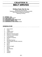
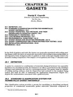
pie chart Fig. 2-1 illustrates the distribution of energy sources for electrical power gen-
eration in the United States. The proportions hold for North America and many
European countries as well.
Coal is the dominant fossil fuel consumed to produce steam, accounting for more
than 50 percent of all energy consumed. Despite its reputation as a constant threat to its
neighbors, nuclear energy accounts for only about 20 percent of the energy consumed
for electric power generation. The nuclear reactors function only as steam generators.
Natural gas is in third place among energy sources for steam generation. Oil is also
a fossil fuel accounting for only about 3 percent of the energy consumed for electric
generation, but most of it is used to power gas turbines in turbine generators or as fuel
for the diesel engines in engine–generator sets.
Coal remains the dominant fuel worldwide for producing the steam required for
electric power generation, despite efforts toward using the so-called renewable resources:
water power, wind power, and solar power. Coal retains its importance because it is
plentiful and relatively inexpensive and because many industrialized countries have
ENERGY FOR ELECTRICITY GENERATION 39
Ch02_Sclater_1377514 3/27/03 2:30 PM Page 39
adequate domestic sources. The United States, for example, does not have to depend
on foreign sources for coal.
The burning of coal, oil, and natural gas provides 85 percent of the world’s commer-
cial energy and 80 percent of all human-caused carbon dioxide emissions. Energy
demand has nearly doubled in the past 30 years, and it is expected to increase another 60
percent by 2020. At present only about 10 percent of the world’s total energy is supplied
by renewable energy, although in some countries its use is said to be growing rapidly.
This figure is comparable to the approximately 10 percent figure for North America.
Hydroelectric power dominates among the renewable sources, but such alternative
sources as wind turbines, solar cells, biomass fuels, and hydrogen fuel cells still
account for only a few percentage points. Nevertheless, some studies have predicted
that renewable energy sources could provide half the world’s energy needs by 2050.
The burning of fossil fuels has been identified as the source of most of the world’s
pollutants—sulfur dioxide, nitrogen dioxide, particulates, and ozone. These emissions
have been blamed for air pollution, smog, and acid rain, and they have been identified
as a major cause of death and serious health problems. However, motor vehicles pro-
duce far more of these pollutants than electric power plants.
Because it is easier to focus on power plants than vehicles, citizen groups, envi-
ronmentalists, and health professionals have demanded more government regula-
tions to control and possibly eliminate objectionable emissions from power plants.
Despite the fact that the electric power industry has done much to reduce its emis-
sions over the past 20 years, primarily as a result of new plant construction, friction
between the government and the industry still exists.
Some power plant owners have argued that some pollution control regulations are
excessive, impractical, and too costly to implement in older plants. They say that com-
pliance would be so expensive that they would either have to shut down the plants or
raise electric rates. They add that by shutting down the plants they would deprive many
people living nearby of a reliable local power source, and that low-income families
would be unable to pay the higher rates.
Some have said that the obvious solution is to build more nuclear power plants
because they do not produce pollutants, but this argument does not seem to be a viable
40 POWER GENERATION AND TRANSMISSION
Figure 2-1 The use of different
energy sources to generate electrical
power in the United States.
Ch02_Sclater_1377514 3/27/03 2:30 PM Page 40
option. Nuclear power plants have long been controversial because they pose a threat to
public safety and health due to the possibility of nuclear accidents caused by equipment
failure or operator error. This hazard was amply demonstrated by the well-publicized
reactor meltdown at Chernobyl in the Ukraine and the many casualties it caused.
More recently, the public has become alarmed over the accumulation of spent
nuclear fuel at existing nuclear power plants and the hazards that are presented by
transporting large quantities of radioactive waste material from those sites over the
nation’s highways to a storage facility in the Nevada desert.
Another serious consideration has been the security at commercial nuclear plants,
because of the threat of terrorist attacks on the reactors that could release radioactive
materials into the air. All of these factors have led to more legal constraints on the
operation of existing nuclear plants and any construction of new ones, along with pres-
sure to decommission more existing plants.
As a result of all of this controversy, natural gas is reemerging as the fuel of choice
for new power plants in the United States because its combustion by-products are
lower in polluting gases and particulates than coal-fired plants. This means that the
scrubbing and filtering systems need not be as comprehensive as those required for
coal-fired plants.
Federal laws prohibiting the use of both natural gas and petroleum products as fuels
for power generation were passed during the energy crisis of the 1970s. That prohibi-
tion was only lifted years later, in 1987. Many of the new power plants being built or
planned will be capable of generating steam from either natural gas or coal. The choice
will depend on the price and availability of natural gas.
Despite high hopes for the renewables, the most important of these sources, hydro-
electric generation, has proven to be unreliable in times of drought. Moreover, environ-
mental concerns about the damming of bodies of water large enough to produce electric
power reliably and cost-effectively have led to public protests against new dam con-
struction. Here again, there is pressure to decommission many existing dams to improve
the water flow in rivers and restore now submerged lands to a natural condition.
Complaints about the unsightly appearance of wind turbines and the threats they
present to migrating birds have cast a shadow on that technology. Hopes for econom-
ical power generation from large arrays of solar panels have been dashed, and research
into power generation by ocean waves and tides has yet to prove its viability.
Coal-fired, hydroelectric, and nuclear power plants remain the most economical
sources for electric generation on an hourly basis for 24-hr periods. Because oil-fueled
turbine and diesel engine generators have a higher hourly cost, their operation is
reserved for peak periods or as backup when other power plants are offline for repairs.
Newer technologies have been introduced to correct the pollutant emissions from exist-
ing coal-fired power plants. Improved fabric filters and electrostatic precipitators are
removing particulates, the dust and smoke that affect air quality. An electrostatic charge
is applied to the particulates in precipitators, and the particulates are then passed through
an electric field where they are attracted to collecting electrodes. The electrodes are then
mechanically jolted, causing the particulates to drop into collecting hoppers.
Various flue-gas desulfurization (FGD) processes including lime/limestone wet
scrubbers and dry scrubbers are being installed to remove sulfur dioxide, the industrial
ENERGY FOR ELECTRICITY GENERATION 41
Ch02_Sclater_1377514 3/27/03 2:30 PM Page 41
pollutant that forms acid rain. In addition, catalytic reduction systems (SCRs) are
reducing the emission that reacts with sunlight to create ground-level ozone, or smog.
North American Power Grid
The North American power grid consists of interconnected grids of generating plants,
transmission lines, and distribution facilities that blanket the United States and extend
into both Canada and Mexico. Transmission lines link generators to substations that
distribute electricity to local customers throughout this vast region. These grids pro-
vide electric utilities with alternative power paths in emergencies, and allow them to
buy and sell electricity from each other and from other power suppliers.
The U.S. power grid consists of three networks: the large Eastern and Western, and
the smaller Ercot within Texas. Essentially independent, they are connected by high-
voltage DC lines in only a few locations. In emergencies, power can be transferred
from one connection to another, but power failures cannot spread between them.
There are more than 700,000 mi of high-voltage transmission lines in the three
interconnected networks of the grid. Each of the three networks in the grid pro-
duces and distributes AC, but they are connected by DC links, which are easier to
control. Today 138 control areas monitor the grid with computers that predict energy
flow and anticipate reactions to power failures. Within each of these networks, the
amount of electricity consumed must equal the amount of electricity produced at
all times.
The Eastern grid covers the entire East coast from Maine to Florida and extends
westward to the Continental Divide and northward into Canada. The Western grid cov-
ers the western states from the Continental Divide to the Pacific coast, also extending
into Canada and Mexico. The Ercot grid covers eastern Texas.
Each grid is composed of a tangle of transmission lines operated by a diversified
group of owners from regulated utilities to government agencies and private power
marketers. A disparate set of state, regional, and federal regulators governs the opera-
tion of the networks. Far from a perfect system, it still requires that restraints be
applied to avoid overloading; consequently, it has been called a “work in progress.”
Transmission operators in strategically located control substations monitor:
■
Electricity flowing from their own regional networks
■
Changes in customer demand
■
Transfers of electricity between the grids
■
Power from transfers flowing through their own grids
A computerized system permits the operators to:
■
Control the network
■
Find alternate sources when generation plants are offline
■
Verify that power transfers follow orderly procedures
42 POWER GENERATION AND TRANSMISSION
Ch02_Sclater_1377514 3/27/03 2:30 PM Page 42
The transmission lines within the networks operate at voltage levels of 765, 500, 345,
and 230 kV. The ever-increasing demand for power in the United States has not been
matched by the construction of needed extensions to the existing transmission infra-
structure. To remedy this shortcoming, engineers have turned to computer science and
electronics for controlling the grids and making them work faster and more efficiently.
The development of specialized high-power silicon thyristors has made it possible
to switch high levels of power faster than could be done earlier, compensating, in part,
for the lack of needed transmission line extensions. Thyristors, like transistors, can
turn the flow of electrons ON and OFF, but they can handle larger power loads more
effectively than transistors because of their higher electrical ratings. Moreover, once
turned ON, thyristors stay ON. This characteristic allows energy to flow continuously.
However, stock thyristors are unable to switch electrons as rapidly as transistors,
which are orders of magnitude faster. This has limited their capabilities for high-speed
power switching in the grid. This was overcome with the development of the insulat-
ed-gate bipolar transistor (IGBT), a four-layer discrete power transistor that combines
the characteristics of a power MOSFET and a thyristor. MOSFET transistors open and
close the thyristor’s latch electronically. These devices have also been used to control
electric motors and low-power generators.
The IGBTs make the grid less vulnerable to voltage sags, surges, and noise in the
power signal. Without electronic control of high-power transmission, power-line loads
must be limited to as little as 60 percent of their rated thermal capacity, the tempera-
ture at which overheated wires sag into trees or onto the ground, and short out.
Computer-based controllers can bypass surges or sags automatically and much more
quickly than would be possible with the manual adjustment of transformers or depen-
dence on automatic circuit breakers that sense a disturbance and simply “trip” a trans-
mission cable offline. That action can send surges of power through neighboring cir-
cuits, tripping them as well, leading to massive regional outages.
The efficient operation of the North American electrical grid now depends on com-
puters, software, and solid-state power electronics capable of handling heavy current
loads. These systems have improved the reliability of power distribution throughout
North America. They have also made it possible to increase the efficiency of existing
power plants while reducing the urgency for the construction of the thousands of power
plants that will be needed in the United States alone in the near future.
It is expected that electronic controls will eventually be located throughout the
nation’s power grids. Integrated network controls could synchronize all of the system’s
electronics to optimize flow over the entire grid. The Electric Power Research Institute
estimates that integrated control could boost the overall transmission capacity of the
existing infrastructure by 30 to 40 percent.
Single- versus Three-Phase Power
The principal elements of an electric power system are the generating stations, the
transmission lines, the substations, and the distribution networks. The generators
SINGLE- VERSUS THREE-PHASE POWER 43
Ch02_Sclater_1377514 3/27/03 2:30 PM Page 43
produce the electricity, the transmission lines move it to regions where it is con-
sumed, and the substations transform it for industrial, commercial, and residential
use. Finally, the distribution networks carry the electricity to the customers.
Most AC power is generated as three-phase power. Both three-phase and single-
phase devices can be powered from a three-phase supply. A three-phase circuit is a
combination of three single-phase circuits. The current, voltage, and power relations
of balanced three-phase AC circuits can be studied by applying the rules that apply to
single-phase circuits.
The sine waves of three-phase voltage are separated by 120 electrical degrees
because they are generated by three separate sets of armature coils in an AC gener-
ator. These three sets of coils are mounted 120 electrical degrees apart on the gen-
erator’s armature. The coil ends could all be brought out of the generator to form
three separate single-phase circuits, but they are conventionally interconnected so
that only three or four wires are actually brought out of the generator.
Single-phase AC voltage with zero power factor has both voltage and current sine
waves in phase, so they cross the zero line together twice in each cycle. Similarly, a
plot of three-phase voltage sine waves, also with zero power factors as shown in Fig.
2-2, has all three voltage and current waves crossing the zero line twice each cycle
together. Each of its three phases, V1, V2, and V3, is separated by 120 electrical
degrees.
Power supplied to each of the three phases of a three-phase circuit also has a sinu-
soidal waveform, and the total three-phase power supplied to a balanced three-phase
circuit remains constant. As a result, there are two practical reasons why three-phase
power is superior to single-phase power for many applications.
1 Three-phase machines and controls can be smaller, lighter in weight, and more effi-
cient than comparable single-phase equipment. More power is supplied to them in
the same period than can be supplied by a single-phase power circuit. However, the
trade-off for this advantage is that three-phase machines and controls are more
complex and expensive.
2 Only about 75 percent as much copper wire is required for distributing three-phase
power as is required for distributing the same amount of single-phase power.
44 POWER GENERATION AND TRANSMISSION
Figure 2-2 Three-phase voltage waveforms are
separated by 120 electrical degrees.
Ch02_Sclater_1377514 3/27/03 2:31 PM Page 44
Power Generating Stations
A power generating station contains one or more AC generators capable of generating
power at predetermined voltage levels. As discussed previously, the mechanical power
for spinning most generator shafts is obtained from steam, and most of the steam is
produced by boilers heated by burning fossil fuels or nuclear reactors. The steam spins
turbines, which in turn drive the generator. In the case of hydroelectric generation, a
hydraulic turbine driven by water falling through a dam penstock drives the generator.
Gas turbine or diesel engine generators, either sharing space in conventional power
stations or in separate buildings, generate the additional power required for peak load
periods or emergencies.
The capacities of power generating stations are rated in megawatts (MW). The
largest coal-fired station now in service produces 1100 MW, but three recently con-
structed coal-fired stations produce 650, 800, and 950 MW. Many of the new fossil
fuel-powered stations planned for construction within the next few years will produce
power only in the range of 80 to 750 MW. By contrast, most nuclear power stations in
the United States produce from 1150 to 1300 MW.
Some of the new power stations are intended primarily to supplement the gener-
ating capabilities of existing larger stations in different parts of the country. Natural
gas is now the favored fuel for these new power plants, but some of these will be
designed as dual-function plants: Natural gas will be the primary fuel, and oil will
be the backup fuel if gas price increases make its use uneconomical or the gas sup-
ply is disrupted.
The smaller-capacity gas turbines and diesel engine generating stations for use dur-
ing periods of peak load or emergencies are typically run for only a few hours each
day. Because they are rated for up to 100 MW, some power stations have installed as
many as six of these to achieve capacities of 500 MW.
AC Generators
AC generators are synchronous machines capable of generating AC electric power.
The interactions between the multipole magnetic fields of the stators (armatures) and
rotors of synchronous generators generate the electrical power. The interaction is
called synchronous because when the generator is running, the stator and rotor mag-
netic fields turn at the same speed.
A single small generator might have a rating of a few hundred watts, but the largest
single machines have ratings that exceed a billion watts. All synchronous generators
have wound armatures and rotors, but the armature is wound on the stator rather than
on the rotor, and the field winding is wound on the rotor. Figure 2-3 is a cutaway view
of a synchronous AC generator with a solid cylindrical-wound rotor that permits it to
turn at high speed without self-destructing.
AC GENERATORS 45
Ch02_Sclater_1377514 3/27/03 2:31 PM Page 45
The organization of a utility AC generator is opposite that of most DC generators
and both AC and DC motors. If these machine have armatures, they are wound on their
rotors; if they have field windings, they are wound on their stators.
The construction of AC generators is reversed to eliminate the complexities of slip-
ring mechanisms for obtaining the AC power and to provide more stable mechanical
support for the stator windings. With more rigid support, the stators eliminate vibra-
tions that create centrifugal forces which degrade the quality of the AC output.
The armature windings are fitted tightly into slots on the inner surface of the stator
formed by stacking magnetic sheet steel laminations. The field coils are then wound
in axial slots in the outer surface of the solid cylindrical magnetic steel rotor. The rotor
and stator together form the magnetic circuit. Most utility AC generators have a three-
phase armature winding.
The insulation of the AC generator is simplified by having a revolving field and sta-
tionary armature. As the poles move under the armature conductors on the stator, the
field flux cutting across the conductors induces an alternating voltage. It is alternating
because poles of opposite polarity pass successively by a given stator conductor. The
alternating voltage appears at the stator windings and is brought out directly through
insulated leads from the stationary armature.
Because most utility AC generators run at constant speed, the voltage generated
depends on field excitation. The rotating field is supplied with 120 or 240 V DC from
a separate small DC generator called an exciter through two slip rings and brushes.
This arrangement permits the generated voltage to be controlled by adjusting the
amount of field excitation supplied to the exciter. The field excitation, in turn, is con-
trolled by varying the excitation voltage applied to the alternator field.
46 POWER GENERATION AND TRANSMISSION
Figure 2-3 Cutaway view of a synchronous AC generator with a solid
cylindrical rotor capable of high-speed rotation.
Ch02_Sclater_1377514 3/27/03 2:31 PM Page 46