Tài liệu Malvino-EP-01-Introduction pdf
Bạn đang xem bản rút gọn của tài liệu. Xem và tải ngay bản đầy đủ của tài liệu tại đây (103.87 KB, 20 trang )
MALVINO
Electronic
Electronic
PRINCIPLES
SIXTH EDITION
Introduction
Introduction
Chapter 1
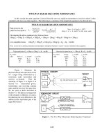
Three kinds of formulas
The definition:
Invented for a new concept
Q
C =
Q
V
{defines what capacitance is}
{does not require verification}
The law:
Summarizes a relationship that exists in nature
fK
Q
1
Q
2
{ifidb i t}
The
derivation
:
Obtained by manipulating other
f
=
K
d
2
{
ver
ifi
e
d
b
y exper
i
men
t}
The
derivation
:
Obtained
by
manipulating
other
formulas using mathematics
Q=CV
Q
=
CV
An
ideal voltage source
maintains a constant
An
ideal
voltage
source
maintains
a
constant
output voltage, regardless of the value of R
L
.
R
V
10 V lt
R
L
10 V
V
R
L
=
10
V
o
lt
s
The ideal model can be called
the first approximation.
A real voltage source has
a series resistance
a
series
resistance
.
R
L
10 V
R
S
V
R
L
< 10 Volts
L
10
V
R
L
This model is called the
th d i ti
th
e secon
d
approx
i
ma
ti
on.
When R
L
is equal to or greater than 100 times R
S
,areal
When
R
L
is
equal
to
or
greater
than
100
times
R
S
,
a
real
voltage source is stiff and the first approximation can be used.
An
ideal current source
maintains a constant
An
ideal
current
source
maintains
a
constant
output current, regardless of the value of R
L
.
R
I
1A
R
L
1 A
I
R
L
=
1
A
mpere
The ideal model can be called
the first approximation.
A real current source has
a shunt resistance
a
shunt
resistance
.
R
I
1A
R
R
L
1 A
I
R
L
<
1
A
mpere
R
S
This model is called the
th d i ti
th
e secon
d
approx
i
ma
ti
on.
When R
S
is equal to or greater than 100 times R
L
,areal
When
R
S
is
equal
to
or
greater
than
100
times
R
L
,
a
real
current source is stiff and the first approximation can be used.
Thevenin’s theorem can be used to replace any
linear circuit with an equivalent voltage source
linear
circuit
with
an
equivalent
voltage
source
called V
TH
and an equivalent resistance called R
TH
.
6
k
Ω
4
k
Ω
3
k
Ω
R
L
72 V
V
TH
R
TH
TH
TH
Remove the load.
Calculate or measure V
across the open terminals
Remove the source.
Calculate or measure R
TH
.
Calculate
or
measure
V
TH
across
the
open
terminals
.
Remove
the
source.
Calculate
or
measure
R
TH
.
When working with actual circuits,
please remember this
g
uideline:
The input impedance of
a voltmeter should be at least 100 times
greater than the Thevenin resistance to
avoid loading error.
DMMs are usually not a problem since they
DMMs
are
usually
not
a
problem
since
they
typically have an impedance of 10 MΩ.
6k
Ω
6
k
Ω
4
k
Ω
3 kΩ
R
L
72 V
The original
circuit
circuit
6 kΩ (R
TH
)
R
The Thevenin
R
L
24 V (V
TH
)
equivalent circuit
Norton’s theorem can be used to replace any
linear circuit with an equivalent current source
linear
circuit
with
an
equivalent
current
source
called I
N
and an equivalent resistance called R
N
.
6
k
Ω
4
k
Ω
3
k
Ω
R
L
72 V
I
N
R
N
N
N
Short the load to find I
R
N
i
s
th
e
s
am
e
a
s
R
TH
.
Short
the
load
to
find
I
N
.
N
ses es
TH
.
6k
Ω
6
k
Ω
4
k
Ω
3 kΩ
R
L
72 V
The original
circuit
circuit
The Norton
R
4A(I
)
equivalent circuit
6
k
Ω
(R
N
)
R
L
4
m
A
(I
N
)
6 kΩ (R
TH
)
ATh i
R
L
24 V (V
TH
)
A
Th
even
i
n
equivalent circuit
R
N
= R
TH
I
N
=
V
TH
R
TH
The Norton
dual
6 kΩ (R
N
)
R
L
4 mA (I
N
)
Troubleshooting
• A solder bridge between two lines
effectivel
y
shorts them to
g
ether.
yg
• A cold solder joint is effectively an open
circuit
circuit
.
• An intermittent trouble is one that
appears and disappears (could be a cold
appears
and
disappears
(could
be
a
cold
solder joint or a loose connection).
An open device
• The current through it is zero.
•
The voltage across it is unknown
The
voltage
across
it
is
unknown
.
• V = zero x infinity {indeterminate}
A shorted device
• The voltage across it is zero.
•
The current through it is unknown
The
current
through
it
is
unknown
.
• I = 0/0 {indeterminate}
A troubleshooting example:
Do the two 10 Ω resistors form
a sti
ff
volta
g
e divider?
10 Ω
100 kΩ
10
Ω
12 V
100 k
Ω
10
Ω
12
V
100
k
Ω
Wh
y
?
y
A troubleshooting example:
What are the expected
volta
g
es in this circuit?
10 Ω
100
k
Ω
10 Ω
12 V 100 kΩ
A troubleshooting example:
What are some causes for
this volta
g
e bein
g
too hi
g
h?
10 Ω
100 kΩ
10
Ω
12 V
100 k
Ω
V
10
Ω
12
V
100
k
Ω
V
A troubleshooting example:
What are some causes for
this volta
g
e bein
g
too low?
10 Ω
100 kΩ
10
Ω
12 V
100 k
Ω
V
10
Ω
12
V
100
k
Ω
V