Tài liệu 2waymon pdf
Bạn đang xem bản rút gọn của tài liệu. Xem và tải ngay bản đầy đủ của tài liệu tại đây (75.89 KB, 7 trang )
PHYSICAL CONCEPT
" , ONE-WAY SPACE LOSS
1
RECEIVER
TRANSMITTER
GAIN OF RCS
GAIN OF RCS
TRANSMITTER
RECEIVER
TRANSMITTER TO TARGET
TARGET TO RECEIVER
EQUIVALENT CIRCUIT
TARGET
P
G
G
t
t
P
G
r
r
P
t
G
t
G
r
P
r
F
G
F
" , ONE-WAY SPACE LOSS
1
" , ONE-WAY SPACE LOSS
1
P
r
'
P
t
G
t
G
r
8
2
F
(4B)
3
R
4
' P
t
G
t
G
r
Fc
2
(4B)
3
f
2
R
4
(
Note: 8'c/f and F ' RCS
(keep 8 or c, F, and R in the same units
4-4.1
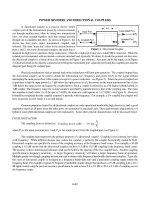
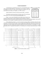
Figure 1. The Two-Way Monostatic Radar Equation Visualized
TWO-WAY RADAR EQUATION (MONOSTATIC)
In this section the radar equation is derived from the one-way equation (transmitter to receiver) which is then
extended to the two-way radar equation. The following is a summary of the important equations to be derived here:
TWO-WAY RADAR EQUATION (MONOSTATIC)
Peak power at the
radar receiver input is:
On reducing the above equation to log form we have:
10log P = 10log P + 10log G + 10log G + 10log F - 20log f - 40log R - 30log 4B + 20log c
r t t r
or in simplified terms: 10log P = 10log P + 10log G + 10log G + G - 2" (in dB)
r t t r F 1
Note: Losses due to antenna polarization and atmospheric absorption (Sections 3-2 and 5-1) are not included in these equations.
Target gain factor, G = 10log F + 20log f + K (in dB) One-way free space loss, " = 20log (f R) + K (in dB)
F 1 2 1 1 1
K Values
2
(dB) RCS (F) f in MHz f in GHz (dB) (units) K = K =
1 1
(units) K = K = NM 37.8 97.8
2 2
m -38.54 21.46 Km 32.45 92.45
2
ft -48.86 11.14 m -27.55 32.45
2
K Values Range f in MHz f in GHz
1 1 1
1 1
yd -28.33 31.67
ft -37.87 22.13
Figure 1 illustrates the
physical concept and equivalent circuit
for a target being illuminated by a
monostatic radar (transmitter and
receiver co-located). Note the
similarity of Figure 1 to Figure 3 in
Section 4-3. Transmitted power,
transmitting and receiving antenna
gains, and the one-way free space loss
are the same as those described in
Section 4-3. The physical arrangement
of the elements is different, of course,
but otherwise the only difference is the
addition of the equivalent gain of the
target RCS factor.
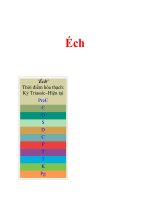
TWO WAY SIGNAL STRENGTH (S)
S decreases by 12 dB
when the distance doubles
S increases by 12 dB
when the distance is half
S
12 dB
(1/16 pwr)
12 dB
(16x pwr)
2R
R
R
0.5 R
S
Received Signal
at Target
'
P
t
G
t
G
r
8
2
(4BR)
2
Antenna Gain,G '
4BA
e
8
2
G
r
'
4BF
8
2
Reflected Signal
from target
'
P
t
G
t
8
2
4BF
(4BR)
2
8
2
Reflected Signal Received Back
at Input to Radar Receiver
'
P
t
G
t
8
2
4BF
(4BR)
2
8
2
x
G
r
8
2
(4BR)
2
P
r
'
P
t
G
t
G
r
8
2
F
(4B)
3
R
4
' P
t
G
t
G
r
Fc
2
(4B)
3
f
2
R
4
(
S (or P
r
) ' (P
t
G
t
G
r
) @
8
2
(4BR)
2
@
4BF
8
2
@
8
2
(4BR)
2
10log[S (or P
r
)] ' 10logP
t
% 10logG
t
% 10logG
r
% 20log
8
4BR
% 10log
4BF
8
2
% 20log
8
4BR
4-4.2
From Section 4-3, One-Way Radar Equation / RF Propagation, the power in the receiver is:
[1]
From equation [3] in Section 4-3: [2]
Similar to a receiving antenna, a radar target also intercepts a portion of the power, but reflects (reradiates) it in
the direction of the radar. The amount of power reflected toward the radar is determined by the Radar Cross Section (RCS)
of the target. RCS is a characteristic of the target that represents its size as seen by the radar and has the dimensions of
area (F) as shown in Section 4-11. RCS area is not the same as physical area. But, for a radar target, the power reflected
in the radar's direction is equivalent to re-radiation of the power captured by an antenna of area F (the RCS). Therefore,
the effective capture area (A ) of the receiving antenna is replaced by the RCS (F).
e
[3] so we now have: [4]
The equation for the power reflected in the radar's direction is the same as equation [1] except that P G , which
t t
was the original transmitted power, is replaced with the reflected signal power from the target, from equation [4]. This
gives:
[5]
If like terms are cancelled, the two-way radar equation
results. The peak power at the radar receiver input is:
[6]
* Note: 8=c/f and F = RCS. Keep 8 or c, F, and R in the same
units.
On reducing equation [6] to log form we have:
10log P = 10log P + 10log G + 10log G + 10log F - 20log f - 40log R - 30log 4B + 20log c [7]
r t t r
Target Gain Factor
If Equation [5] terms are rearranged instead of cancelled, a recognizable form results:
[8]
In log form:
[9]
where: K
2
' 10log
4B
c
2
@
Frequency and RCS
conversions as required
(Hz to MHz or GHz)
2
(meters to feet)
2
"
1
' 20log
4BfR
c
(
' 20log f
1
R % K
1
where K
1
' 20log
4B
c
@(Conversion units if not in m/sec, m, and Hz)
G
F
' 10log
4BF
8
2
' 10log
4BFf
2
c
2
' 10log F % 20log f
1
% K
2
(in dB)
G
F
' 10log F % 20log f
1
% 10log 4B @
sec
3x10
8
m
2
@m
2
@
1x10
6
sec
2
G
F
' 10log F % 20log f
1
& 38.54 (in dB)
4-4.3
One-way free space loss, " = 20log (f R) + K (in dB)
1 1 1
K Values Range f in MHz f in GHz
1 1 1
(dB) (units) K = K =
1 1
NM 37.8 97.8
Km 32.45 92.45
m -27.55 32.45
yd -28.33 31.67
ft -37.87 22.13
Target gain factor, G = 10log F + 20log f + K (in dB)
F 1 2
K Values
2
(dB) RCS (F) f in MHz f in GHz
1 1
(units) K = K =
2 2
m -38.54 21.46
2
ft -48.86 11.14
2
The fourth and sixth terms can each be recognized as -", where " is the one-way free space loss factor defined in
Section 4-3. The fifth term containing RCS (F) is the only new factor, and it is the "Target Gain Factor".
In simplified terms the equation becomes:
10log [S (or P )] = 10log P + 10log G + 10log G + G - 2" (in dB) [10]
r t t r F 1
Where " and G are as follows:
1 F
From Section 4-3, equation [11], the space loss in dB is given by:
[11]
* Keep c and R in the same units. The table of
values for K is again presented here for completeness. The
1
constant, K , in the table includes a range and frequency
1
unit conversion factor.
While it's understood that RCS is the antenna
aperture area equivalent to an isotropically radiated target
return signal, the target gain factor represents a gain, as
shown in the equivalent circuit of Figure 1. The Target
Gain Factor expressed in dB is G as shown in equation [12].
F
[12]
The "Target Gain Factor" (G ) is a composite of RCS, frequency, and dimension conversion factors and is called
F
by various names: "Gain of RCS", "Equivalent Gain of RCS", "Gain of Target Cross Section", and in dB form "Gain-sub-
Sigma".
If frequency is given in MHz and RCS (F) is in m , the formula for G is:
2
F
[13]
or: [14]
For this example, the constant K is -38.54 dB.
2
This value of K plus K for other area units and frequency
2 2
multiplier values are summarized in the adjoining table.
P
T
ERP
Radar
Receiver
Space Loss
SIGNAL POSITION IN SPACE
P
R
Approaching Target
*If power is actually measured in region A or B, it is stated
in either power density (mW/cm ) or field intensity (V/m)
2
A*
Space Loss
Returning From Target
B*
10 log P + 10 log G
t
t
- " - "
+ G
F
+ 10 log G 10 log P
r
r
Note: Not to scale
4-4.4
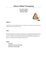
Figure 2. Visualization of Two-Way Radar Equation
In the two-way radar equation, the one-way free space loss factor (" ) is used twice, once for the radar transmitter
1
to target path and once for the target to radar receiver path. The radar illustrated in Figure 1 is monostatic so the two path
losses are the same and the values of the two " 's are the same.
1
If the transmission loss in Figure 1 from P to G equals the loss from G to P , and G = G , then equation [10]
t t r r r t
can be written as:
10log [S or P ] = 10log P + 20log G - 2" + G (in dB) [15]
r t tr 1 F
The space loss factor (" ) and the target gain factor (G ) include all the necessary unit conversions so that they can
1 F
be used directly with the most common units. Because the factors are given in dB form, they are more convenient to use
and allow calculation without a calculator when the factors are read from a chart or nomograph.
Most radars are monostatic. That is, the radar transmitting and receiving antennas are literally the same antenna.
There are some radars that are considered "monostatic" but have separate transmitting and receiving antennas that are co-
located. In that case, equation [10] could require two different antenna gain factors as originally derived:
10log [S or P ] = 10log P + 10log G + 10log G - 2" + G (in dB) [16]
r t t r 1 F
Note: To avoid having to include additional terms for these calculations, always combine any transmission line loss with
antenna gain.
Figure 2 is the visualization of the path losses occurring with the two-way radar equation. Note: to avoid having to include
additional terms, always combine any transmission line loss with antenna gain. Losses due to antenna polarization and
atmospheric absorption also need to be included.
P
t
G
t
G
r
8
2
F
(4B)
3
S
min
1
4
or
P
t
G
t
G
r
c
2
F]
(4B)
3
f
2
S
min
1
4
or
P
t
G
t
A
e
F
(4B)
2
S
min
1
4
10
MdB
40
S
min
' (S/N)
min
(NF)kT
0
B
P
t
G
t
G
r
8
2
F
(4B)
3
(S/N)
min
(NF)kT
0
B
1
4
or
P
t
G
t
G
r
c
2
F
(4B)
3
f
2
(S/N)
min
(NF)kT
o
B
1
4
or
P
t
G
t
A
e
F
(4B)
2
(S/N)
min
(NF)kT
o
B
1
4
4-4.5
One-way free space loss, " = 20log (f R) + K (in dB)
1 1 1
K Values Range f in MHz f in GHz
1 1 1
(dB) (units) K = K =
1 1
NM 37.8 97.8
Km 32.45 92.45
m -27.55 32.45
yd -28.33 31.67
ft -37.87 22.13
RADAR RANGE EQUATION (Two-Way Equation)
The Radar Equation is often called the "Radar Range Equation". The Radar Range Equation is simply the Radar
Equation rewritten to solve for maximum Range. The maximum radar range (R ) is the distance beyond which the target
max
can no longer be detected and correctly processed. It occurs when the received echo signal just equals S .
min
The Radar Range Equation is then: R – [17]
max
The first equation, of the three above, is given in Log form by:
40log R – 10log P + 10log G + 10log G + 10log F - 10log S - 20log f - 30log 4B + 20log c [18]
max t t r min
As shown previously, Since K = 20log [(4B/c) times conversion units if not in m/sec, m, and Hz], we have:
1
10log R – ¼ [10log P + 10log G + 10log G + 10log F - 10log S - 20log f - K - 10.99 dB] [19]
max t t r min 1 1
If you want to convert back from dB, then R –
max
Where M dB is the resulting number within the brackets of
equation 19.
From Section 5-2, Receiver Sensitivity / Noise, S is related to the noise factors by: [20]
min
The Radar Range Equation for a tracking radar (target continuously in the antenna beam) becomes:
R – [21]
max
P in equations [17], [19], and [21] is the peak power of a CW or pulse signal. For pulse signals these equations
t
assume the radar pulse is square. If not, there is less power since P is actually the average power within the pulse width
t
of the radar signal. Equations [17] and [19] relate the maximum detection range to S , the minimum signal which can
min
be detected and processed (the receiver sensitivity). The bandwidth (B) in equations [20] and [21] is directly related to S .
min
B is approximately equal to 1/PW. Thus a wider pulse width means a narrower receiver bandwidth which lowers S ,
min
assuming no integration.
One cannot arbitrarily change the receiver bandwidth, since it has to match the transmitted signal. The "widest
pulse width" occurs when the signal approaches a CW signal (see Section 2-11). A CW signal requires a very narrow
bandwidth (approximately 100 Hz). Therefore, receiver noise is very low and good sensitivity results (see Section 5-2).
If the radar pulse is narrow, the receiver filter bandwidth must be increased for a match (see Section 5-2), i.e. a 1 µs pulse
requires a bandwidth of approximately 1 MHz. This increases receiver noise and decreases sensitivity.
If the radar transmitter can increase its PRF (decreasing PRI) and its receiver performs integration over time, an
increase in PRF can permit the receiver to "pull" coherent signals out of the noise thus reducing S/N thereby increasing
min