Tài liệu Malvino-EP-03- Lý thuyết Diode pptx
Bạn đang xem bản rút gọn của tài liệu. Xem và tải ngay bản đầy đủ của tài liệu tại đây (193.16 KB, 15 trang )
Chương 3
Chương
3
Lý thuyết diode
Lý
thuyết
diode
Từ Vựng (1)
Từ
Vựng
(1)
•
anode
anode
• bulk resistance = điện trở khối
th d
•ca
th
o
d
e
• diode
• ideal diode = diode lý tưởng
•
knee voltage
=
điệnápgối
knee
voltage
điện
áp
gối
• linear device = dụng cụ tuyến tính
ldli đờ tải
•
l
oa
d
li
ne =
đ
ư
ờ
ng
tải
Từ Vựng (2)
Từ
Vựng
(2)
•
maximum forward current = dòng thuận
maximum
forward
current
=
dòng
thuận
cực đại
•
nonlinear device
=
dụng cụ phi tuyến
nonlinear
device
dụng
cụ
phi
tuyến
• Ohmic resistance = điện trở Ohm
ti đị h ứ ô ất
• power ra
ti
ng =
đị
n
h
m
ứ
c c
ô
ng su
ất
• up-down analysis = phân tích tăng-giảm
Nội dung chương 3
Nội
dung
chương
3
3-1 Các ý tưởng cơ bản
3-2 Diode lý tưởng
3-3 Xấp xỉ bậc 2
3-4 Xấp xỉ bậc 3
3-5 Trounleshooting
3-6 Phân tích mạch tăng-giảm
3-7 Đọc bản
g
dữ liệu
g
3-8 Cách tính điện trở khối
3-9 Điện trở DC của diode
3-10 Đườn
g
tải
g
3-11 Diode dán bề mặt
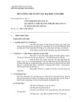
Properties of DiodesProperties of Diodes
Figure 1.10 Figure 1.10 –– The Diode Transconductance CurveThe Diode Transconductance Curve
22
•• VV
DD
= Bias Voltage= Bias Voltage
•• II
DD
= Current through = Current through
II
DD
(mA)(mA)
Diode. IDiode. I
DD
is Negative is Negative
for Reverse Bias and for Reverse Bias and
Positive for Forward Positive for Forward
BiBi
II
Bi
as
Bi
as
•• II
SS
= Saturation = Saturation
CurrentCurrent
VV
BRBR
II
SS
•• VV
BRBR
= Breakdown = Breakdown
VoltageVoltage
VV
DD
~V~V
φφ
••
VV
φφ
= Barrier Potential = Barrier Potential
VoltageVoltage
Kristin Ackerson, Virginia Tech EEKristin Ackerson, Virginia Tech EE
Spring 2002Spring 2002
(nA)(nA)
Properties of DiodesProperties of Diodes
The Shockley EquationThe Shockley Equation
•• The transconductance curve on the previous slide is characterized by The transconductance curve on the previous slide is characterized by
the following equation:the following equation:
II
DD
= I= I
SS
(e(e
VV
DD
//
ηη
VV
TT
––
1)1)
•• As described in the last slide, IAs described in the last slide, I
DD
is the current through the diode, Iis the current through the diode, I
SS
is is
th t ti t d Vth t ti t d V
ith lidbi i ltith lidbi i lt
th
e sa
t
ura
ti
on curren
t
an
d
Vth
e sa
t
ura
ti
on curren
t
an
d
V
DD
i
s
th
e app
li
e
d
bi
as
i
ng vo
lt
age.
i
s
th
e app
li
e
d
bi
as
i
ng vo
lt
age.
•• VV
TT
is the thermal equivalent voltage and is approximately 26 mV at room is the thermal equivalent voltage and is approximately 26 mV at room
temperature. The equation to find Vtemperature. The equation to find V
TT
at various temperatures is:at various temperatures is:
VV
TT
= = kTkT
k
=
138x10k
=
138x10
2323
J/K T
=
temperature in Kelvin q
=
16x10J/K T
=
temperature in Kelvin q
=
16x10
1919
CC
k
1
.
38
x
10k
1
.
38
x
10
J/K
T
temperature
in
Kelvin
q
1
.
6
x
10J/K
T
temperature
in
Kelvin
q
1
.
6
x
10
CC
•• ηη is the emission coefficient for the diode. It is determined by the way is the emission coefficient for the diode. It is determined by the way
the diode is constructed. It somewhat varies with diode current. For a the diode is constructed. It somewhat varies with diode current. For a
silicon diodesilicon diode
is aro nd 2 for lo c rrents and goes do n to abo t 1 atis aro nd 2 for lo c rrents and goes do n to abo t 1 at
Kristin Ackerson, Virginia Tech EEKristin Ackerson, Virginia Tech EE
Spring 2002Spring 2002
silicon
diode
silicon
diode
ηη
is
aro
u
nd
2
for
lo
w
c
u
rrents
and
goes
do
w
n
to
abo
u
t
1
at
is
aro
u
nd
2
for
lo
w
c
u
rrents
and
goes
do
w
n
to
abo
u
t
1
at
higher currentshigher currents
Diode Circuit ModelsDiode Circuit Models
The Ideal DiodeThe Ideal Diode
The diode is designed to allow current to flow inThe diode is designed to allow current to flow in
The
Ideal
Diode
The
Ideal
Diode
ModelModel
The
diode
is
designed
to
allow
current
to
flow
in
The
diode
is
designed
to
allow
current
to
flow
in
only one direction. The perfect diode would be a only one direction. The perfect diode would be a
perfect conductor in one direction (forward bias) perfect conductor in one direction (forward bias)
and a perfect insulator in the other directionand a perfect insulator in the other direction
and
a
perfect
insulator
in
the
other
direction
and
a
perfect
insulator
in
the
other
direction
(reverse bias). In many situations, using the ideal (reverse bias). In many situations, using the ideal
diode approximation is acceptable.diode approximation is acceptable.
Example: Assume the diode in the circuit below is ideal. Determine the Example: Assume the diode in the circuit below is ideal. Determine the
value of Ivalue of I
DD
if a) Vif a) V
AA
= 5 volts (forward bias) and b) V= 5 volts (forward bias) and b) V
AA
= = 5 volts (reverse 5 volts (reverse
bias)bias)
II
RR
S S
= 50 = 50 ΩΩ
a) With Va) With V
AA
> 0 the diode is in forward bias > 0 the diode is in forward bias
and is acting like a perfect conductor so:and is acting like a perfect conductor so:
II
=V=V
/R/R
=5V/50=5V/50
ΩΩ
= 100 mA= 100 mA
++
VV
AA
II
DD
II
DD
=
V=
V
AA
/R/R
SS
=
5
V
/
50
=
5
V
/
50
ΩΩ
=
100
mA=
100
mA
b) With Vb) With V
AA
< 0 the diode is in reverse bias < 0 the diode is in reverse bias
and is actin
g
like a perfect insulator, and is actin
g
like a perfect insulator,
Kristin Ackerson, Virginia Tech EEKristin Ackerson, Virginia Tech EE
Spring 2002Spring 2002
__
gg
therefore no current can flow and therefore no current can flow and II
DD
= 0.= 0.
Diode Circuit ModelsDiode Circuit Models
The Ideal Diode withThe Ideal Diode with
This model is more accurate than the simpleThis model is more accurate than the simple
The
Ideal
Diode
with
The
Ideal
Diode
with
Barrier PotentialBarrier Potential
This
model
is
more
accurate
than
the
simple
This
model
is
more
accurate
than
the
simple
ideal diode model because it includes the ideal diode model because it includes the
approximate barrier potential voltage. approximate barrier potential voltage.
Remember the barrier potential voltage is theRemember the barrier potential voltage is the
++
Remember
the
barrier
potential
voltage
is
the
Remember
the
barrier
potential
voltage
is
the
voltage at which appreciable current starts to voltage at which appreciable current starts to
flow.flow.
Example: To be more accurate than just using the ideal diode model Example: To be more accurate than just using the ideal diode model
VV
φφ
++
include the barrier potential. Assume Vinclude the barrier potential. Assume V
φφ
= 0.3 volts (typical for a = 0.3 volts (typical for a
germanium diode) Determine the value of Igermanium diode) Determine the value of I
DD
if Vif V
AA
= 5 volts (forward bias).= 5 volts (forward bias).
II
DD
RR
S S
= 50 = 50 ΩΩ
With VWith V
A A
> 0 the diode is in forward bias > 0 the diode is in forward bias
and is acting like a perfect conductor and is acting like a perfect conductor
so write a KVL equation to find Iso write a KVL equation to find I
::
++
__
VV
AA
II
DD
so
write
a
KVL
equation
to
find
Iso
write
a
KVL
equation
to
find
I
DD
::
0 = V0 = V
AA
––II
DD
RR
SS
VV
φφ
II
DD
= V= V
AA
VV
φφ
= 4.7 V = 4.7 V = 94 mA = 94 mA
VV
++
Kristin Ackerson, Virginia Tech EEKristin Ackerson, Virginia Tech EE
Spring 2002Spring 2002
φφ
RR
SS
50 50
ΩΩ
VV
φφ
Diode Circuit ModelsDiode Circuit Models
The Ideal DiodeThe Ideal Diode
This model is the most accurate of the three It includes aThis model is the most accurate of the three It includes a
The
Ideal
Diode
The
Ideal
Diode
with Barrier with Barrier
Potential and Potential and
Li F dLi F d
This
model
is
the
most
accurate
of
the
three
.
It
includes
a
This
model
is
the
most
accurate
of
the
three
.
It
includes
a
linear forward resistance that is calculated from the slope of linear forward resistance that is calculated from the slope of
the linear portion of the transconductance curve. However, the linear portion of the transconductance curve. However,
this is usually not necessary since the Rthis is usually not necessary since the R
FF
(forward (forward
Li
near
F
orwar
d
Li
near
F
orwar
d
Resistance Resistance
resistance) value is pretty constant. For lowresistance) value is pretty constant. For low power power
germanium and silicon diodes the Rgermanium and silicon diodes the R
FF
value is usually in the value is usually in the
2 to 5 ohms range, while higher power diodes have a R2 to 5 ohms range, while higher power diodes have a R
FF
value closer to 1 ohm.value closer to 1 ohm.
value
closer
to
1
ohm.value
closer
to
1
ohm.
Linear Portion of Linear Portion of
transconductancetransconductance
II
DD
++
VV
φφ
RR
FF
transconductance
transconductance
curvecurve
II
VV
II
DD
RR
FF
= = VV
DD
II
DD
VV
DD
VV
DD
Kristin Ackerson, Virginia Tech EEKristin Ackerson, Virginia Tech EE
Spring 2002Spring 2002
Diode Circuit ModelsDiode Circuit Models
The Ideal DiodeThe Ideal Diode
ElA thdidilElA thdidil
di ddi d
The
Ideal
Diode
The
Ideal
Diode
with Barrier with Barrier
Potential and Potential and
Li F dLi F d
E
xamp
l
e:
A
ssume
th
e
di
o
d
e
i
s a
l
ow
E
xamp
l
e:
A
ssume
th
e
di
o
d
e
i
s a
l
ow power
di
o
d
e power
di
o
d
e
with a forward resistance value of 5 ohms. The with a forward resistance value of 5 ohms. The
barrier potential voltage is still: Vbarrier potential voltage is still: V
φφ
= 0.3 volts (typical = 0.3 volts (typical
for a germanium diode) Determine the value of Ifor a germanium diode) Determine the value of I
ifif
Li
near
F
orwar
d
Li
near
F
orwar
d
Resistance Resistance
for
a
germanium
diode)
Determine
the
value
of
Ifor
a
germanium
diode)
Determine
the
value
of
I
DD
if
if
VV
AA
= 5 volts.= 5 volts.
RR
S S
= 50 = 50 ΩΩ
Once again, write a KVL equationOnce again, write a KVL equation
++
VV
AA
II
DD
++
Once
again,
write
a
KVL
equation
Once
again,
write
a
KVL
equation
for the circuit:for the circuit:
0 = V0 = V
AA
––II
DD
RR
SS
VV
φφ
II
DD
RR
FF
__
VV
φφ
++
RR
FF
II
DD
= V= V
AA
VV
φφ
= 5 = 5 –– 0.3 = 85.5 mA0.3 = 85.5 mA
RR
SS
+ R+ R
FF
50 + 550 + 5
Kristin Ackerson, Virginia Tech EEKristin Ackerson, Virginia Tech EE
Spring 2002Spring 2002
RR
FF
Diode Circuit ModelsDiode Circuit Models
Values of ID for the Three Different Diode Circuit ModelsValues of ID for the Three Different Diode Circuit Models
Values
of
ID
for
the
Three
Different
Diode
Circuit
ModelsValues
of
ID
for
the
Three
Different
Diode
Circuit
Models
Ideal Diode
Model with
Ideal Diode
Model with
Ideal Diode
Model
Model
with
Barrier
Potential
V
olta
g
e
Barrier
Potential and
Linear Forward
Resistance
g
Resistance
I
D
100 mA 94 mA 85.5 mA
These are the values found in the examples on previous These are the values found in the examples on previous
slides where the applied voltage was 5 volts the barrierslides where the applied voltage was 5 volts the barrier
Kristin Ackerson, Virginia Tech EEKristin Ackerson, Virginia Tech EE
Spring 2002Spring 2002
slides
where
the
applied
voltage
was
5
volts
,
the
barrier
slides
where
the
applied
voltage
was
5
volts
,
the
barrier
potential was 0.3 volts and the linear forward resistance potential was 0.3 volts and the linear forward resistance
value was assumed to be 5 ohms.value was assumed to be 5 ohms.
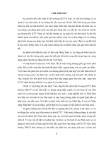
The Q PointThe Q Point
The operating point or Q point of the diode is the quiescent or noThe operating point or Q point of the diode is the quiescent or no
The
operating
point
or
Q
point
of
the
diode
is
the
quiescent
or
noThe
operating
point
or
Q
point
of
the
diode
is
the
quiescent
or
no
signal condition. The Q point is obtained graphically and is really only signal condition. The Q point is obtained graphically and is really only
needed when the applied voltage is very close to the diode’s barrier needed when the applied voltage is very close to the diode’s barrier
potential voltage. The examplepotential voltage. The example
33
below that is continued on the nextbelow that is continued on the next
potential
voltage.
The
example
potential
voltage.
The
example
below
that
is
continued
on
the
next
below
that
is
continued
on
the
next
slide, shows how the Q point is determined using the slide, shows how the Q point is determined using the
transconductance curve and the load line.transconductance curve and the load line.
Fir
st
t
h
e
l
oad
lin
e
i
s
f
ou
n
d
by
subst
i
tut
in
g
in Fir
st
t
h
e
l
oad
lin
e
i
s
f
ou
n
d
by
subst
i
tut
in
g
in
RR
S S
= 1000 = 1000 ΩΩ
st t e oad e s ou d by subst tut gst t e oad e s ou d by subst tut g
different values of Vdifferent values of V
φφ
into the equation for Iinto the equation for I
DD
using using
the ideal diode with barrier potential model for the the ideal diode with barrier potential model for the
diode. With Rdiode. With R
SS
at 1000 ohms the value of Rat 1000 ohms the value of R
FF
wouldn’t have much impact on the resultswouldn’t have much impact on the results
++
VV
AA
=6V=6V
II
DD
++
wouldn’t
have
much
impact
on
the
results
.
wouldn’t
have
much
impact
on
the
results
.
II
DD
= V= V
AA
––V V
φφ
RR
SS
__
=
6V=
6V
VV
φφ
++
Using V Using V
φφ
values of 0 volts and 1.4 volts we obtain values of 0 volts and 1.4 volts we obtain
II
DD
values of 6 mA and 4.6 mA respectively. Next values of 6 mA and 4.6 mA respectively. Next
we will draw the line connecting these two points we will draw the line connecting these two points
th h ith th t d tth h ith th t d t
Kristin Ackerson, Virginia Tech EEKristin Ackerson, Virginia Tech EE
Spring 2002Spring 2002
on
th
e grap
h
w
ith
th
e
t
ranscon
d
uc
t
ance curve. on
th
e grap
h
w
ith
th
e
t
ranscon
d
uc
t
ance curve.
This line is the load line.This line is the load line.
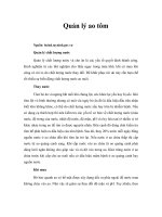
The Q PointThe Q Point
II
DD
(mA)(mA)
The The
transconductancetransconductance
II
DD
(mA)(mA)
1212
transconductance
transconductance
curve below is for a curve below is for a
Silicon diode. The Silicon diode. The
Q
p
oint in this Q
p
oint in this
88
1010
pp
example is located example is located
at 0.7 V and 5.3 mA.at 0.7 V and 5.3 mA.
66
88
5353
Q Point: Q Point: The intersection of the The intersection of the
load line and the load line and the
transconductance curve.transconductance curve.
44
4.64.6
5
.
35
.
3
VV
DD
(Volts)(Volts)
22
VV
DD
(Volts)(Volts)
0.20.2 0.40.4 0.60.6 0.80.8 1.01.0 1.21.2 1.41.4
Kristin Ackerson, Virginia Tech EEKristin Ackerson, Virginia Tech EE
Spring 2002Spring 2002
0.70.7
Dynamic ResistanceDynamic Resistance
The d
y
namic resistance of the diode is mathematicall
y
determined The d
y
namic resistance of the diode is mathematicall
y
determined
yyyy
as the inverse of the slope of the transconductance curve. as the inverse of the slope of the transconductance curve.
Therefore, the equation for dynamic resistance is:Therefore, the equation for dynamic resistance is:
rr
==
ηη
VV
rr
FF
=
=
ηη
VV
TT
II
DD
The dynamic resistance is used in determining the voltage dropThe dynamic resistance is used in determining the voltage drop
The
dynamic
resistance
is
used
in
determining
the
voltage
drop
The
dynamic
resistance
is
used
in
determining
the
voltage
drop
across the diode in the situation where a voltage source is across the diode in the situation where a voltage source is
supplying a sinusoidal signal with a dc offset.supplying a sinusoidal signal with a dc offset.
The ac component of the diode voltage is found using the The ac component of the diode voltage is found using the
following equation:following equation:
vv
FF
=
v
=
v
acac
rr
FF
vv
FF
v
v
ac
ac
rr
FF
rr
FF
+ R+ R
SS
The volta
g
e drop throu
g
h the diode is a combination of the ac and The volta
g
e drop throu
g
h the diode is a combination of the ac and
Kristin Ackerson, Virginia Tech EEKristin Ackerson, Virginia Tech EE
Spring 2002Spring 2002
gggg
dc components and is equal to:dc components and is equal to:
VV
DD
= V= V
φφ
+ v+ v
FF
Dynamic ResistanceDynamic Resistance
ElEl
E
xamp
l
e:
E
xamp
l
e: Use the same circuit used for the Q point example but change Use the same circuit used for the Q point example but change
the voltage source so it is an ac source with a dc offset. The source the voltage source so it is an ac source with a dc offset. The source
voltage is now, vvoltage is now, v
inin
= 6 + sin(wt) Volts. It is a silicon diode so the barrier = 6 + sin(wt) Volts. It is a silicon diode so the barrier
t ti l lt i till 0 7 ltt ti l lt i till 0 7 lt
po
t
en
ti
a
l
vo
lt
age
i
s s
till
0
.
7
vo
lt
s.po
t
en
ti
a
l
vo
lt
age
i
s s
till
0
.
7
vo
lt
s.
RR
S S
= 1000 = 1000 ΩΩ
The DC component of the circuit is the The DC component of the circuit is the
same as the previous example and same as the previous example and
th f Ith f I
6V6V
07V07V
53 A53 A
++
vv
II
DD
th
ere
f
ore
Ith
ere
f
ore
I
DD
= =
6V
6V
––
0
.
7
V0
.
7
V
=
5
.
3
m
A
=
5
.
3
m
A
1000 1000 ΩΩ
rr
FF
= = ηηVV
T T
= = 1 * 26 mV1 * 26 mV = 4.9 = 4.9 ΩΩ
vv
inin
VV
φφ
++
II
D D
5.3 mA5.3 mA
ηη = 1 is a good approximation if the dc = 1 is a good approximation if the dc
current is greater than 1 mA as it is in thiscurrent is greater than 1 mA as it is in this
current
is
greater
than
1
mA
as
it
is
in
this
current
is
greater
than
1
mA
as
it
is
in
this
example.example.
vv
FF
= v= v
acac
rr
FF
= sin(wt) V 4.9 = sin(wt) V 4.9 ΩΩ = 4.88 sin(wt) mV= 4.88 sin(wt) mV
rr
+R+R
4949
ΩΩ
+ 1000+ 1000
ΩΩ
Kristin Ackerson, Virginia Tech EEKristin Ackerson, Virginia Tech EE
Spring 2002Spring 2002
rr
FF
+
R+
R
SS
4
.
9
4
.
9
ΩΩ
+
1000
+
1000
ΩΩ
Therefore, VTherefore, V
DD
= 700 + 4.9 sin (wt) mV (the voltage drop across the = 700 + 4.9 sin (wt) mV (the voltage drop across the
diode)diode)