Tài liệu Programming the Be Operating System-Chapter 5: Drawing ppt
Bạn đang xem bản rút gọn của tài liệu. Xem và tải ngay bản đầy đủ của tài liệu tại đây (544.78 KB, 43 trang )
134
Chapter 5
In this chapter:
• Colors
• Patterns
• The Drawing Pen
• Shapes
5
Drawing 5.
When a Be application draws, it always draws in a view. That’s why the chapter
that deals with views precedes this chapter. In Chapter 4, Windows, Views, and
Messages, you saw that a BView-derived class overrides its inherited hook mem-
ber function Draw() so that it can define exactly what view objects should draw
in when they get updated. The example projects in this chapter contain classes
and member functions that remain unchanged, or changed very little, from previ-
ous example projects. What will be different is the content of the Draw() function.
The code that demonstrates the concepts of each drawing topic can usually be
added to the Draw() routine.
In Be programming, the colors and patterns that fill a shape aren’t defined explic-
itly for that shape. Instead, traits of the graphics environment of the view that
receives the drawing are first altered. In other words, many drawing characteris-
tics, such as color and font, are defined at the view level, so all subsequent draw-
ing can use the view settings. In this chapter, you’ll see how to define a color,
then set a view to draw in that color. You’ll see how the same is done for pat-
terns—whether using Be-defined patterns or your own application-defined ones.
After you learn how to manipulate the graphic characteristics of a view, it’s on to
the drawing of specific shapes. The point (represented by BPoint objects) is used
on its own, to define the end points of a line, and to define the vertices of more
sophisticated shapes (such as triangles or polygons). The rectangle (represented by
BRect objects) is used on its own and as the basis of more sophisticated shapes.
These shapes include round rectangles, ellipses, and regions. Round rectangles
and ellipses are closely related to BRect objects, and aren’t defined by their own
classes. Polygons and regions are more sophisticated shapes that make use of
points and rectangles, but are represented by their own class types (BPolygon and
BRegion). In this chapter, you’ll see how to outline and fill each of these different
Colors 135
shapes. Finally, I show how to combine any type and number of these various
shapes into a picture represented by a BPicture object.
Colors
The BeOS is capable of defining colors using any of a number of color spaces.A
color space is a scheme, or system, for representing colors as numbers. There are
several color space Be-defined constants, each containing a number that reflects
the number of bits used to represent a single color in a single pixel. For instance,
the B_COLOR_8_BIT color space devotes 8 bits to defining the color of a single
pixel. The more memory devoted to defining the color of a single pixel, the more
possible colors a pixel can display.
B_GRAY1
Each pixel in a drawing is either black (bit is on, or 1) or white (bit is off, or
0).
B_GRAY8
Each pixel in a drawing can be one of 256 shades of gray—from black (bit is
set to a value of 255) to white (bit is set to a value of 0).
B_CMAP8
Each pixel in a drawing can be one of 256 colors. A pixel value in the range
of 0 to 255 is used as an index into a color map. This system color map is
identical for all applications. That means that when two programs use the
same value to color a pixel, the same color will be displayed.
B_RGB15
Each pixel in a drawing is created from three separate color components: red,
green, and blue. Five out of a total of sixteen bits are devoted to defining each
color component. The sixteenth bit is ignored.
B_RGB32
Like the B_RGB15 color space, each pixel in a drawing is created from three
separate color components: red, green, and blue. In B_RGB32 space, how-
ever, eight bits are devoted to defining each color component. The remaining
eight bits are ignored.
B_RGBA32
Like the B_RGB32 color space, each pixel in a drawing is created from three
separate color components: red, green, and blue. Like B_RGB, eight bits are
used to define each of the three color components. In B_RGBA32 space, how-
ever, the remaining eight bits aren’t ignored—they’re devoted to defining an
alpha byte, which is used to specify a transparency level for a color.
136 Chapter 5: Drawing
RGB Color System
As listed above, the BeOS supports a number of color spaces. The RGB color
space is popular because it provides over sixteen million unique colors (the num-
ber of combinations using values in the range of 0 to 255 for each of the three
color components), and because it is a color system with which many program-
mers and end users are familiar with (it’s common to several operating systems).
The BeOS defines rgb_color as a struct with four fields:
typedef struct {
uint8 red;
uint8 green;
uint8 blue;
uint8 alpha;
} rgb_color
A variable of type rgb_color can be initialized at the time of declaration. The
order of the supplied values corresponds to the ordering of the struct defini-
tion. The following declares an rgb_color variable named redColor and assigns
the red and alpha fields a value of 255 and the other two fields a value of 0:
rgb_color redColor = {255, 0, 0, 255};
To add a hint of blue to the color defined by redColor, the third value could be
changed from 0 to, say, 50. Because the alpha component of a color isn’t sup-
ported at the time of this writing, the last value should be 255. Once supported, an
alpha value of 255 will represent a color that is completely opaque; an object of
that color will completely cover anything underneath it. An alpha field value of 0
will result in a color that is completely transparent—an effect you probably don’t
want. An rgb_color variable can be set to represent a new color at any time by
specifying new values for some or all of the three color components. Here an
rgb_color variable named blueColor is first declared, then assigned values:
rgb_color blueColor;
blueColor.red = 0;
blueColor.green = 0;
blueColor.blue = 255;
blueColor.alpha = 255;
While choosing values for the red, green, and blue components of a
color is easy if you want a primary color, the process isn’t com-
pletely intuitive for other colors. Quickly now, what values should
you use to generate chartreuse? To experiment with colors and their
RGB components, run the ColorControl program that’s discussed a
little later in this chapter. By the way, to create the pale, yellowish
green color that’s chartreuse, try values of about 200, 230, and 100
for the red, green, and blue components, respectively.
Colors 137
High and Low Colors
Like all graphics objects, an rgb_color variable doesn’t display any color in a
window on its own—it only sets up a color for later use. A view always keeps
track of two colors, dubbed the high and low colors. When you draw in the view,
you specify whether the current high color, the current low color, or a mix of the
two colors should be used.
Views and default colors
When a new view comes into existence, it sets a number of drawing characteris-
tics to default values. Included among these are:
• A high color of black
• A low color of white
• A background color of white
Additionally, when a BView drawing function is invoked, by default it uses the
view’s high color for the drawing. Together, these facts tell you that unless you
explicitly specify otherwise, drawing will be in black on a white background.
Setting the high and low colors
The BView member functions SetHighColor() and SetLowColor() alter the
current high and low colors of a view. Pass SetHighColor() an rgb_color and
that color becomes the new high color—and remains as such until the next call to
SetHighColor(). The SetLowColor() routine works the same way. This next
snippet sets a view’s high color to red and its low color to blue:
rgb_color redColor = {255, 0, 0, 255};
rgb_color blueColor = {0, 0, 255, 255};
SetHighColor(redColor);
SetLowColor(blueColor);
Drawing with the high and low colors
Passing an rgb_color structure to SetHighColor() or SetLowColor() estab-
lishes that color as the one to be used by a view when drawing. Now let’s see
how the high color is used to draw in color:
rgb_color redColor = {255, 0, 0, 255};
BRect aRect(10, 10, 110, 110);
SetHighColor(redColor);
FillRect(aRect, B_SOLID_HIGH);
138 Chapter 5: Drawing
The previous snippet declares redColor to be a variable of type rgb_color and
defines that variable to represent red. The snippet also declares a BRect variable
named aRect, and sets that variable to represent a rectangle with a width and
height of 100 pixels. The call to SetHighColor() sets the high color to red.
Finally, a call to the BView member function FillRect() fills the rectangle aRect
with the current high color (as specified by the Be-defined constant B_SOLID_
HIGH)—the color red.
Shape-drawing routines such as FillRect() are described in detail later in this
chapter. For now, a brief introduction will suffice. A shape is typically drawn by
first creating a shape object to define the shape, then invoking a BView member
function to draw it. That’s what the previous snippet does: it creates a rectangle
shape based on a BRect object, then calls the BView member function
FillRect() to draw the rectangle.
One of the parameters to a BView shape-drawing routine is a pattern. As you’ll see
ahead in the “Patterns” section of this chapter, a pattern is an 8-pixel-by-8-pixel
template that defines some combination of the current high color and low color.
This small template can be repeatedly “stamped” into an area of any size to fill that
area with the pattern. Patterns are everywhere these days: desktop backgrounds,
web page backgrounds, and so on. You can create your own patterns, or use one
of the three Be-defined patterns. Each of the Be-defined patterns is represented by
a constant:
• B_SOLID_HIGH is a solid fill of the current high color.
• B_SOLID_LOW is a solid fill of the current low color.
• B_MIXED_COLORS is a checkerboard pattern of alternating current high color
and low color pixels (providing a dithered effect—what looks like a single
color blended from the two colors).
A view’s default high color is black. So before a view calls SetHighColor(), the
use of B_SOLID_HIGH results in a solid black pattern being used. The above snip-
pet invokes SetHighColor() to set the current high color to red, so subsequent
uses of B_SOLID_HIGH for this one view result in a solid red pattern being used.
Determining the current high and low colors
You can find out the current high or low color for a view at any time by invoking
the BView member functions HighColor() or LowColor(). Each routine returns
a value of type rgb_color. This snippet demonstrates the calls:
rgb_color currentHighColor;
rgb_color currentLowColor;
currentHighColor = HighColor();
currentLowColor = LowColor();
Colors 139
The default high color is black, so if you invoke HighColor() before using
SetHighColor(),anrgb_color with red, green, and blue field values of 0 will
be returned to the program. The default low color is white, so a call to
LowColor() before a call to SetLowColor() will result in the return of an rgb_
color with red, green, and blue field values of 255. Because the alpha field of
the high and low colors is ignored at the time of this writing, the alpha field will
be 255 in both cases.
RGB, low, and high color example project
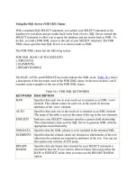
The RGBColor project is used to build a program that displays a window like the
one shown in Figure 5-1. Given the nature of this topic, you can well imagine that
the window isn’t just as it appears in this figure. Instead a shade of each being a
shade of gray, the three rectangles in the window are, from left to right, red, blue,
and a red-blue checkerboard. Because of the high resolution typical of today’s
monitors, the contents of the rightmost rectangle dither to a solid purple rather
than appearing to the eye as alternating red and blue pixels.
Chapter 4 included the TwoViewClasses project—a project that introduced a new
view class named MyDrawView. That class definition was almost identical to the
original MyHelloView. This chapter’s RGBColor project and all remaining projects
in this chapter display a single window that holds a single MyDrawView view, and
no MyHelloView.SotheMyHelloView.cpp file is omitted from these projects, and
the data member meant to keep track of a MyHelloView in the MyHelloWindow
class (reproduced below) is also omitted:
class MyHelloWindow : public BWindow {
public:
MyHelloWindow(BRect frame);
virtual bool QuitRequested();
private:
MyDrawView *fMyDrawView;
};
Figure 5-1. The window that results from running the RGBColor program
140 Chapter 5: Drawing
Creating a new MyHelloWindow object now entails creating just a single
MyDrawView view that fills the window, then attaching the view to the window:
MyHelloWindow::MyHelloWindow(BRect frame)
: BWindow(frame, "My Hello", B_TITLED_WINDOW, B_NOT_RESIZABLE)
{
frame.OffsetTo(B_ORIGIN);
fMyDrawView = new MyDrawView(frame, "MyDrawView");
AddChild(fMyDrawView);
Show();
}
Drawing in a view takes place automatically when the system calls the view’s
Draw() routine. That function is the code I play with in order to try out drawing
ideas. Here’s how the RGBColor project implements the MyDrawView version of
Draw():
void MyDrawView::Draw(BRect)
{
BRect aRect;
rgb_color redColor = {255, 0, 0, 255};
rgb_color blueColor;
blueColor.red = 0;
blueColor.green = 0;
blueColor.blue = 255;
blueColor.alpha = 255;
SetHighColor(redColor);
SetLowColor(blueColor);
aRect.Set(10, 10, 110, 110);
FillRect(aRect, B_SOLID_HIGH);
aRect.Set(120, 10, 220, 110);
FillRect(aRect, B_SOLID_LOW);
aRect.Set(230, 10, 330, 110);
FillRect(aRect, B_MIXED_COLORS);
}
The previous routine demonstrates two methods of assigning an rgb_color vari-
able a color value. After that, the SetHighColor() and SetLowColor() func-
tions set the MyDrawView high color and low color to red and blue, respectively.
Then in turn each of the three rectangles is set up, then filled.
The View Color (Background)
To color a shape, the program often refers to the B_SOLID_HIGH constant. As you
just saw in the previous example project, the B_SOLID_LOW and B_MIXED_COLORS
Colors 141
constants can also be used to include the view’s current low color in the drawing.
By now it should be apparent that neither the high nor low color implicitly has
anything to do with a view’s background color.
Setting a view’s background color
By default, a new view has a background color of white. This background color
can be set to any RGB color by invoking the BView member function
SetViewColor(). Here a view’s background color is being set to purple:
rgb_color purpleColor = {255, 0, 255, 255};
SetViewColor(purpleColor);
Calling SetViewColor() changes the background color of a view without affect-
ing either the high color or the low color. Consider a view with a current high
color of blue, a current low color of yellow, and a background color set to pur-
ple. Calling a BView fill routine with a pattern argument of B_SOLID_HIGH draws
a blue shape. An argument of B_SOLID_LOW draws a yellow shape. Finally, an
argument of B_MIXED_COLORS draws a green shape. All shapes are drawn against
the view’s purple background.
View color example project
The ViewColor program displays a window that looks identical to that displayed
by the RGBColor example, except for one feature. Both programs display a win-
dow with a red, blue, and purple rectangle in it, but the ViewColor window back-
ground is pink rather than white. This trick is performed by adding just a few lines
of code to the AttachedToWindow() routine defined in the MyDrawView.cpp file
in the RGBColor project. Here an rgb_color variable is set up to define the color
pink, and that variable is used as the argument to a call to SetViewColor().
Here’s the new version of the MyDrawView member function
AttachedToWindow():
void MyDrawView::AttachedToWindow()
{
SetFont(be_bold_font);
SetFontSize(24);
rgb_color pinkColor = {255, 160, 220, 255};
SetViewColor(pinkColor);
}
Color Control View
The RGB components of any given color won’t be known by a program’s user.
There are exceptions, of course—graphics artists involved in electronic media or
142 Chapter 5: Drawing
electronic publications may have a working knowledge of how RGB values corre-
spond to colors. Those exceptions aside, if your program allows users to select
their own colors, your program should provide a very user-friendly means for
them to accomplish this task. The BColorControl class does just that.
Color levels and the BColorControl object
The BColorControl class is derived from the BControl class, which itself is
derived from the BView class. So a BColorControl object is a type of view. Your
program creates a BColorControl object in order to allow a user to select an
RGB color without the user knowing anything about the RGB color system or RGB
values.
What the BColorControl object displays to the user depends on the number of
colors the user’s monitor is currently displaying. The user can set that parameter
by choosing Screen from the preferences menu in the Deskbar. Coincidentally, the
Screen preferences window (which has been revamped and turned into the Back-
ground preferences application) itself holds a BColorControl object. So you can
see how the monitor’s color depth is set and take a look at a BColorControl
object by selecting the Screen preferences or by simply looking at Figure 5-2.
The Screen preferences window holds a number of objects representing BView-
derived classes. Among them is a pop-up menu titled Colors. In Figure 5-2, you
see that I have my monitor set to devote 8 bits of graphics memory to each pixel,
so my monitor can display up to 256 colors. The Screen preferences window lets
me choose one of the 256 system colors to be used as my desktop color. This is
done by clicking on one of the 256 small colored squares. This matrix, or block of
squares, is a BColorControl object.
Figure 5-2. The Screen preferences program set to display 8-bit color
Colors 143
Choosing 32-Bits/Pixel from the Colors pop-up menu in the Screen preferences
window sets a monitor to display any of millions of colors. As shown in
Figure 5-3, doing so also changes the look of the BColorControl object. Now a
color is selected by clicking on the red, green, and blue ramps, or bands, of color
along the bottom of the Screen preferences window. Unbeknownst to the user,
doing this sets up an RGB color. The Screen preferences program combines the
user’s three color choices and uses the resulting RGB value as the desktop color.
Creating a BColorControl object
The Screen preferences window serves as a good example of how a
BColorControl object can help the user. To use the class in your own program,
declare a BColorControl object and the variables that will be used as parame-
ters to the BColorControl constructor. Then create the new object using new and
the BColorControl constructor:
BColorControl *aColorControl;
BPoint leftTop(20.0, 50.0);
color_control_layout matrix = B_CELLS_16x16;
long cellSide = 16;
aColorControl = new BColorControl(leftTop, matrix, cellSide, "ColorControl");
AddChild(aColorControl);
The first BColorControl constructor parameter, leftTop, indicates where the top
left corner of the color control should appear. The color control will be placed in
a view (by calling the AddChild() function of the host view, as shown above), so
you should set BPoint’s coordinates relative to the view’s borders.
The second parameter, matrix, is of the Be-defined datatype color_control_
layout. When the user has the monitor set to 8 bits per pixel, the 256 system col-
ors are displayed in a matrix. This parameter specifies how these squares should
Figure 5-3. The Screen preferences program set to display 32-bit color
144 Chapter 5: Drawing
be arranged. Use one of five Be-defined constants here: B_CELLS_4x64, B_
CELLS_8x32, B_CELLS_16x16, B_CELLS_32x8,orB_CELLS_64x4. The two num-
bers in each constant name represent the number of columns and rows, respec-
tively, that the colored squares are placed in. For example, B_CELLS_32x8 dis-
plays the 256 colors in eight rows with 32 colored squares in each row.
The third BColorControl constructor parameter, cellSide, determines the pixel
size of each colored square in the matrix. A value of 10, for instance, results in 256
squares that are each 10 pixels by 10 pixels in size.
The fourth parameter provides a name for the BColorControl object. Like any
view, a BColorControl object has a name that can be used to find the view. The
name can be supplied using a string (as shown in the previous snippet) or by
passing in a constant variable that was defined as a const char * (as in const
char *name = "ColorControl";).
Note that the overall size of the BColorControl object isn’t directly specified in
the constructor. The size is calculated by the constructor, and depends on the val-
ues supplied in the second and third parameters. The matrix parameter specifies
the shape of the block of colors, while the cellSide value indirectly determines
the overall size. A matrix with 8 rows of cells that are each 10 pixels high will
have a height of 80 pixels, for instance.
I’ve discussed the BColorControl constructor parameters as if they will be used
with 8-bit pixels. For the values used in the previous example, the resulting color
control looks like the one displayed in the window in Figure 5-4. If the user
instead has the monitor set to 32 bits for each pixel, the same arguments are used
in the display of four bands, three of which the user clicks on in order to create a
single color. The top gray band represents the alpha, or color transparency level,
component. As of this writing, the alpha component is unimplemented, but it
should be implemented by the time you read this. Instead of creating a matrix of
color squares, the arguments are now used to determine the shape and overall
size the four bands occupy. Figure 5-5 shows the color control that results from
executing the previous snippet when the monitor is set to 32 bits per pixel.
The user can set the monitor to the desired bits-per-pixel level, so
your program can’t count on being used for a matrix or bands. In
Figure 5-5, you see that the color bands are very broad—that’s the
result of specifying a 16-by-16 matrix (B_CELLS_16x16). To display
longer, narrower color bands, choose a different Be-defined con-
stant for the BColorControl constructor matrix argument (such as
B_CELLS_64x4). Regardless of the values you choose for the
matrix and cellSize parameters, test the resulting color control
under both monitor settings to verify that the displayed control fits
well in the window that displays it.
Colors 145
Using a color control
When a window displays a color control, the user selects a color by clicking on its
cell (if the user’s monitor is set to 8 bits per pixel) or by clicking on a color inten-
sity in each of the three color component bands (if the user’s monitor is set to 32
bits per pixel). In either case, the BColorControl object always keeps track of
the currently selected color. Your program can obtain this color at any time via a
call to the BColorControl member function ValueAsColor(). Obviously
enough, a call to this routine returns the value of the color control object in the
form of an RGB color. In this next snippet, the user’s current color choice is
returned and stored in an rgb_color variable named userColorChoice:
rgb_color userColorChoice;
userColorChoice = aColorControl->ValueAsColor();
What your program does with the returned color is application-specific. Just bear
in mind that this value can be used the same way any rgb_color is used. You
know about the SetHighColor() routine that sets a view’s high color, and you’ve
seen how to fill a rectangle with the current high color by calling the BView mem-
ber function FillRect(), so an example that carries on with the previous snip-
pet’s userColorChoice RGB color will be easily understandable:
BRect aRect(40.0, 50.0, 400.0, 55.0);
SetHighColor(userColorChoice);
FillRect(aRect, B_SOLID_HIGH);
The previous snippet creates a rectangle in the shape of a long horizontal bar, sets
the high color to whatever color the user has the color control currently set at,
then fills the rectangle with that color.
ColorControl example project
If you set your monitor to use 8 bits per pixel (using the Screen preferences util-
ity), running this chapter’s ColorControl example program results in a window like
the one shown in Figure 5-4. If you instead have your monitor set to use 32 bits
per pixel, running the same program displays a window like that shown in
Figure 5-5.
Regardless of your monitor’s pixel setting, the ColorControl program displays three
text boxes to the right of the color matrix or color bands. These text boxes are dis-
played automatically by the BColorControl object, and the area they occupy
constitutes a part of the total area occupied by the control. If you click on a color
cell or a color band, the numbers in these boxes will change to reflect the appro-
priate RGB values for the color you’ve selected. If you click in a text box (or use
the Tab key to move to a text box) and type in a value between 0 and 255, the
146 Chapter 5: Drawing
Figure 5-4. The ColorControl program’s window that results from running at 8-bit color
Figure 5-5. The ColorControl program’s window that results from running at 32-bit color
Colors 147
color display will update itself to display the color that best matches the value
you’ve entered. These actions are all automatic, and require no coding effort on
your part. The reason this handy feature works is that the BControl class over-
rides the BView class member function KeyDown(), and in turn the
BColorControl class overrides the BControl version of KeyDown(). The
BColorControl version of the routine sees to it that the text box values reflect
the displayed color.
If you move the cursor out of the color control area (keep in mind that this area
includes the text boxes), then click the mouse button, a long, narrow bar is drawn
along the bottom of the window—as shown in Figures 5-4 and 5-5. The color of
this bar will match whatever color you have currently selected in the color con-
trol. The selection of this color and the drawing of the bar are handled by the
MyDrawView version of the MouseDown() routine. Besides overriding the Bview
hook function MouseDown(), this project’s version of the MyDrawView class adds a
BColorControl data member. The color control data member will be used to
keep track of the control. Here’s how the ColorControl project declares the
MyDrawView class:
class MyDrawView : public BView {
public:
MyDrawView(BRect frame, char *name);
virtual void AttachedToWindow();
virtual void Draw(BRect updateRect);
virtual void MouseDown(BPoint point);
private:
BColorControl *fColorControl;
};
The MyHelloApplication class and MyHelloWindow class are almost identical to
versions found in previous examples. The MyHelloApplication constructor
defines the size of a window and creates a single MyHelloWindow, and the
MyHelloWindow defines a single MyDrawView whose size is the same as the win-
dow it resides in.
The MyDrawView constructor, which in other projects has been empty, sets up and
creates a color control. The control object is added to the newly created
MyDrawView object as a child:
MyDrawView::MyDrawView(BRect rect, char *name)
: BView(rect, name, B_FOLLOW_ALL, B_WILL_DRAW)
{
BPoint leftTop(20.0, 50.0);
color_control_layout matrix = B_CELLS_16x16;
long cellSide = 16;
fColorControl = new BColorControl(leftTop, matrix, cellSide,
148 Chapter 5: Drawing
"ColorControl");
AddChild(fColorControl);
}
In the MyDrawView constructor, you see that the control will have its top left cor-
ner start 20 pixels from the left and 50 pixels from the top of the MyDrawView
view that the control appears in. Starting down 50 pixels from the top of the view
leaves room for the two lines of instructional text that are displayed in the win-
dow (refer back to Figure 5-4 or 5-5). Those lines are drawn each time the system
has to update the view they appear in:
void MyDrawView::Draw(BRect)
{
MovePenTo(BPoint(20.0, 20.0));
DrawString("Choose a color below, then move the cursor");
MovePenTo(BPoint(20.0, 35.0));
DrawString("outside of the color control and click the mouse button");
}
When the user clicks in the MyDrawView view, the MouseDown() routine that the
MyDrawView class overrides is automatically invoked:
void MyDrawView::MouseDown(BPoint point)
{
BRect aRect(20.0, 330.0, 350.0, 340.0);
rgb_color userColorChoice;
userColorChoice = fColorControl->ValueAsColor();
SetHighColor(userColorChoice);
FillRect(aRect, B_SOLID_HIGH);
}
MouseDown() creates the long, thin rectangle that appears along the bottom of the
view when the user clicks the mouse button. Before this function draws the rect-
angle with a call to FillRect(),aValueAsColor() call obtains the color cur-
rently selected in the view’s color control. A call to SetHighColor() makes the
user-selected color the one used in function calls that include B_SOLID_HIGH as a
parameter.
Improving the ColorControl example project
For brevity, the ColorControl example sets the high color and fills in the colored
rectangle in the MouseDown() routine. Typically, drawing takes place only in a
view’s Draw() function. One way to accomplish that would be to move the code
currently in MouseDown() to Draw():
void MyDrawView::Draw(BRect)
{
BRect aRect(20.0, 330.0, 350.0, 340.0);
Colors 149
rgb_color userColorChoice;
MovePenTo(BPoint(20.0, 20.0));
DrawString("Choose a color below, then move the cursor");
MovePenTo(BPoint(20.0, 35.0));
DrawString("outside of the color control and click the mouse button");
userColorChoice = fColorControl->ValueAsColor();
SetHighColor(userColorChoice);
FillRect(aRect, B_SOLID_HIGH);
}
The body of MouseDown() could then consist of a single line of code: a call to the
BView function Invalidate(). Then, when the user clicks the mouse in the
MyDrawView view, MouseDown() makes the system aware of the fact that the view
needs updating, and the system invokes Draw():
void MyDrawView::MouseDown(BPoint point)
{
Invalidate();
}
One further improvement to the ColorControl example program would be to pre-
serve the current state of the view before changing its high color. As implemented
(here and in the previous section), the text the program draws is drawn in black
the first time the Draw() function executes. Subsequent calls will update any pre-
viously obscured text (as in the case when an overlapping window is moved off
the ColorControl program’s window) in whatever color was selected by the user.
That is, the program’s call to SetHighColor() affects not only the long, narrow
color rectangle at the bottom of the program’s window, but also text drawn with
calls to DrawString(). To remedy this, preserve the state of the high color by
invoking the BView function HighColor() to get the current high color before
changing it. After calling SetHighColor() and FillRect(), use the rgb_color
value returned by HighColor() to reset the high color to its state prior to the use
of the user-selected color. Here’s how Draw() now looks:
void MyDrawView::Draw(BRect)
{
BRect aRect(20.0, 330.0, 350.0, 340.0);
rgb_color userColorChoice;
rgb_color origHighColor;
MovePenTo(BPoint(20.0, 20.0));
DrawString("Choose a color below, then move the cursor");
MovePenTo(BPoint(20.0, 35.0));
DrawString("outside of the color control and click the mouse button");
origHighColor = HighColor();
userColorChoice = fColorControl->ValueAsColor();
SetHighColor(userColorChoice);
150 Chapter 5: Drawing
FillRect(aRect, B_SOLID_HIGH);
SetHighColor(origHighColor);
}
Patterns
A pattern is an 8-pixel-by-8-pixel area. Each of the 64 pixels in this area has the
color of either the current high or current low color. A pattern can be one solid
color (by designating that all pixels in the pattern be only the current high color or
only the current low color), or it can be any arrangement of the two colors, as in a
checkerboard, stripes, and so forth. Regardless of the arrangement of the pixels
that make up the pattern, it can be used to fill an area of any size. And regardless
of the size or shape of an area, once a pattern is defined it can be easily “poured”
into this area to give the entire area the look of the pattern.
Be-Defined Patterns
You’ve already encountered three patterns—the Be-defined constants B_SOLID_
HIGH, B_SOLID_LOW, B_MIXED_COLORS each specify a specific arrangement of col-
ors in an 8-pixel-by-8-pixel area. Here the B_MIXED_COLORS pattern is used to fill
a rectangle with a checkerboard pattern made up of alternating current high and
current low colors:
BRect aRect(20.0, 20.0, 300.0, 300.0);
FillRect(aRect, B_MIXED_COLORS);
The BView class defines a number of stroke and fill member functions. Each
stroke function (such as StrokeRect() and StrokePolygon()) outlines a shape
using a specified pattern. Patterns have the greatest effect on the look of a shape
outline when the outline has a thickness greater than one pixel (setting the thick-
ness at which lines are drawn is covered ahead in the “The Drawing Pen” sec-
tion). Each fill function (such as FillRect() and FillPolygon()) fills a shape
using a specified pattern. This may not be entirely obvious when looking at some
source code snippets because these drawing routines make the pattern parameter
optional. When the pattern parameter is skipped, the function uses the B_SOLID_
HIGH pattern by default. So both of the following calls to FillRect() produce a
rectangle filled with a solid pattern in the current high color:
BRect rect1(100.0, 100.0, 150.0, 150.0);
BRect rect2(150.0, 150.0, 200.0, 200.0);
FillRect(rect1, B_SOLID_HIGH);
FillRect(rect2);
Patterns 151
Earlier in this chapter, the example project RGBColor demonstrated the use of the
B_SOLID_HIGH, B_SOLID_LOW, and B_MIXED_COLORS constants by using these
constants in the filling of three rectangles (see Figure 5-1). After setting the high
color to red and the low color to blue, the rectangle that was filled using the
B_MIXED_COLORS constant appeared to be purple. I say “appeared to be purple”
because, in fact, none of the pixels in the rectangle are purple. Instead, each is
either red or blue. Because the pixels alternate between these two colors, and
because pixel density is high on a typical monitor, the resulting rectangle appears
to the eye to be solid purple. Figure 5-6 illustrates this by showing the RGBColor
program’s window and the window of the pixel-viewing utility program Magnify.
The Magnify program (which is a Be-supplied application that was placed on your
machine during installation of the BeOS) shows an enlarged view of the pixels
surrounding the cursor. In Figure 5-6, the cursor is over a part of the purple rect-
angle in the RGBColor window, and the pixels are displayed in the Magnify win-
dow.
Application-Defined Patterns
The three Be-defined patterns come in handy, but they don’t exploit the real
power of patterns. Your project can define a pattern that carries out precisely your
idea of what a shape should be filled with.
Figure 5-6. Using the Magnify program to view the B_MIXED_COLORS pattern
152 Chapter 5: Drawing
Bit definition of a pattern
A pattern designates which of the 64 bits (8 rows of 8 bits) in an 8-pixel-by-8-pixel
area display the current high color and which display the current low color. Thus
the specific colors displayed by the pattern aren’t designated by the pattern.
Instead, a pattern definition marks each of its 64 bits as either a 1 to display the
high color or a 0 to display the low color. The colors themselves come from the
high and low colors at the time the pattern is used in drawing.
A pattern is specified by listing the hexadecimal values of the eight bits that make
up each row of the pattern. Consider the pattern shown in Figure 5-7. Here I show
the 8-by-8 grid for a pattern that produces a diagonal stripe. You can do the same
using a pencil and graph paper. Each cell represents one pixel, with a filled-in cell
considered on, or 1, and an untouched cell considered off, or 0. Since a pattern
defines only on and off, not color, this technique works fine regardless of the col-
ors to be used when drawing with the pattern.
The left side of Figure 5-7 shows the binary representation of each row in the pat-
tern, with a row chunked into groups of four bits. The right side of the figure
shows the corresponding hexadecimal values for each row. Looking at the top
row, from left to right, the pixels are on/on/off/off, or binary 1100. The second set
of four pixels in the top row has the same value. A binary value of 1100 is hexa-
decimal c, so the binary pair translates to the hexadecimal pair cc. The hexadeci-
mal values for each remaining row are determined in the same manner. If you’re
proficient at working with hexadecimal values, you can skip the intermediate
binary step and write the hexadecimal value for each row by simply looking at the
pixels in groups of four.
Row by row, the hexadecimal values for the pattern in Figure 5-7 are: cc, 66, 33,
99, cc, 66, 33, 99. Using the convention of preceding a hexadecimal value with 0x,
the pattern specification becomes: 0xcc, 0x66, 0x33, 0x99, 0xcc, 0x66, 0x33, 0x99.
Figure 5-7. The binary and hexadecimal representations of a pattern
Patterns 153
The pattern datatype
Using the previous method to define a pattern isn’t just an exercise in your knowl-
edge of hexadecimal numbers, of course! Instead, you’ll use a pattern’s eight hexa-
decimal pairs in assigning a pattern variable. Here’s how Be defines the
pattern datatype:
typedef struct {
uchar data[8];
} pattern;
Each of the eight elements in the pattern array is one byte in size, so each can
hold a single unsigned value in the range of 0 to 255. Each of the hexadecimal
pairs in each of the eight rows in a pattern falls into this range (0x00 = 0, 0xff =
255). To create a pattern variable, determine the hexadecimal pairs for the pat-
tern (as shown above) and assign the variable those values. Here I’m doing that
for the pattern I designed back in Figure 5-7:
pattern stripePattern = {0xcc, 0x66, 0x33, 0x99, 0xcc, 0x66, 0x33, 0x99};
This is also how Be defines its three built-in patterns. The B_SOLID_HIGH pattern
is one that has all its bits set to 1, or on; the B_SOLID_LOW pattern has all its bits
set to 0, or off; and the B_MIXED_COLORS pattern has its bits set to alternate
between 1 and 0:
const pattern B_SOLID_HIGH = {0xff, 0xff, 0xff, 0xff, 0xff, 0xff, 0xff, 0xff}
const pattern B_SOLID_LOW = {0x00, 0x00, 0x00, 0x00, 0x00, 0x00, 0x00, 0x00}
const pattern B_MIXED_COLORS = {0xaa, 0x55, 0xaa, 0x55, 0xaa, 0x55, 0xaa, 0x55}
Using a pattern variable
Once initialized, a variable of type pattern is used just as one of the Be-defined
pattern constants—pass the variable as an argument to any routine that requires a
pattern as a parameter. The following snippet defines a pattern variable and two
rectangle variables. The code then fills one rectangle with a solid color and the
other with diagonal stripes:
pattern stripePattern = {0xcc, 0x66, 0x33, 0x99, 0xcc, 0x66, 0x33, 0x99};
BRect solidRect(10.0, 10.0, 110.0, 110.0);
BRect stripedRect(200.0, 10.0, 210.0, 110.0);
FillRect(solidRect, B_SOLID_HIGH);
FillRect(stripedRect, stripePattern);
Because the previous snippet doesn’t include any code that hints at the current
state of the high and low colors, you can’t infer what colors will be in the result-
ing rectangles—you know only that one will have a solid fill while the other will
have diagonal stripes running through it.
154 Chapter 5: Drawing
Pattern example project
The Pattern project builds a program that displays a window with a single rectan-
gle drawn in it. The rectangle is filled with the diagonal stripe pattern that was
introduced on the preceding pages. Figure 5-8 shows the Pattern program’s win-
dow. Also shown is the Magnify program’s window as it displays an enlarged view
of some of the pixels in the Pattern program’s filled rectangle.
As is the case for many of this chapter’s remaining examples, the Pattern project
was created by starting with a recent project (such as the RGBColor project) and
altering the code in just one of the routines—the Draw() member function of the
MyDrawView class. Here’s how the new version of that routine looks:
void MyDrawView::Draw(BRect)
{
BRect aRect;
pattern stripePattern = {0xcc, 0x66, 0x33, 0x99, 0xcc, 0x66, 0x33, 0x99};
aRect.Set(10.0, 10.0, 110.0, 110.0);
FillRect(aRect, stripePattern);
}
You can experiment with the Pattern project by adding color to the rectangle. Pre-
cede the call to FillRect() with a call to SetHighColor(), SetLowColor(),or
both. Changing the current high color will change the color of what are presently
Figure 5-8. Using the Magnify program to view the application-defined pattern
The Drawing Pen 155
the black stripes, while changing the current low color will change the color of
what are presently the white stripes.
The Drawing Pen
Whenever drawing takes place, the pen is at work. The pen is a way to summa-
rize and express two properties of a view’s drawing environment. When drawing
starts, it starts at some specific location in a view. When line drawing takes place,
the line has some specific thickness to it. These traits are stored in a view and can
be altered by invoking BView member functions. In keeping with the analogy of
drawing with a pen, the names of these routines include the word “pen.”
Pen Location
The location of the rectangle drawn by Fillrect() has been previously estab-
lished during the setting up of the rectangle:
BRect aRect(10.0, 10.0, 110.0, 110.0);
FillRect(aRect, B_SOLID_HIGH);
For the drawing of text and lines, this isn’t the case. Typically, you’ll move the pen
to the location where drawing is to start, then draw.
Moving the pen
When it’s said that the pen is moved, what’s actually taking place is that a call sets
the starting location for subsequent drawing. Moving the pen doesn’t have any vis-
ible effect—nothing gets drawn. To move the pen, invoke the view’s
MovePenTo() or MovePenBy() function.
The MovePenTo() function accepts either a single BPoint argument or a pair of
floating-point arguments. In either case, the result is that the arguments specify the
coordinate at which the next act of drawing starts. The first argument to
MovePenTo() is the horizontal coordinate to move to, while the second argument
is the vertical coordinate. The movement is relative to the view’s origin. Each of
the following four calls to MovePenTo() has the same result—drawing will be set
to start at pixel (30.0, 40.0) in the view’s system coordinate:
BPoint aPoint(30.0, 40.0);
float x = 30.0;
float y = 40.0;
MovePenTo(aPoint);
MovePenTo(BPoint(30.0, 40.0));
MovePenTo(30.0, 40.0);
MovePenTo(x, y);
156 Chapter 5: Drawing
Like MovePenTo(), the MovePenBy() function moves the starting location for
drawing. MovePenTo() moves the pen relative to the view’s origin. MovePenBy()
moves the pen relative to its current location in the view. Consider this snippet:
MovePenTo(30.0, 40.0);
MovePenBy(70.0, 10.0);
The call to MovePenTo() moves the pen to the location 30 pixels from the left of
the view and 40 pixels from the top of the view. That places the pen at the point
(30.0, 40.0). The call to MovePenBy() uses this current location as the reference
and moves the pen 70 pixels to the left and 10 pixels down. The result is that, rel-
ative to the view’s origin, the pen is at the point (100.0, 50.0).
Negative values for MovePenBy() move the pen “backwards” in the view. A nega-
tive horizontal argument moves the pen to the left, while a negative vertical argu-
ment moves the pen up. Because MovePenTo() specifies a particular coordinate
to end up at rather than a direction to move in, negative values shouldn't be
passed as the arguments of this routine.
MovePen example project
As shown in Figure 5-9, the MovePen project results in a program that displays a
window with three characters written to it. I’ve added coordinate information to
the figure—the arrows and values aren’t actually displayed in the window.
Where the characters “A,” “B,” and “C” get drawn in the window depends on calls
to the MovePenTo() and MovePenBy() functions. To get a good feel for working
with a view’s coordinate system, edit the arguments to the existing function calls in
the Draw() routine, or add additional calls to MovePenTo() and MovePenBy():
void MyDrawView::Draw(BRect)
{
Figure 5-9. The window that results from running the MovePen program
60.0
80.0
A
110.0
200.0
B
C
100.0
The Drawing Pen 157
MovePenTo(BPoint(80.0, 60.0));
DrawString("A");
MovePenTo(200.0, 110.0);
DrawString("B");
MovePenBy(100.0, 0.0);
DrawString("C");
}
Pen Size
The pen is used to draw shape outlines. Chapter 4 introduced the BView member
function StrokeRect(), which draws the outline of a rectangle. Here a 100-pixel-
by-100-pixel rectangle is framed in a view:
BRect aRect(10.0, 10.0, 110.0, 110.0);
StrokeRect(aRect);
As you’ll see later in this chapter, there are a number of BView StrokeXxx()
member functions, each of which outlines a particular shape. All of these func-
tions are affected by the current size of the pen.
Setting the pen size
By default, the pen can be thought of as having a tip that is the size of a single
pixel. Thus, drawing with the pen produces a line with a thickness of one pixel.
You can change the size or thickness of the pen at any time by invoking the
BView member function SetPenSize(). This routine accepts a single argument,
the new pixel thickness for the pen. In this next snippet, the same rectangle that
was outlined in the previous snippet is given a frame, or border, three pixels thick.
The lines you specify to be drawn are in the center of the pixels in a thick pen.
BRect aRect(10.0, 10.0, 110.0, 110.0);
SetPenSize(3.0);
StrokeRect(aRect);
Setting the pen size for a view affects all subsequent calls to StrokeXxx() func-
tions. After changing the pen size and invoking a StrokeXxx() function, you may
want to reset the pen size to a thickness of a single pixel:
SetPenSize(3.0);
StrokeRect(aRect);
SetPenSize(1.0);
Getting the pen size
The best process to use when altering the pen size is to obtain and save the cur-
rent pen size, change it, perform the desired drawing using the new pen size, then
158 Chapter 5: Drawing
restore the pen to the saved size. The BView member function PenSize() allows
you to do that. When invoked, PenSize() returns a float that holds the current
thickness of the pen. This next snippet provides an example of the use of
PenSize():
float savedPenSize;
savedPenSize = PenSize();
SetPenSize(3.0);
StrokeRect(aRect);
SetPenSize(savedPenSize);
PenSize example project
The PenSize project displays a window that holds six rectangles. As shown in
Figure 5-10, the thickness of the outline of each rectangle differs.
As is becoming a habit, the Draw() function of the MyDrawView class does the
example’s work. The function begins by defining and setting six rectangles. Each
rectangle has a width of 40 pixels and a height of 80 pixels. The outline thickness
of each rectangle differs due to the call to SetPenSize() that precedes each call
to StrokeRect():
void MyDrawView::Draw(BRect)
{
BRect rect1(20.0, 20.0, 60.0, 100.0);
BRect rect2(80.0, 20.0, 120.0, 100.0);
BRect rect3(140.0, 20.0, 180.0, 100.0);
BRect rect5(200.0, 20.0, 240.0, 100.0);
BRect rect8(260.0, 20.0, 300.0, 100.0);
BRect rect12(320.0, 20.0, 360.0, 100.0);
SetPenSize(1.0);
StrokeRect(rect1);
SetPenSize(2.0);
StrokeRect(rect2);
SetPenSize(3.0);
StrokeRect(rect3);
Figure 5-10. The window that results from running the PenSize program


![Tài liệu Beginning the Linux Command Line [Apress 2009] ppt](https://media.store123doc.com/images/document/13/ce/kn/medium_zPbk2szWHh.jpg)