Tài liệu CDMA truy cập và chuyển mạch P3 pptx
Bạn đang xem bản rút gọn của tài liệu. Xem và tải ngay bản đầy đủ của tài liệu tại đây (413.86 KB, 25 trang )
3
Switched CDMA Networks
3.1 Overview
Code Division Multiple Access (CDMA) has been widely accepted and used for
wireless access in terrestrial and satellite applications. These applications often require
switching of the CDMA traffic channels in order to establish connectivity between
end users. In existing terrestrial wireless networks, while CDMA is used for access,
connectivity and routing is achieved via the Public Switched Telephone Network
(PSTN). It is often desirable, however, that access and switching is performed within
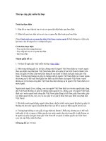
the same network in many applications. An example of such an application is the
Satellite Switched CDMA (SS/CDMA) system presented in [1]. The SS/CDMA
network is comprised of a multibeam satellite and a large population of ground users,
as illustrated in Figure 3.1-A. Ground users within each beam access the satellite
by CDMA. The satellite is equipped with an on-board switch for routing inter- or
intra-beam calls. The SS/CDMA network is described in detail in Section 3.2. Similar
satellite systems based on TDMA, called Satellite Switched TDMA (SS/TDMA), are
presented elsewhere [2], [3] and [4].
As in the satellite example, CDMA switching may also be used in terrestrial
applications. These applications include wireless and cable networks that have CDMA
as their access method. An example of such a network, called Base-station Switched
CDMA (BS/CDMA), is illustrated in Figure 3.1-B. The BS/CDMA is comprised
of a CDMA exchange node connected to a number of Radio Distribution Points
(RDPs) via distribution lines which carry the CDMA signal. The exchange node
in this case provides the switching capability for establishing connectivity between
the wireless users. This wireless network may be used for fixed or mobile services.
Similar systems based on TDMA have also been proposed (see [5] and [6]). Reference
[5] presents a wireless TDMA switching system which provides connectivity between
mobile users in a community of interest, while reference [6] presents another TDMA
switching system for fixed service wireless metropolitan area networks. In addition
to wireless applications, CDMA has been proposed for standardization in coax-cable
networks for providing upstream voice, data and video services (see reference [7]). In
this case, a switching CDMA device at the exchange node will provide an efficient
mechanism for routing CDMA channels between cable users. Such an application is
called Cable-Switched CDMA (CS/CDMA), and is illustrated in Figure 3.1-C. The
above applications, both satellite and terrestrial, are refered to by the term switched
CDMA (SW/CDMA) networks.
CDMA: Access and Switching: For Terrestrial and Satellite Networks
Diakoumis Gerakoulis, Evaggelos Geraniotis
Copyright © 2001 John Wiley & Sons Ltd
ISBNs: 0-471-49184-5 (Hardback); 0-470-84169-9 (Electronic)
58 CDMA: ACCESS AND SWITCHING
CDMA
Exchange
Node
RDP
RDP
RDP
RDP
RDP
RDP
SS/CDMA
A. The satellite switched CDMA (SS/CDMA)
B. The base station switched CDMA (BS/CDMA)
CDMA
Exchange
Node
H/EH/E
H/E
H/E
PSTN
Coax-cable
Network
C. The cable switched CDMA (CS/CDMA)
H/E:Head-End
PSTN: Public Switched
Telephone Network
RDP: Radio Distribution Point
n
Figure 3.1 Switched CDMA (SW/CDMA) networks.
SWITCHED CDMA NETWORKS 59
In this chapter we focus our attention on the satellite switched CDMA system. We
present the network architecture, the access method and switching mechanism, and
describe the design of its system units. We also examine the network operation and
control algorithm.
3.2 Satellite Switched CDMA (SS/CDMA)
The service needs for future geostationary satellite systems demand direct two-way
communication between end satellite users having Ultra Small Aperture Terminals
(USAT) (antenna dish 26
in diameter). The requirement for this type of service is
the capability of call routing on-board the satellite. That is, the satellite will operate
not only as a repeater, but also as a switching center in space. Such services, however,
can only become economically feasible if the satellite communication capacity and
throughput is sufficiently high while its service quality is comparable to the quality of
wireline service. For this reason the system has to provide higher spectral efficiency,
but also more efficient utilization of the available mass and power of the spacecraft.
Higher spectral efficiency is achieved by using multibeam satellite antennas which allow
resuse of the available spectrum. Also, the power needs of the transceiver units can be
reduced by introducing new access and modulation methods operating at a very low
signal-to-noise ratio in order to allow the use of USAT. Also, higher throughput can be
achieved with a demand assignment control mechanism, which allows the distribution
of system functionalities between the satellite and end users.
The system proposed to meet the above needs is the Satellite Switched Code Division
Multiple Access (SS/CDMA). The SS/CDMA resolves both the multiple access and
the satellite switching problems. The uplink access method is based on CDMA,
the downlink on Code Division Multiplexing (CDM) and the on-board switching on
compatible technology which is also code division (CDS). The system operates with
demand assignment control for both access and switching. That is, service bandwidth
and switch connections are assigned only upon a user request. The SS/CDMA can
achieve higher spectral efficiency by allowing frequency reuse, i.e. reuse of the available
spectrum in every beam of a multibeam satellite. In addition, it provides an efficient
switching mechanism by establishing a direct end-to-end route with minimal on-board
signal processing and no on-board buffering. The access and switching problems are
resolved in one step by the demand assignment control mechanism. This approach also
allows system optimization by using an assignment control algorithm to maximize
throughput and to integrate the traffic of circuit calls and data packets. A large
population of end users may then access the geostationary satellite which provides
the routing of calls and packets between them. The system may offer fixed services for
circuit switched calls (voice, data and video) and packet switched data.
A related method based on Time Division Multiple Access (TDMA), called Satellite
Switched TDMA (SS/TDMA), has been proposed in the past for packet switched
data services, [2], [3]. In SS/TDMA the access method is TDMA and the switching
is based on time multiplexing (TMS). A similar TDMA demand assignment system
is also used in the ACTS satellite for low burst rate traffic [4]. The TDMA approach,
however, requires frequency reuse of 1/4 or 1/7 (depending on the beamwidth), while
its switch implementation and algorithm control may be more complex for large switch
sizes.
60 CDMA: ACCESS AND SWITCHING
Uplink
Downlink
Gateway
PSTN
PSDN
ISL
ISL: Inter-Satellite Links
Figure 3.2 The Satellite Switched CDMA (SS/CDMA).
The SS/CDMA system has been developed for AT&T’s VoiceSpan satellite project
and Ka-band application filling (the VoiceSpan project has not been realized). In
the following section we present the system description, in Section 3.2.2 the satellite
switching mechanism, in Section 3.2.3 the description of transmitter and the receiver
units, and in Section 3.2.4 the network operation and control.
3.2.1 System Description
The Satellite Switched Code Division Multiple Access (SS/CDMA) is the underlying
communication system proposed for a network of satellites. This network is comprised
of the space segment containing a number of geostationary satellites and the ground
segment containing the Customer Premises Equipment (CPE) and gateway offices
to the Public Switched Telephone and Data Networks (PSTN and PSDN). The
geostationary satellites are equipped with multibeam antennas, on-board processing
and switching for providing fixed service communications. The network configuration
is shown in Figure 3.2.
Transmission Rates and Services
The main objective of the satellite network is to provide services with a direct
connection to each subscriber. The services offered are both circuit switched and packet
switched. The circuit switched services are for voice, video and data, while the packet
switched services are only for data. The transmission bit rates, the source bit rates and
the quality of each circuit switched service are shown in Table 3.1. The transmission
rate in each channel type includes a source rate, a subrate, framing bits, and a frame
quality indicator (CRC). The offered rates for voice services are: 16, 32, and 64 Kbps;
SWITCHED CDMA NETWORKS 61
Tab le 3.1 Transmission and source bit rates and the corresponding
services.
Channel Source Transmiss. Service Required
Type Rate(kb/s) Rate(kb/s) Offer BER
I 64 76.8 Voice/Data 10
−6
II 32 38.4 Voice/Data 10
−6
III 16 19.2 Voice/Data 10
−6
IV 144 153.6 ISDN(2B+D) 10
−6
V 384 460.8 Video 10
−8
VI 1544 2304 T1 10
−8
VII 2048 2304 E1 10
−8
while the offered rates for data are: 16, 64 and basic ISDN 144 kbps (2B+D). The
system also offers video services with rate of 384 Kbps and 4.608 Mbps, and T1 or
(E1) carriers with rates of 1544 (or 2048) Kbps. Each transmission rate is the result of
multiplexing the source data with the frame quality indicator, signaling data and/or
other information data. Each channel Type (I, II) corresponds to a required Bit Error
Rate (BER). The SS/CDMA system will also offer packet switched services for bursty
data.
Multiple Access
The SS/CDMA provides both multiple access and switching to the multibeam satellite.
The multiple access problem is resolved by space, frequency and code division. The
space division multiple access is achieved by multibeam antennas in order to reuse the
available spectrum in each beam. The frequency division multiple access is achieved
by segmenting the available spectrum into frequency bands, each having a convenient
size of 10 MHz (see Figure 3.3). The Code Division Multiple Access (CDMA) will
then provide access for each user within each frequency band and in each beam. The
CDMA will spread the user data over the bandwidth of 10 MHz.
The satellite also performs the switch function. That is, user traffic channels will
be switched from any uplink to any downlink beam. This is done with an on-board
code division switch which performs the switching of the CDMA codes (identifying
traffic channels) from any uplink CDMA channel in beam-i toanydownlinkCDMA
channel in beam-j. The SS/CDMA system architecture, shown in the block diagram of
Figure 3.4, is comprised of a satellite and the Customer Premises Equipment (CPE).
The CPE contains the Subscriber Unit (SU) and the Terminal Equipment (TE). Each
SU is comprised of the Transceiver Unit (TU) and the Call Control Unit (CCU). The
62 CDMA: ACCESS AND SWITCHING
# 1 # 2 # 3 # 43 # 44# 42
10 MHz band
For Traffic Channels only
Access
Channel
only
Each Uplink Beam - i
i = 1, , 32
# 1 # 2 # 3 # 43 # 44# 42
10 MHz band
Pilot,
SYNC
and
Paging
Channels
only
For Traffic Channels only
Each Downlink Beam - j
j = 1, , 32
Figure 3.3 Frequency band assignments for the SS/CDMA.
TU includes the transmitter units for the Access and the Traffic channels (ACTU and
TCTU) on the uplink and the receiver units for Synchronization and Paging (S&PRU)
as well as Traffic channels (TCRU) on the downlink. The on-board system architecture
has as its basic functional blocks the Code Division Switch (CDS), the Control Unit
(CU) and the receiver and transmitter for the Access (ACRU) and Satellite Broadcast
channels (SBTU).
Common Air Interface
The Common Air Interface (CAI) is defined as the interface between the space and
the earth segments of the system, i.e. between the satellite and the subscriber units or
gateway offices. The CAI provides the Control and the Traffic channels. The Control
channels are: the Access in the uplink, and the Pilot, SYNC and Paging in the
downlink. These channels operate on an assigned frequency band (see Figure 3.3). The
Pilot and the SYNC provide timing and synchronization to the system while the Access
and Paging channels deliver signaling messages to and from the satellite. The Traffic
channels, on the other hand, carry voice, data and signaling information between the
end subscriber units. The multiple access and modulation of the Traffic Channel is
based on the Spectrally Efficient Code Division Multiple Access (SE-CDMA) scheme
presented in Chapter 6. The SE-CDMA provides orthogonal separation of Traffic
channels within each beam, as well as between beams. On-board the satellite, the
Traffic channels are simply switched from an uplink to a downlink beam without any
data decoding or buffering.
SWITCHED CDMA NETWORKS 63
ACRU: Access Channel Receiver Unit
ACTU: Access Channel Transmitter Unit
CCU: Call Control Unit
CDS: Code Division Switch
CU: Control Unit
CPE: Customer Premises Equipment
SBTU: Satellite Broadcast Transmitter Unit
S&PRU: SYNC & Paging Receiver Unit
SU: Subscriber Unit
TCRU: Traffic Channel Receiver Unit
TCTU: Traffic Channel Transmitter Unit
TE: Terminal Equipment
SU
UPLINK
DOWNLINK
SATELLITE
PILOT CHANNEL
SYNC CHANNEL
PA GIN G CH A NN EL
TRAFFIC
CHANNEL
TRAFFIC
CHANNEL
ACCESS
CHANNEL
CU
A
C
R
U
S
B
T
U
ACTU
TCTU
C
C
U
SU
S&PRU
TCRU
C
C
U
CDS
CPE
CPE
TE
TE
Figure 3.4 The SS/CDMA system architecture.
3.2.2 Satellite Switching
The SS/CDMA system has an on-board switching mechanism which routes the
Traffic channel data from any uplink beam-i toanydownlinkbeam-j. The on-board
system architecture provides the Access Channel Receiver Unit (ACRU), the Satellite
Broadcast Transmitter Unit (SBTU), the Control Unit (CU) and the Code Division
Switch (CDS), as shown in Figure 3.4. The ACRU and SBTU handle the signaling
messages to or from the CU, while the CDS routes the Traffic channels. The satellite
switching system design is based on code division technology, while its operation is
based on the Demand Assignment method.
Code Division Switch
Code Division Switching allows the implementation of a nonblocking switch
fabric of low complexity (linear to the size of the switch) without any channel
decoding/encoding or buffering on-board, while it maintains compatibility with the
SE-CDMA Common Air Interface (CAI). The proposed switching system consists
of Code Division Switch (CDS) modules. Each CDS module routes calls between
N uplink and N downlink beams, where each beam contains of a single frequency
band W (W = 10 MHz). The size of the CDS module then is (NL × NL),
where L is the number of Traffic channels in the SE-CDMA band. (In a particular
implementation, N =32andL ≤ 60.) The basic design idea in a CDS module
is to combine the input port Traffic channels into a bus by spreading them with
64 CDMA: ACCESS AND SWITCHING
the orthogonal code of their destination port. This bus is called a Code Division
Bus (CDB). All Traffic channels in the CDB are orthogonally separated, and can
be routed to the destination output by despreading with the orthogonal code of the
particular output port. The detailed system architectures of the CDS modules are
presented in Chapter 4. The CDS fabric has been shown to be a nonblocking switch
fabric. Also, routing via the CDS fabric will cause no additional interference to the
Traffic channels other than the interference introduced at the input satellite link.
A complexity analysis and performance assessment of the CDS is also presented in
Chapter 4.
Demand Assignment Control
The demand assignment process provides access and switching to the Subscriber Unit
(SU) in the SS/CDMA system. That is, the CDMA frequency band and Traffic channel
allocations for circuit or packet switched services are made upon a user request.
Message requests and assignments are sent via the signaling control channels (Access
in the uplink and Paging in the downlink), while the information data are transmitted
via the Traffic channels. The demand assignment approach allows the establishment of
a direct route between the end SUs via the Code Division Switch (CDS) without any
buffering or header processing on board the satellite. It also allows dynamic sharing
of system resources for different services while maximizing the system throughput. A
basic description of the Demand Assignment Control process is the following: each SU
initiates a call by sending a message request to the on-board Control Unit (CU) via the
Access channel. The CU will assign (if available) a Traffic channel for the duration of
the call by allocating uplink–downlink frequency bands and CDMA codes identifying
the Traffic channel. The CU will then send the assigned Traffic channel information
to the end SUs via the Paging channels, while the switch makes the appropriate
connection for it. The end-SU will then begin transmitting on this channel. A detailed
description of this process is given in Section 3.2.4.
As described above, the switching system consists of CDS modules. Each CDS
module performs intra-band switching by routing the traffic between beams within a
single pair of uplink and downlink frequency bands. There is a number of uplink–
downlink pairs of frequency bands allocated for Traffic channels (see Figure 3.3),
and an equal number of CDS modules corresponding to these pairs. The demand
assignment algorithm will also be used to handle the inter-module or inter-band
routing of traffic. This is done by the following procedure:
upon the arrival of a call, the SU sends a message request via the Access channel to
the on-board Control Unit which assigns an uplink–downlink pair of frequency bands
and sends back the assignment data via the Paging channel to the SUs. The SUs then
tune up on the assigned frequency bands and use the corresponding CDS module to
switch its traffic. The frequency bands for the Access and Paging channels are pre-
assigned to each SU. Also, this approach requires that each SU is capable of tuning
its transceivers (TCTU and TCRU) to the assigned RF frequency upon arrival of a
call. (No frequency band assignment can be made to TCTU and TCRU before any
call request.)
The proposed method of frequency band assignments for inter-module routing avoids
the need for additional hardware on board the satellite, while providing a balance of the
SWITCHED CDMA NETWORKS 65
traffic load among the available frequency bands. The number of CDS modules will be
equal to the number of uplink or downlink frequency bands. For reliability purposes, a
spare module is added for use in case one fails. Also, the demand assignment algorithm
will further optimize system performance by extending the size of the Traffic channel
pool beyond the single frequency band.
In addition, the demand assignment operation is utilized to integrate circuit and
packet switched services, and maximizes the utilization of the available switching
resources. The proposed method is based on the Movable Boundary, and is described
as follows.
Given a pool of K orthogonal Traffic channels, K
c
out of K will be allocated for
circuit switched calls and K
p
for packet switched data. Then K = K
c
+ K
p
.(The
total number of Traffic channels K is K = qL,whereq is the number of frequency
bands and L is the number of Traffic channels per frequency band.) Any unused circuit
traffic channel may be assigned momentarily for packets. Traffic channels allocated for
packet services are not assigned for circuits.
Let k
c
be the number of active circuit calls and k
p
the number of packets in
transmission at a given time instant, then the Traffic channel assignment rules will
be based on conditions (a) k
c
≤ K
c
,and(b)k
c
+ k
p
≤ K
c
. Condition (a) indicates
that no more than K
c
circuit calls may be routed to any uplink beam i and downlink
beam j. Similarly, condition (b) indicates that the total number of circuits and packets
admittedintheuplinkbeam-i and downlink beam-j, respectively, cannot exceed the
beam capacity K. If condition (a) does not hold true after the arrival of any new
circuit call, the call will be blocked. Similarly, if condition (b) does not hold true after
the arrival of a new data packet, the packet will remain buffered in the SU. Given
conditions (a) and (b), scheduling algorithms have been designed to maximize the
switch throughput (see Chapter 5).
Array of Parallel
ACDCs
Channel
Decoder
Channel
Decoder
Channel
Decoder
"
-parallel
Data Receivers
1
2
BBF
BBF
~
cos(2
π
f
0
t)
π
/2
T
c
T
c
Uplink
Beam i
sin(2
π
f
0
t)
Figure 3.5 The Access channel receiver unit.
66 CDMA: ACCESS AND SWITCHING
Paging
Channel
19.2 kb/s
SYNC
Channel
9.6 kb/s
Σ
Pilot Channel
(No Data)
W
128
Σ
BBF
f
IF
π
/2
Σ
CHANNEL
ENCODER
Rate 1/2
and Symbol
Repetition (2)
W
0
512
Walsh Code
Generator
9.8304 Mc/s
BBF
38.4 ks/s
CHANNEL
ENCODER
Rate = 1/2
Rate = 9.8304 Mc/s
Rate = 9.8304 Mc/s
Beam (i)
I and Q
PN-Code
Generator
W
256
W
k
W
n
W
0
- W
255
W
256
- W
511
19.2 ks/s
I - code
Q - code
9.8304 Mc/s
I
Q
I
Q
I
Q
~
9.8304 Mc/s
19.2 ks/s
38.4
ks/s
Figure 3.6 The satellite broadcast transmitter unit.
3.2.3 Transmitter and Receiver Units
Access Channel
The Access channel operates on the assigned uplink frequency band or bands. The
basic structure of the Access Channel Transmitter Unit (ACTU) provides a channel
encoder followed by the spreader and a quadrature modulator. The channel encoder
has a rate 1/2 and may be convolutional or turbo. Data are then spread by a PN
code g
i
. The PN codes g
i
have a length of L (L =2
10
− 1) chips. The spreading
chip rate is R
c
(R
c
=9.8304 Mc/s), and the CDMA channel nominal bandwidth is W
(W ≈ 10 MHz).
Transmissions over the Access channel obey the Spread Spectrum Random Access
(SSRA) protocol. The SSRA protocol assumes that the Access channel transmissions
are Asynchronous or Unslotted. According to SSRA protocol, there is a unique PN
code g
i
(t) assigned to each beam i. Since each ACTU may begin its transmission
randomly at any time instant (continuous time), the phase offset of the PN code
at the receiver i.e. g
i
(t − nT
c
). On the receiver side there will be a set of parallel
Access Channel Detection Circuits (ACDC) in order to detect and despread the
arrived signal at any phase offset. Signals that arrive at the receiver with a phase
offset of more than one chip will be distinguished and received. Unsuccessful message
transmissions will be retransmitted after a random delay, while messages that are
successfully received will be acknowledged. All responses to the accesses made on
an Access channel will be received on a corresponding Paging channel. A detailed
description of the SSRA protocol and its throughtput performance is presented in
Chapter 7.
SWITCHED CDMA NETWORKS 67
The Access channel message has a preamble and an information data field. The
preamble contains no data and is used to aquire the phase offset of its PN-code.
Depending on the number of parallel ACDCs on the receiver, the preample length
will vary, but will not exceed τ
aq
(τ
aq
≤ 5 msec). The Access channel, in addition
of delivering access messages, will also be used for synchronization of the Traffic
channel. On board the satellite is the Access Channel Receiver Unit (ACRU), shown
in Figure 3.5. The ACRU consists of a noncoherent demodulator, an array of parallel
Access Channel Detection Circuits (ACDC) and a pool of k data decoders. The
array of parallel ACDCs provide a combination of parallel with serial aquisition
circuits. Each ACDC searches for synchronization of the message by correlating
over a window of w chips. Given L chips the length of the PN code g
i
,andk
the number of ACDCs, the window size will then be, w = L/K. (For example,
if L = 1094 chips and P = 16, then w = 64 chips.) The correlation process
takes place during the message preamble using the serial search (double dwell)
approach. The design parameters of the serial search circuit (such as the lengths of
the dwell times and the corresponding thresholds) are determined so that it meets the
requirement for the false alarm and detection probabilities. This analysis is presented
in Chapter 7.
Considering the long round trip satellite propagation delay (200 ms), the main
performance requirement of the Access channel is to provide a high probability of
success at the first transmission attempt. The probability of message success depends
(a) on the successful PN-code acquisition during the message preample, (b) on the
probability of collision, and (c) on the probability of no bit errors in the message after
channel decoding. The design requirement for successful aquisition with a probability
of (1−10
−4
) or higher is to have the preamble length two standard deviations above the
mean aquisition time. The successful retention of the message (no bit errors) requires
that the message has an optimum length. In Chapter 7 we also provide an estimate of
the optimum mumber of ACRU receivers given the total number of Traffic channels
in the system.
Satellite Broadcast Channels
The satellite broadcast channels have assigned downlink frequency bands of bandwidth
W (W ≈ 10 MHz) in each beam. Figure 3.6 shows the basic structure of the Satellite
Broadcast Transmitter Unit (SBTU). Each SBTU transmits one Pilot, one Sync and
a number of Paging channels. Each broadcast channel is identified by two orthogonal
codes (W
k
for I and W
n
for Q components) and a beam PN-code g
j
. The I and
Q components have different orthogonal and PN-codes. All channels within a beam
are ‘orthogonally’ separated, while the beams are separated only by PN-codes (semi-
orthogonal implementation). After spreading, the satellite broadcast channels are
digitally combined, then modulated and filtered. The Pilot channel is transmitting
at all times and contains no data. Each satellite beam is identified by the Pilot’s
PN sequence. The Sync channel transmits system information for synchronizing and
receiving a Paging channel or transmitting on an Access channel. The Paging channel
is used by the satellite for transmitting paging information and for responding to
Access channel requests.
68 CDMA: ACCESS AND SWITCHING
Outer
Encoder
RS(x,y)
Inner
Encoder
TURBO
rate k/n
MPSK
Signal
Set
Mapping
M = 2
n
a = cos
Φ
i
b = sin
Φ
i
Quadrature
Modulator
Spreader
I
Q
R
c
R
ss
R
s
R
b
RF
1
2
a
b
n
Figure 3.7 The SE-CDMA modulation process.
Traffic Channels
The Traffic channels provide a direct connection between the end subscriber units.
Their paths consists of three segments: the uplink, the switching and the downlink.
The Traffic channel multiple access and modulation procedures are based on the Spec-
trally Efficient Code Division Multiple Access (SE-CDMA) scheme. The SE-CDMA
scheme has the following characteristics:
1. It is an orthogonal CDMA scheme which utilizes an optimized concatenation
of error correcting codes and bandwidth efficient modulation. The orthogonal
code of length L chips will span over the entire length of a symbol.
2. The concatenated codes are: Reed–Solomon RS(x, y)witharatex/y as the
outer code and Turbo with a rate of k/n as the inner code. (Turbo codes we
refer to a general class of codes that use serial or parallel concatenation of
convolutional codes linked by an interleaf. One such class uses two parallel
recursive systematic convolutional codes linked by an interleaver.) The input
bits, after framing, first enter the Reed–Solomon code, then the Turbo code,
and are then spread and modulated using M-ary Phase Shift Keying (M-
PSK) (M =2
n
) (see Figure 3.7). The spreading of the orthogonal sequence
will span over the length of the M-ary symbol at the input of the spreader.
3. The SE-CDMA provides orthogonal separation of all Traffic channels within
the CDMA bandwidth W (W ≈ 10 MHz). This is achieved by assigning
orthogonal codes to each Traffic channel. In addition, orthogonal and/or
PN-codes are used for separating the satellite beams (beam codes).
4. The SE-CDMA can be implemented as Fully Orthogonal (FO), Mostly
Orthogonal (MO) or Semi-Orthogonal (SO). All of these implementations
provide orthogonal separation of all of the Traffic channels within each beam.
In addition, the FO/SE-CDMA provides orthogonal separation of the first
SWITCHED CDMA NETWORKS 69
A.
Exclusive-OR Operation
L
1
- Orthogonal
User Code
Generator
L
2
-Orthogonal
Beam Code
Generator
R
c1
R
c1
R
c1
R
c2
= R
c
R
c2
= R
c
R
c2
W
i
W
k
a
b
Beam
PN-Code
Generator
R
c1
R
c1
R
c1
g
i
SPREADING
OVER-SPREADING
B.
Beam
PN-Code
Generator
R
c
R
c
L-Orthogonal
Use Code
Generator
R
c
R
c
R
c
W
k
a
b
R
c
g
i
Figure 3.8 The spreading operation for (a) FO, MO and (b) SO, SE-CDMA.
tier of the satellite beams (four beams). The MO/SE-CDMA has two beams
in the first orthogonal tier, while the SO/SE-CDMA has all of its beams
separated by PN-codes.
5. The spreading operation for the FO and MO SE-CDMA is shown in
Figure 3.8-A, while for the SO/SE-COMA it is shown in Figure 3.8-B.
Spreading takes place in two steps, the first at a rate R
c1
and the second at
arateR
c2
(overspreading). The FO/SE-CDMA has R
c2
=4×R
c1
, while the
MO/SE-CDMA has R
c2
=2×R
c1
. Also, an (I, Q) PN-code generator is used
to isolate the interference from the second tier of beams. Its rate is R
c1
.In
the SO/SE-COMA, spreading has an orthogonal user code and a PN-beam
code. In this case, the satellite beams are only separated by the PN-code,
which has the same rate R
c
as the orthogonal code.
6. The SE-CDMA scheme requires synchronization. That is, the codes from all
users must be perfectly aligned at the satellite despreaders.
The SE-CDMA has been designed to optimize the SS/CDMA system performance.
That is, to maximize the system capacity and spectral efficiency, while achieving very
low E
b
/N
o
(3 −5 dB) at a very low bit error rate (10
−6
to 10
−10
). The intra-beam or
70 CDMA: ACCESS AND SWITCHING
L
1
= 60, L
2
= 4
R
c2
= 4 x 2.4576 Mc/s = 9.8304 Mc/s
R
c1
= 60 x 40.96 ks/s = 2.4576 Mc/s
R
ss
= 1/T
ss
= 40.96 ks/s
T
c2
T
c1
= 4 x T
c2
T
ss
= 60 x T
c1
1
2
60
1 2 3 4
Figure 3.9 The spreading and overspreading operations for FO/SE-CDMA.
w
1
w
1
w
1
w
1
w
1
w
1
w
1
w
1
w
2
w
2
w
2
w
2
w
2
w
2
w
2
w
2
w
3
w
3
w
3
w
3
w
3
w
3
w
3
w
3
w
4
w
4
w
4
w
4
w
4
w
4
Figure 3.10 Orthogonal beam-code reuse of FO/SE-CDMA over continental USA.
other user interference is eliminated with the use of orthogonal codes. The other-beam
interference is minimized by isolating beams with orthogonal and/or PN-codes, while
providing a frequency reuse beam. The concatenation of Reed–Solomon and Turbo
codes is optimized in order to provide a very low BER, required for better service
quality, and very low E
b
/N
o
to allow a sufficient margin to mitigate the Output Back-
Off (OBO) problem at the power amplifier (TWT). (The concatenated of the RS-Turbo
scheme is used for rejecting the noise floor that appears at BERs of 10
−4
or 10
−5
in
Turbo codes: see Chapter 6.) The modulation load (QPSK, 8-PSK) is optimally chosen
so that it maximizes the spectral efficiency, and also succeeds in achieving a very low
BER at low E
b
/N
o
.
The generalized block diagram of the SE-CDMA is shown in Figure 3.7. The system
parameters of each implementation (FO, MO and SO) are given in Table 3.2, and the
system bit, symbol and chip rates in Table 3.3. The choice of the specific SE-CDMA
implementation will be based on the service type and the required BER-E
b
/N
o
.The
SE-CDMA utilizes Aid Symbols for nearly coherent detection, as described in Chapter
8. After framing, the bit stream enters the Reed–Solomon (RS) outer code RS(x,y)
(rate y/x), resulting in a symbol rate R
s
.
SWITCHED CDMA NETWORKS 71
Tab le 3.2 SE-CDMA selected implementations.
SE-CDMA OUTER INNER MPSK BEAM CODE
IMPLEM. ENCODER ENCODER SCHEME REUSE
FO-1 RS(16λ, 15λ) Turbo, 2/3 8-PSK 1/4
MO-1 RS(16λ, 15λ) Turbo, 1/2 QPSK 1/2
SO-1 RS(16λ, 15λ) Turbo, 1/3 QPSK 1
Tab le 3.3 Bit, symbol and chip rates for each
SE-CDMA implementation.
RATE FO-1 MO-1 SO-1
R(kb/s) 64.0 64.0 64.0
R
b
(kb/s) 76.8 76.8 76.8
R
s
(ks/s) 81.92 81.92 81.92
R
ss
(ks/s) 40.69 81.92 122.88
R
c1
(Mc/s) 2.4576 4.9152 R
c1
= R
c2
R
c
= R
c2
(Mc/s) 9.8304 9.8304 9.8304
R
c1
/R
ss
60.0 60.0 80.0
R
c2
/R
c1
4.0 2.0 1.0
Following the outer RS encoder is the inner Turbo encoder with a rate of k/n.
The Turbo code rates for FO-1, MO-1 and SO-1 SE-CDMA are 2/3, 1/2 and 1/3,
respectively. The Turbo encoder output generates n (parallel) symbols which are
mapped into the M-ary PSK signal set M =2
n
. The MO and SO/SE-CDMA use
QPSK, while the FO/SE-CDMA uses 8-PSK. The signal phases φ
i
(i =1, 2, )
are then mapped into the inphase and quadrature components (a, b). φ
i
→ (a, b)
(a =cosφ
i
, b =sinφ
i
). The modulated signal will then spread over a bandwidth W
(W ≈ 10 MHz).
The spreading operations for the FO and MO SE-CDMA are shown in Figure 3.8-A
and for the SO/SE-CDMA in Figure 3.8-B. The inphase and quadrature components
are spread by the same orthogonal and PN codes. The chipping rates for the FO and
MO implementations are shown in Table 3.3. The FO spreading and overspreading
rates are illustrated in Figure 3.9. FO implementation requires 60 orthogonal codes for
user Traffic channels having a chip rate of R
c1
=2.4576 Mc/s. Then, overspreading
by a factor of 4 will raise the chip rate to R
c
=9.8304 Mc/s. The overspreading
will provide four orthogonal codes for separating the satellite beams. Figure 3.10
shows the re-use patern of the four orthogonal beam codes. The resulting pattern
has all beams orthogonal in the first tier, while in the second tier beams are separated
72 CDMA: ACCESS AND SWITCHING
To RF
~
π/2
cos(2
π
f
0
t)
sin(2
π
f
0
t)
Σ
D/A
and
Filtering
FIR
FIR
D/A
and
Filtering
Figure 3.11 The baseband quadradure modulator.
by PN-codes. The MO implementation requires 60 orthogonal codes for user Traffic
channels which spread at a rate of R
c
=4.9152 Mc/s. The overspreading will provide
two orthogonal codes for beam isolation. In addition, cross-polarization may be used
in this case for further reduction of the other beam interference. In the resulting
pattern four out of six beams in the first tier are orthogonally isolated and two by
cross-polarization and PN-codes only. In the SO/SE-CDMA the spreading operation
consists of the user orthogonal code and the beam I and Q PN-codes. All codes have the
same rate R
c
=9.8304 Mc/s. Beams are only separated by PN-codes. For additional
protection against other beams’ interference, cross-polarization is also needed in this
case. (Orthogonal codes will be generated using Hadamard–Walsh if the required
length is L =2
k
.IfL is not a power of 2 then we use the Quadratic Residue method,
or any other method presented in Chapter 2.) Following the spreading operation,
the resulting I and Q waveforms will be band-limited by a digital FIR filter. The
digital FIR filter can be a raised cosine filter with a roll-off factor of 0.15 to 0.2.
following the digital filter, the signal is converted into analog form and modulated by
a quadratic modulator, as shown in Figure 3.11. The resulting IF signal bandwidth will
be about 10 MHz. The Traffic Channel Receiver Unit (TCRU) contains a quadrature
demodulator, a despreader and a channel decoder. The despreading operation for the
FO and MO SE-CDMA is shown in Figure 3.12-A and for the SO SE-CDMA in
Figure 3.12-B. The channel decoding for the Reed–Solomon and Turbo codes will only
take place at the Subscriber’s Unit (SU).
Synchronization and Timing
The SE-CDMA is a synchronous CDMA system. All uplink traffic channels are
required to arrive synchronously at the satellite despreaders in order to maintain
the orthogonality between those channels within the same beam, as well as be-
tween those in other beams. That is, the starting time of all beam PN-codes g
i
(t)
SWITCHED CDMA NETWORKS 73
∫
L
2
T
c2
0
C
O
H
E
R
E
N
T
D
E
M
O
D
U
L
A
T
O
R
W
i
(t)
w
k
(t)
∫
L
2
T
c2
0
∫
L
1
T
c1
0
∫
L
1
T
c1
0
L
1
T
c1
L
2
T
c2
L
2
T
c2
L
1
T
c1
C
H
A
N
N
E
L
D
E
C
O
D
E
R
Despreader
g
i
C
O
H
E
R
E
N
T
D
E
M
O
D
U
L
A
T
O
R
w
k
(t)
∫
LT
c
0
∫
LT
c
0
LT
c
LT
c
DATA
Despreader
g
i
A.
B.
C
H
A
N
N
E
L
D
E
C
O
D
E
R
Figure 3.12 The despreading operation for A. FO, MO/SE-CDMA, and
B. SO/SE-CDMA.
(i =1, 2, 3 ), all user orthogonal codes W
k
(k =1, 2, 3 ) and beam orthogonal
codes W
i
(i =1, 2, 3 ) should be aligned upon arriving at the satellite. The syn-
chronization procedure that leads to this global code alignment has the following steps:
1. Upon power-on the SU acquires synchronization to the pilot PN-sequence
using the serial search acquisition circuit in the S&PRU. This leads to the
acquisition of a Paging channel (in the downlink), which provides the PN-
code of the corresponding Access channel (in the uplink).
2. The SU establishes coarse synchronization to the satellite reference time by
transmitting a successful message over the Access channel and receiving (via
the Paging channel) the relative (to the reference time) message arrival time.
3. The SU calibrates the code clock (by advancing or delaying its starting point)
and begins transmitting on the Traffic channel.
4. Once transmission on the Traffic channel begins, the Tracking circuit will
provide fine alignment with the reference arrival time at the satellite
despreaders. (The Tracking and Sync control circuit is presented and
analysed in Chapter 7.)
74 CDMA: ACCESS AND SWITCHING
5. In the last step, the synchronization system retains the fine Sync achieved
in step 4 by using the downlink (Traffic channel) Tracking circuit and the
uplink SYNC control circuit.
In Chapter 7 we present a detailed description and performance analysis of the
synchronization procedures.
SE-CDMA capacity
The SE-CDMA capacity is defined as the maximum number of users or Traffic
channels the system can supply in each 10 MHz CDMA band. The system capacity
for the FO and MO implementations is equal to the ratio R
c1
/R
ss
, while the SO
SE-CDMA capacity is limited by the ratio R
c
/R
ss
. The SE-CDMA capacity and
the corresponding BER-E
b
/N
o
for the FO, MO and SO implementations is shown
in Table 3.4. These results are derived analytically in Chapter 6, and are based on
the assumption that coherent detection has been used. Also, in evaluating E
b
/N
o
for MO and SO, the assumption is made that half of the surrounding beams have a
cross-polarization isolation of −6 db. The capacity indicated in Table 3.4 corresponds
to 100% loading for the FO and MO and 75% loading for the SO implementation.
As shown, implementation of MO achieves the lowest E
b
/N
o
.Thisisabout4dBata
BER of 10
−10
. This allows a sufficient margin for mitigating the output back-off at the
power applifier (Traveling Wave Tube, TWT). The problem of nonlinear applification
and its impact on the BER performance has been examined in Chapter 9.
The impact of system loading from 1 to 60 users on the E
b
/N
o
at a BER of 10
−6
is shown in Table 3.5 for FO, MO and SO. As shown, the impact of 100% loading
for the FO is only 0.15 dB, on the MO it is 1.5 dB, while for the SO it is about
11 dB for 75% loading. This reflects the fact that the MO, and particularly the SO,
implementations are limited by the other beam interference. Therefore, the use of
voice activity with the SO implementation will provide a significant increase in the
S0 SE-CDMA capacity. As shown in Table 3.4, the required E
b
/N
o
at a BER of 10
−6
with voice activity utilization is only 4.3 dB. The impact on E
b
/N
o
performance with
symbol-aided demodulation has been evaluated analytically in Chapter 8, and is found
to be between 0.8 and 1 dB below the coherent demodulation. Another factor that
will impact on the E
b
/N
o
performance is the synchronization time-jitter, which has
been examined in Chapters 2 and 7.
3.2.4 Network Architecture
The satellite system described above provides direct connectivity between the
Customer Premises Equipment (CPE) and gateway offices via one or more satellites
which have switching or routing capabilities. In particular, the satellite network will
have the following capabilities:
(a) Line switching of circuit calls between CPEs or between a CPE and a PSTN
gateway.
(b) Data packet routing between CPEs or between CPEs and a PSDN gateway.
(c) Trunk switching between PSTN gateways.
SWITCHED CDMA NETWORKS 75
Tab le 3.4 The capacity of each channel type and the
corresponding (BER, E
b
/N
o
)foreachSE-CDMA
implementation.
Channel Capac. BER E
b
/N
o
(dB)
Type C
∗
FO MO SO SO
∗∗
I 60 10
−6
4.95 3.8 11.65 4.3
II 120 10
−6
4.95 3.8 11.65 4.3
III 240 10
−4
4.90 3.65 11.55 4.0
IV 30 10
−6
4.98 3.8 11.65 4.3
V 10 10
−8
4.98 3.9 11.85 4.3
VI 2 10
−10
5.05 4.05 12.0 4.52
VII 2 10
−10
5.05 4.05 12.0 4.52
∗
C is the capacity in number of users per 10 MHz channel.
∗∗
We assume voice activity is utilized.
Tab le 3.5 The impact of
system loading on the attainable
E
b
/N
o
for each SE-CDMA
implementation.
User E
b
/N
o
(dB) at 10
−6
Loading FO MO SO
1 4.8 2.3 0.38
30 4.85 3.05 3.4
60 4.95 3.8 11.65
(Line is a link leading to the end user. Trunk is a link between central offices.) The
main use of this satellite network, though, is to provide the switching of lines for circuit
calls and the routing of data packets to the end users (CPE). The satellite network
will also provide signaling for lines and trunks which is specifically designed to meet
the needs of the system. The satellite will not provide on-board multiplexing of lines
routed to a gateway office. Instead, the multiplexing of lines into trunks will take place
at the gateway.
Figure 3.13-A shows the main system components, as well as the routes between
them. The CPE is comprised of the Subscriber Unit (SU) and the Terminal Equipment
(TE). Similarly, a gateway office will consist of a SU to interface the satellite and the
central office multiplexers and switching equipment. The CAI signaling messages will
be carried by the Access/Paging channels only if they are addressing the satellite,
otherwise they will be carried by the Traffic channel. The CAI signaling is specifically
designed to meet the needs of the satellite system. Therefore, any external signaling
76 CDMA: ACCESS AND SWITCHING
A.
TE
SU
CPE
CAI Signaling CAI Signaling
CU
Paging Channel
Traffic Channel :Voice, Data and Signaling
SATELLITE
CDS
Access Chamel
TE
or
MUX
SU
CPE or Gateway Office
B.
ACTU
TCTU
S&PRU
TCRU
RF
RF
TE
C
C
U
Baseband
Signal
Processing
RF
Signal
Processing
Signaling
Message
Handling
SU
Uplink Access & Traffic Channels
Downlink Paging & Traffic Channels
CPE Customer Premise Equipment
TE: Terminal Equipment
SU: Subscribe Unit
Figure 3.13 The SS/CDMA network interfaces.
system (for lines or trunks) interfacing the SU will be ‘covered’ by a CAI signaling
overhead. In particular, all messages with their destination as the satellite or an end-
SU will be converted in to CAI signaling messages, while messages routed via the
Traffic channel to or from external points will be treated as data, and will remain
unconverted.
The SU system design is shown in Figure 3.13-B. It is comprised of the RF, the
baseband signal processors and the Call Control Unit (CCU). The RF processors are
common between the Traffic and the Signaling control channels (Access/Paging), while
the baseband transceiver units are dedicated to each particular channel. Each SU,
while in the traffic channel state (see call control operation), will have the capability
to send and receive signaling messages to either the end SU or the satellite. This is
done by multiplexing the additional traffic into the voice or data frames (frame design
makes provision for such traffic). The CCU will provide all the necessary software
for call control. The CCU signaling interfaces are shown in Figure 3.14. The CCU
will interface the user’s Terminal Equipment (TE) at one end and the CAI signaling
network at the other. It will also make the message translation (protocol conversion)
between the TE signaling (such as ISDN Q.931) and the CAI signaling, and perform
the CAI call control procedures. The CAI signaling is particularly designed for the
satellite environment, so that the call set-up time does not exceed 1 sec in a single
SWITCHED CDMA NETWORKS 77
a)
T
E
CONV
SU
CU
T
E
CONV
SU
CAI SIGNALING
ACCESS / PAGING
LINE
SIGN.
LINE SIGNALING
TRAFFIC CHANNEL
CDS
CAI SIGNALING
ACCESS / PAGING
LINE SIGNALING
TRAFFIC CHANNEL
LINE
SIGN.
CCU: Call Control Unit
TE: Terminal Equipment
SU: Subscriber Unit
TE
TE
Interface
C
C
P
M
H
SU
Q.931
Signaling
CAI
Signaling
CCU
b)
CCP: Call Control Procedures
MH: Message Handling
Figure 3.14 The SS/CDMA signalling interfaces.
hop satellite network. For this purpose, the CCU will maintain all dynamic data (a
traffic matrix of active calls) on board the satellite. The static database (user data),
however, will be on the ground, and will be accessed via a dedicated link.
The layer structure of the CAI has Physical, Link and Network layers, as shown
in Figure 3.15. The Network layer defines the CAI call control procedures and the
signaling messages. The Link layer defines the Traffic channel, the signaling channels
(the Access in the uplink and the Paging in the downlink) and the Pilot and SYNC
channels (in the downlink). The Physical layer contains the radio interfaces of the
Traffic and signaling control channels, which are defined in Section 3.2.3.
3.2.5 Network Control System
Demand Assignment Algorithm
Network control is based on the demand assignment algorithm, which may then be
described as follows:
1. Upon the arrival of a circuit call or a data packet, the SU sends a message
request via the Access channel to the on-board control unit.
2. The control unit assigns an end-to-end Traffic channel for the circuit or
packet by searching the uplink and the downlink pool of traffic channels
for an available one, i.e. which meets the scheduling conditions. If there is
one available the control unit sends the assignment information to the end
SUs via the Paging channels. If there is none, the circuit call will be blocked
while the data packet will be buffered until one becomes available.
78 CDMA: ACCESS AND SWITCHING
CIRCUIT
SWITCHED
VOICE
PACKET OR
CIRCUIT
SWITCHED
DATA
CAI CALL CONTROL
VOICE
OR
DATA
DATA
OR
SIGNALLING
ACCESS
&
PAGING
CHANNELS
SYNC
&
PILOT
CHANNELS
TRAFFIC CHANNEL-
MUX
PHYSICAL LAYER (LAYER -1)
Data Link Layer
(Layer -2)
Network Layer
(Layer -3)
Figure 3.15 The CAI layer structure.
3. Each end-SU then transmits or receives on the assigned Traffic channel (i.e.
frequency band and codes) while the control unit sets up the connection in
the assigned CDS module.
4. Traffic channels will be reserved for the duration of the circuit call or packet
transmission. After the termination of the circuit call or packet transmission,
the SU sends an indication to the control unit via the Access channel that
this Traffic channel has became available.
On-board the satellite the control unit makes the Traffic channel assignments by
using a scheduling algorithm. A scheduling algorithm may be optimum, sub-optimum
or random. Such algorithms are presented and evaluated in Chapter 5.
Call Control Operation
The control operation described here is used for circuit switched calls between CPEs, as
well as for calls between a CPE and a PSTN gateway office. The call processing design
will allow portability of the TE and/or the SU. A satellite user may also access the
system from different CPEs. For this purpose, the call control will provide procedures
for registration, authentication and identification. Each call requires the mapping of
the dial number to the SU-ID and the SU to a user location (beam number). The
above parameters are contained in the ground database, which will be accessed by the
satellite upon call set-up.
The Call Processing States: the call processing is described in terms of the SU’s
functional condition, called State. As shown in Figure 3.16-A, the SU has the following
call-states:
SWITCHED CDMA NETWORKS 79
POWER UP
INITIALIZATION
STATE
IDLE
STATE
SATELLITE ACCESS
STATE
TRAFFIC CHANNEL
STATE
A.
Power Up
Pilot Channel Acquisition
Substate
SYNC Channel Acquisition
Substate
Paging Channel Acquisition
Substate
to Idle State
B.
Access
Substate
Paging
Substate
To Traffic Channel State
Idle State
C.
Figure 3.16 SS/CDMA call processing flow diagrams.
The Initialization State: upon powering up, the SU will enter the initialization state
in order to acquire the system. This state consists of the following sub-states (see
Figure 3.16-B); The Pilot Acquisition sub-state, in which the SU searches and acquires
the strongest beam Pilot signal; the SYNC Channel Acquisition sub-state, in which the
SU receives the system timing and identification information; and the Paging Channel
Acquisition sub-state, in which the SU acquires an assigned Paging channel and then
enters the Idle state.
The Idle State: in the Idle state the SU monitors the Paging channel. It can receive
messages, receive an incoming call or initiate a call.
The Satellite Access State: in this state the SU may either transmit messages to
the satellite via the Access channel (Access Channel sub-state), or receive messages
from the satellite on the Paging channel (Paging Channel sub-state) (see Figure 3.16-
C). Responses to the accesses made on an Access channel will be transmitted by the
satellite on an associated Paging channel. SU transmissions on the Access channel
will obey the Random Access Protocol (see Chapter 7). The main task the SU
performs in this state is to initiate a call or to receive a call which leads to the
Traffic Channel State with the assignment of a Traffic channel. The Traffic channel
assignments are made at the satellite scheduling algorithm. Another task that takes
place in this state is the SU registration and authentication. The SU will perform the
80 CDMA: ACCESS AND SWITCHING
initial registration automatically after its initialization. This is done with an initial
transmission over an Access channel and confirmation response over its associated
Paging channel. The SU in the Access channel sub-state may perform the following
tasks: (1) Initiate a call by sending a call set-up message via the Access channel.
This message will contain the dialled digits which will be mapped (at the satellite)
to the destination address of the called SU (ID and location); (2) Respond to a
call set-up message by sending a Call Proceeding or Connect messages. Respond to
any other Page message requiring a response; (3) Initiate a registration procedure
by sending a Registration message. The SU in the Paging channel sub-state may
perform the following tasks: (1) receive a Call Set-Up, Alerting, Connect or a Connect
Acknowledgment message; (2) receive an Authentication request message or any other
Page message.
The Traffic Channel State: in this state the end SUs communicate directly with each
other via the Traffic channel. While in this state, the SU may return to the Satellite
Access State if there is a message to or from the satellite.
3.3 Conclusion
In this chapter we have given an overview of switched CDMA networks, and presented
the Satellite Switched CDMA (SS/CDMA) as a case study for such networks. The
SS/CDMA system illustrates how we can apply CDMA for both access and switching.
We have presented the SS/CDMA network architecture and the design of each
system component, and examined the network operation and control. The switching
mechanism is based on code division technology, which is examined in detail in
Chapter 4. The SS/CDMA access and switching requires a demand assignment control
mechanism, which provides efficient routing of circuit calls and data packets upon user
request. The switch control algorithms and the evaluation of the network throughput
is presented in Chapter 5. The satellite multiple access is based on a synchronous
CDMA scheme utilizing a concatenation of Reed–Solomom with Turbo codes. Such a
scheme is called Spectrally Efficient CDMA (SE-CDMA), and is analyzed in Chapter 6.
The SE-CDMA requires code synchronization of all users in the network. The satellite
spread-spectrum random access and network synchronization procedures are presented
in Chapter 7. The SE-CDMA carrier recovery utilizes a symbol-aided demodulation
scheme which has been analyzed in Chapter 8. Finally, the impact of the nonlinear
amplification of the SE-CDMA signal by the on-board TWT and the required ‘back-
off’ is presented in Chapter 9.
References
[1] D. Gerakoulis, E. Geraniotis, R.R. Miller and S. Ghassemzadeh ‘A satellite
Switched CDMA System Architecture for Fixed Service Communications’
IEEE Commun. Magazine, July 1999, pp. 86–92.
[2] T. Inukai ‘An efficient SS/TDMA time-slot assignment algorithm’ IEEE
Trans. Commun., Vol. 27, No. 10, October 1979, pp. 1449–1455.
[3] T. Scarcella and R.V. Abbott ‘Orbital Efficiency Through Satellite Digital
Switching’ IEEE Commun. Magazine, May 1983, pp. 38–46.
SWITCHED CDMA NETWORKS 81
[4] L.C. Palmer and L.W. White ‘Demand Assignment in the ACTS LBR
System’ IEEE Trans. Commun., Vol. 38, May 1990.
[5] D. Gerakoulis and E. Drakopoulos ‘A Demand Assignment System for
Mobile Users in a Community of Interest’ IEEE Trans. Vehic. Tech., Vol. 44,
No. 3, August 1995, pp. 430–442.
[6] A.S. Acampora, T-S. Chu, C. Dragone and M.J. Gans ‘A Metropolitan Area
Radio System Using Scanning Pencil Beams’ IEEE Trans. on Commun.,
Vol. 39, No. 1, January 1991, pp. 141–151.
[7]M.GrimwoodandP.RichardonTerayon Communications Systems.‘S-
CDMA as a High-Capacity Upstream Physical Layer’ IEEE802.14a/98-016,
June 15 1998.