Tài liệu CDMA truy cập và chuyển mạch P5 doc
Bạn đang xem bản rút gọn của tài liệu. Xem và tải ngay bản đầy đủ của tài liệu tại đây (395.98 KB, 22 trang )
5
The Satellite Switched CDMA
Throughput
5.1 Overview
As we have discussed in Chapters 3 and 4, the satellite switched CDMA system
provides on-board switching which operates with demand assignment control. This
approach resolves both the multiple access and switching problems while it allows
efficient utilization of the system resources. This is achieved with Traffic channel
assignment algorithms which can maximize throughput and integrate the traffic of
circuit calls and data packets. A large population of end users may then access the
geostationary satellite network, which routes the circuit calls and data packets directly
between them. A related method based on Time Division Multiple Access (TDMA),
called Satellite Switched TDMA (SS/TDMA), has been proposed for packet switched
data (see reference [1]).
In this chapter we provide channel assignment algorithms for optimum, sub-
optimum and random switch operation. In each case, the system throughput has
been evaluated by simulation and the performance results are compared. Performance
analysis has been carried out for the case of optimum switch scheduling. The analysis is
based on a discrete time Markovian model, and provides the call blocking probabilities
and data packet delays. In Section 5.2 we describe the demand assignment system, and
present the Traffic channel assignment control algorithms. In Section 5.3 we provide
the throughput analysis, and in Section 5.4 we present the performance results. This
work originally appeared in reference [2].
5.2 The Demand Assignment System
The SS/CDMA demand assignment network is illustrated in Figure 5.1. The satellite
has an N × N Code Division Switch (CDS) and a Control Unit (CU). The interface
between the satellite and the SUs, called the Common Air Interface (CAI), consists
of control and traffic channels. The control channels deliver signaling messages to and
from the satellite while the traffic channels carry information data directly between
the end SUs. The multiple access scheme of the uplink control channel is based on a
Spread Spectrum Random Access (SSRA) protocol, while the traffic channel access is
an orthogonal CDMA scheme (in both uplink and downlink) called Spectrally Efficient
Code Division Multiple Access (SE-CDMA) (see Chapters 3 and 6). Each SE-CDMA
CDMA: Access and Switching: For Terrestrial and Satellite Networks
Diakoumis Gerakoulis, Evaggelos Geraniotis
Copyright © 2001 John Wiley & Sons Ltd
ISBNs: 0-471-49184-5 (Hardback); 0-470-84169-9 (Electronic)
108 CDMA: ACCESS AND SWITCHING
ACRU
SBTU
CONTROL
UNIT
NxN
CODE DIVISION SWITCH
1
2
N
Traffic Channel
Signaling Channel
Figure 5.1 The SS/CDMA demand assignment network.
frequency band (W ) can support up to L traffic channels. The services assumed here
are both circuit switched and packet switched. The circuit switched services are for
voice, video and data, while the packet switched service is only for data.
The on-board switching and control architecture is illustrated in Figure 4.2 of
Chapter 4. Traffic channels are routed via the CDS module while signaling control
messages are transmitted via the control channels, and are processed at the CU.
The switching system consists of Code Multiplexed Switch (CMS) modules. Each
CDS module routes calls between N uplink and N downlink beams within the same
frequency band, where each frequency band in each beam provides L traffic channels.
The size of the CDS module then is NL ×NL. The CDS module system design has
been described in Chapter 4.
The frequency band and the traffic channel allocations for circuit or packet switched
services are made upon user request. Message requests and assignments are sent via the
control channels, while the information data are transmitted via the traffic channels.
This allows dynamic sharing of the available switching resources between different
types of traffic. While the intra-band switching is performed by a single CDS mode, the
intermodule or interband switching of traffic will be handled by the demand assignment
method. That is, given that the available spectrum consists of q pairs of uplink and
downlink bands, the module assignments are made upon call arrival. This means that
while the control channel has a pre-assigned frequency band, the traffic channel band
is assigned to each SU upon call arrival, which tunes to it for transmitting and use
the corresponding module for routing its call.
THE SS/CDMA THROUGHPUT 109
Circuit Calls have preemptive priority
over data packetss
xx x + + +
X :
Circuit Calls
+
:
Data Packets
K
c
:
Number of orthogonal Traffic Channels for circuit calls
K
p
: Number of orthogonal Traffic Channels for data packets.
W
k
: Orthogonal Traffic Channel codes k = 1, 2, …, K
K
c
K
p
W
1
W
2
W
K
c
W
K
W
K
c+1
k
c
k
p
K= K
c
+
+
K
p
K=k
c
k
p
Figure 5.2 The movable boundary method for integrating circuit and packets.
The demand assignment system also provides an efficient method for integrating
packet and circuit switched services. The proposed method is based on the movable
boundary approach and is described as follows: Given a pool of K orthogonal traffic
channels, K
c
out of K will be allocated for circuit switched calls and K
p
for packet
switched data (K = K
c
+K
p
) (see Figure 5.2). Any unused circuit traffic channel may
be assigned momentarily for packets. Traffic channels allocated for packet services are
not assigned for circuits. Let k
c
be the number of active circuit calls and k
p
the number
of packets in transmission at a given time frame. The traffic channel assignment rules
will be based on the conditions:
(a) k
c
≤ K
c
and (b) k
c
+ k
p
≤ K
Furthermore, the integration of circuit and packet switched services is extended in
both the satellite links and the code division switch modules (see Figure 5.3). Based
on the movable boundary method, the assignment conditions (a) and (b) should hold
true in each uplink beam i as well as each downlink beam j. That is, no more than
K
c
circuit calls may be routed from any uplink beam i to any downlink beam j.
Moreover, the total number of circuits and packets admitted in to the uplink beam i
and downlink beam j cannot exceed the beam capacity K. If condition (a) does not
hold true after the arrival of any new circuit call, the call will be blocked. Similarly,
if condition (b) does not hold true after the arrival of a new data packet, the packet
will be buffered.
The assignments of circuit and packet switched services will be made out of a pool
of traffic channels. In an uplink beam i, a traffic channel y
(i)
k
will be identified by the
110 CDMA: ACCESS AND SWITCHING
xx x
xxxx
Uplink beam i
Uplink beam j
NxN
CODE
DIVISION
SWITCH
(CDS)
Beam 1
UPLINK
DOWNLINK
K
c
K
p
K
c
K
p
Beam
i
Beam
N
Beam 1
Beam
j
Beam
N
)i(
1
y
)i(
2
y
)i(
k
y
)j(
1
y
)j(
2
y
)j
k
y
)i(
1
y
)i(
2
y
)i(
3
y
)i(
4
y
)i(
5
y
)i(
6
y
)j(
1
y
)j(
2
y
)j(
3
y
)j(
4
y
)j(
5
y
)j(
6
y
x Occupied Traffic Channels
)y,y(Y
)y,y(Y
)j(
4
)i(
5
j,i(
2
)j(
2
)i(
3
)j,i(
1
≡
≡
Figure 5.3 The integration of circuit and packets within the switch module.
frequency band f
n
, the orthogonal Traffic channel code W
u
,andthebeamcodew
i
:
y
(i)
k
≡ (f
n
,W
u
,w
i
)forn =1, ,q; u =1, ,L;i =1, ,N and k =1, ,K
Similarly, in a downlink beam j, a traffic channel y
(j)
k
is identified by
y
(j)
k
≡ (f
m
,W
v
,w
j
)form =1, ,q; v =1, ,L; j =1, , N and k =1, ,K
where K = q ×L is the total number of traffic channels in all the frequency bands, q is
the number of allocated CDMA frequency bands (W ), and L is the number of traffic
channels in each frequency band.
An end-to-end traffic channel (from uplink beam i to downlink beam j), Y
(i,j)
k
,is
then defined as an ordered pair of traffic channels. Thus,
Y
(i,j)
k
≡ (y
(i)
k
,y
(j)
k
)fork =1, ,K
The timing delay of the traffic channel assignment process is T
A
= w +2t
p
,where
2t
p
is the round trip propagation delay and w is the waiting time for the assignment
to be made. (All requests are kept on-board until a decision is made.) In the above
equation, the assumption is that transmissions over the access channel (i.e. the uplink
control channel) is always successful. Although the access channel transmissions have a
high probability of success (0.9 or better), they are not always successful. (The access
channel will be designed to operate at a point of low-throughput and low-delay in
THE SS/CDMA THROUGHPUT 111
order to meet such a requirement.) Therefore, the actual delay is
T
A
= w +2t
p
+ α(w +2t
p
)
where α is the average number of retransmissions required over the access channel.
The system will also provide full duplex communication based on Frequency Division
Duplexing (FDD). Each interbeam call requires the assignment of an uplink and a
downlink band in each direction (a total of four bands). For intrabeam calls, the two
uplink (or downlink) traffic channels may be separated either by frequency or by code.
5.2.1 System Control Algorithm
The system model described here is based on a single CDS module (and thus one
pair of frequency bands) of size N × N for switching traffic between N uplink and
N downlink beams. Each beam has a capacity of L traffic channels in each frequency
band. L
c
and L
p
traffic channels in each beam are used by circuit services and packet
services, respectively (L
c
+ L
p
= L). Any unused circuit channels can also be assigned
momentarily for packets. However, traffic channels for data packets cannot be used
for circuit calls.
During each frame, SUs send reservation requests for new circuit calls and data
packets to the CU via the uplink control channels. The CU collects all requests in
matrix form, with rows and columns representing the uplink and downlink beams,
respectively. Let T
a
(k−1) and D
a
(k−1) be the circuit and data requests, respectively,
in frame (k − 1). The CU also maintains traffic matrix T
o
(k − 1) of active (ongoing)
call connections and matrix D
b
(k − 1) of unassigned (buffered) packet requests from
previous frames, which are waiting in the SUs’ buffers to be assigned in subsequent
frames. In addition, at the end of the circuit call, the SU sends an indication to the
CU that its traffic channel becomes available, which is represented by T
e
(k − 1).
Basedonthegivenmatricesinframe(k − 1), T
a
(k − 1), D
a
(k − 1), T
e
(k − 1),
T
o
(k−1) and D
b
(k−1), the CU applies an algorithm that makes assignment decisions
to determine matrices T
o
(k), T
b
(k), D
o
(k)andD
b
(k)forthenextframek. T
o
(k)
represents the updated ongoing circuit calls, T
b
(k) represents the blocked circuit calls,
D
o
(k) represents the assigned data packets, and D
b
(k) is the updated buffered data
requests. The objective of the algorithm is to maximize the matrices T
o
(k)andD
o
(k)
for the given set of inputs. The CU then passes the assignment decisions to the SUs via
the downlink control channels. Each SU then transmits circuit calls and data packets
on the assigned traffic channels, while the CU provides the appropriate connections to
the CDS module. Note that while the traffic channel is reserved for the entire duration
of a circuit call, each data packet transmission lasts only one frame.
Figures 5.4-A and -B show the traffic flow for circuits and packets, respectively.
In steady-state operation the flow equations for circuit calls and data packets can be
written as:
T(k − 1) = T
o
(k − 1) − T
e
(k − 1) + T
a
(k − 1)
T(k − 1) = T
o
(k)+T
b
(k)
D(k − 1) = D
b
(k − 1) + D
a
(k − 1)
D(k − 1) = D
o
(k)+D
b
(k)
112 CDMA: ACCESS AND SWITCHING
kth Frame(k−1)th Frame
T
0
(k−1)
T
a
(k−1)
T
0
(k)
T
a
(k)
T
b
(k)
T
b
(k+1)
T
e
(k−1)
T
0
: Active calls
T
a
: Newly arrived calls
T
r
: Ended calls
T
b
: Blocked calls
T
e
(k)
k (k−1)
D
b
(k
D
a
(k−1)
D
b
(k)
D
a
(k)
D
a
:New packet arrivals
D
r
: Packets in the buffer to be scheduled in subsequent frames
D
0
:Packets scheduled fo transmission
D
0
(k)
D
0
(k−1)
A.
B.
Figure 5.4 The traffic flow between frames k-1 and k for circuits-1 and packets-2.
Matrices T
o
and D
o
(the number of ongoing circuit calls and assigned data packets,
respectively) must satisfy the assignment conditions at any time:
N
i=1
t
ij
(T
o
) ≤ L
c
for j =1, ,N (a − 1)
N
j=1
t
ij
(T
o
) ≤ L
c
for i =1, ,N (a − 2)
N
i=1
t
ij
(T
o
+ D
o
) ≤ L for j =1, ,N (b −1)
N
j=1
t
ij
(T
o
+ D
o
) ≤ L for i =1, ,N (b − 2)
THE SS/CDMA THROUGHPUT 113
where the notation t
ij
(X) stands for the (i, j)entryofmatrixX. Condition (a-1) says
that the total number of traffic channels used for circuit calls destinated for downlink
beam j cannot exceed L
c
, and similarly, (a-2) restricts those originated from uplink
beam i. (b-1) and (b-2) restrict the total number of traffic channels used by both
circuit calls and data packets to L.
Traffic Channel Assignment Algorithms
The Traffic Channel Assignment Algorithms (TCAAs) allow the CU to assign circuit
calls and data packets in order to achieve a high degree of channel utilization and meet
capacity constraints. Three such algorithms are proposed here, TCAA-1 (Optimum),
TCAA-2 (Fast/Sub-Optimum) and the Random Traffic Channel Assignment (RTCA)
algorithm. These algorithms are applied on matrices T
o
(k−1), T
e
(k−1) and T
a
(k−1)
of circuit calls and on matrices D
b
(k −1) and D
a
(k −1) of data packets of the current
frame, and provide the matrices T
o
(k)andT
b
(k) of circuit calls and the matrices
D
o
(k)andD
b
(k) of data packets for the next frame.
In the description of the algorithms below, let
T
r
(k − 1)
∆
= T
o
(k − 1) − T
e
(k − 1) T(k − 1)
∆
= T
r
(k − 1) + T
a
(k − 1)
D(k − 1)
∆
= D
b
(k − 1) + D
a
(k − 1)
Also, let r
i
(X)andc
j
(X)denotethei
th
-row and j
th
-column sums of matrix X,
respectively.
Traffic Channel Assignment Algorithm-1 (Optimum)
TCAA-1 utilizes a maximum flow algorithm to maximize the number of accepted calls.
A bipartite graph is set up based on the number of traffic channels available and the
number of new requests in each uplink and downlink beam. The ‘maximum flow’ of
that graph is computed which represents the requests that are accepted.
Step 1a:
Initialize matrix A =0. Consider all (i, j) with
t
ij
(T
a
(k − 1)) > 0, r
i
(T
r
(k − 1)) <L
c
and
c
j
(T
r
(k − 1)) <L
c
. Construct matrix A with
t
ij
(A)=min{L
c
− r
i
(T
r
(k − 1)),L
c
− c
j
(T
r
(k − 1)),t
ij
(T
a
(k − 1))}.
If no such (i, j) exists, set A
r
=0and goto Step
1c.
Step 1b:
Set up a network associated with A (see Remark 1).
Find the maximum flow in the network and the corresponding
matrix A
r
(see Remark 2).
Step 1c:
Set T
o
(k)=T
r
(k−1)+A
r
and T
b
(k)=T
a
(k − 1) − A
r
.
114 CDMA: ACCESS AND SWITCHING
Step 2a:
Initialize matrix B =0. Consider all (i, j) with
t
ij
(D(k − 1)) > 0, r
i
(T
o
(k)) <L and c
j
(T
o
(k)) <L.
Construct matrix B with
t
ij
(B)=min{L − r
i
(T
o
(k)),L− c
j
(T
o
(k)),t
ij
(D(k −1))}.
If no such (i, j) exists, set B
r
=0and goto Step
2c.
Step 2b:
Set up a network associated with B. Find the maximum
flow in the network and the corresponding matrix
B
r
.
Step 2c:
Set D
o
(k)=B
r
and D
b
(k)=D(k − 1) − B
r
.
Remarks on TCAA-1
1. Let us represent matrix A with the bipartite graph G
A
(I,J,E), where the
nodes i ∈ I correspond to the rows of A and j ∈ J correspond to the columns
of A. The edges e ∈ E joining the nodes i and j have capacity C
ij
= t
ij
(A).
Let us add to G
A
(I,J,E) a source node S
p
and a sink node S
q
. S
p
is connected
to any node i ∈ I by an edge with capacity C
pi
= L
c
− r
i
(T
r
(k − 1)).
Similarly, any node j ∈ J is connected to sink S
q
by an edge with capacity
C
jq
= L
c
− c
j
(T
r
(k − 1)). The resulting graph is then called ‘the network
associated with A.’ For data packets, i.e. matrix B, replace L
c
with L and
T
r
(k − 1) with T
o
(k).
2. A maximal flow algorithm is given in reference [3], using the labeling method.
This algorithm gives a maximum flow network which is presented by matrix
A
r
. For an N × N matrix, the complexity of the algorithm is bounded by
O(N
3
). Therefore, TCAA-1 has complexity of about the same order.
3. TCAA-1 is optimal in the sense of maximizing the number of accepted calls
or minimizing the number of blocked calls. This follows from the fact that
TCAA-1 is based on a maximal flow algorithm. Matrix T
o
(k) is maximized
(i.e. the sum of all the entries in the matrix is maximized) for given T
a
(k −1)
and T
r
(k −1). Similarly, D
o
(k) is maximized for given T
o
(k)andD
a
(k −1).
Note, however, that the maximum flow, and hence T
o
(k), provided in Step 1b
is not unique. Therefore, further maximizing of D
o
(k) is possible if a different
maximum flow or optimal matrix T
o
(k) is used. An example of TCAA-1 (for
circuit calls only) is given in Figure 5.5.
Traffic Channel Assignment Algorithm-2 (Fast/Sub-Optimum)
TCAA-2 attempts to maximize the accepted calls in a forward blind manner by
blocking new calls that violate the scheduling conditions. The matrix T(k − 1) =
T
r
(k − 1) + T
a
(k − 1) is reduced in each iteration of the algorithm until the
capacity constraints are satisfied. After that, the iterations are repeated with matrix
D(k − 1).
THE SS/CDMA THROUGHPUT 115
T
T
||||
5768
r
c
ra
i
j
=
−
−
−
−
=
↑
←
2021
0321
1223
2203
5
6
8
7
1210
2110
0010
2211
TTT
r
k
o
k
e
k() () ()
,
−−−
=− =
111
8, T and L L = 10
a
(k -1)
c
Given Matrices :
Source
p
q
sink
3
2
0
1
1
1
2
1
3
1
2
0
1
1
1
1
Capacity
Capacity
CLrT
pi c i r
=−
()
CLcT
jq c j r
=−
()
1
=
1110
2110
0000
1110
Find Matrix A=[a
ij
] such that
Using the network associated with A, we find its maximum flow matrix A
r
p
q
3
2
0
1
1
1
1
2
1
3
1
2
0
ATA TT
rrr bar
=
=+ =
=−
1111
2000
0000
0010
3131
2321
1223
2213
T and T
o
8888
8
8
8
8
Step 2 of TCAA- operates on matrices T
0
and D in a similar
r
manner.
)}T(t)],T(c-[L)],T(r-min{[L
aijrj cri c
=
a
A=
[a
ij
]
Figure 5.5 An example of TCAA-1.
116 CDMA: ACCESS AND SWITCHING
Step 0:
m =0. Set matrices T
m
a
and T
m
such that
t
ij
(T
m
a
)=t
ij
(T
a
(k − 1)),ifr
i
(T
r
(k − 1)) <L
c
and c
j
(T
r
(k − 1)) <L
c
. t
ij
(T
m
a
)=0,
otherwise. T
m
← T
r
(k − 1) + T
m
a
.
Step 1:
Choose any (i, j) with t
ij
(T
m
a
) > 0, r
i
(T
m
) >L
c
and
c
j
(T
m
) >L
c
; Set
t
ij
(T
m+1
a
)=t
ij
(T
m
a
) − min{r
i
(T
m
) − L
c
,c
j
(T
m
) − L
c
,t
ij
(T
m
a
)};
T
m+1
= T
r
(k − 1) + T
m+1
a
, m ← m +1;
Goto Step 1.
If no such (i, j) exists, goto Step 2.
Step 2:
Choose any row i with r
i
(T
m
) >L
c
; Goto Step 2a.
If no such row exists, choose any column j with c
j
(T
m
) >
L
c
; Goto Step 2b.
If no such column exists, goto Step 3.
Step 2a:
Choose any column j with c
j
(D(k − 1) + T
m
) >L
and t
ij
(T
m
a
) > 0; Set t
ij
(T
m+1
a
)=t
ij
(T
m
a
) −
min{r
i
(T
m
) − L
c
,c
j
(D(k − 1) + T
m
) − L, t
ij
(T
m
a
)}.
If no such column exists, then choose any column j with
t
ij
(T
m
a
) > 0;
Set t
ij
(T
m+1
a
)=t
ij
(T
m
a
) − min{r
i
(T
m
) − L
c
,t
ij
(T
m
a
)}.
T
m+1
= T
r
(k − 1) + T
m+1
a
, m ← m +1;
Goto Step 2.
Step 2b:
Choose any row i with r
i
(D(k − 1) + T
m
) >L and
t
ij
(T
m
a
) > 0; Set t
ij
(T
m+1
a
)=t
ij
(T
m
a
) − min{c
j
(T
m
) −
L
c
,r
i
(D(k − 1) + T
m
) − L, t
ij
(T
m
a
)}.
If no such row exists, then choose any row i with t
ij
(T
m
a
) >
0;
Set t
ij
(T
m+1
a
)=t
ij
(T
m
a
) − min{c
j
(T
m
) − L
c
,t
ij
(T
m
a
)}.
T
m+1
= T
r
(k − 1) + T
m+1
a
, m ← m +1;
Goto Step 2.
Step 3:
Set T
o
(k)=T
r
(k − 1) + T
m
a
, T
b
(k)=T
a
(k − 1) − T
m
a
.
n =0, D
n
= D(k − 1); Goto Step 4.
Step 4:
Choose any (i, j) with t
ij
(D
n
) > 0, r
i
(D
n
+ T
o
(k)) >L
and c
j
(D
n
+ T
o
(k)) >L;
Set t
ij
(D
n+1
)=t
ij
(D
n
) − min{r
i
(D
n
+ T
o
(k)) −
L,c
j
(D
n
+ T
o
(k)) − L, t
ij
(D
n
)};
n ← n +1; Goto Step 4.
If no such (i, j) exists, goto Step 5.
THE SS/CDMA THROUGHPUT 117
Step 5:
Choose any row i with r
i
(D
n
+ T
o
(k)) >L; Goto Step 5a.
If no such row exists, choose any column j with c
j
(D
n
+
T
o
(k)) >L; Goto Step 5b.
If no such column exists, goto Step 6.
Step 5a:
Choose any column j with t
ij
(D
n
) > 0; Set t
ij
(D
n+1
)=
t
ij
(D
n
) − min{r
i
(D
n
+ T
o
(k)) − L, t
ij
(D
n
)};
n ← n +1; Goto Step 5.
Step 5b:
Choose any row i with t
ij
(D
n
) > 0; Set t
ij
(D
n+1
)=
t
ij
(D
n
) − min{c
j
(D
n
+ T
o
(k)) − L, t
ij
(D
n
)};
n ← n +1; Goto Step 5.
Step 6:
D
o
(k)=D
n
, D
b
(k)=D(k − 1) − D
o
(k).
Remarks on TCAA-2
TCAA-2 is a sub-optimum algorithm for providing traffic channel assignments. TCAA-
2 has reduced computational complexity as compared to TCAA-1. (Its complexity in
the worst case is O(N
2
).) The algorithm attempts to maximize the circuit calls in T
o
also considers maximizing the traffic of data packets in D
o
(see Steps 2a and 2b).
Random Traffic Channel Assignments (RTCA)
The Random Traffic Channel Assignment algorithm given below chooses the entries
in matrix T
a
(k − 1) one by one randomly, and determines if that entry can be
accommodated. The process is then repeated with D
a
(k − 1). This algorithm has
the least possible computation complexity.
Step 0:
m =0, T
m
o
= T
r
(k − 1), T
m
x
=0.
Step 1:
For each t
ij
(T
a
(k − 1)) > 0, set
t
ij
(T
m
x
)=min{t
ij
(T
a
(k − 1)),
L
c
− r
i
(T
m
o
),L
c
− c
j
(T
m
o
)},
T
m+1
o
= T
m
o
+ T
m
x
, m ← m +1;
Goto Step 1.
Step 2:
T
o
(k)=T
m
o
, T
b
(k)=T
a
(k − 1) − T
m
x
.
n =0, D
n
x
=0.
Step 3:
For each t
ij
(D(k − 1)) > 0, set
t
ij
(D
n+1
x
)=min{t
ij
(D(k − 1)),
L − r
i
(T
o
(k)+D
n
x
),L− c
j
(T
o
(k)+D
n
x
)},
n ← n +1. Goto Step 3.
118 CDMA: ACCESS AND SWITCHING
Step 4:
D
o
(k)=D
n
x
, D
b
(k)=D(k − 1) − D
o
(k).
Remarks on RTCA
RTCA treats all the entries in the arrival matrix equally, and does not have a
systematic way to determine which entry should be accepted or blocked ahead of
others (c.f. TCAA-2 where the entries are ‘ordered’ according to the row or column
sums of the matrix).
Time Versus Code Multiplexed Switching
Comparing the time slot assignment problem in a Time Multipled Switch (TMS) with
the equivalent problem in a CDS, we can make the following observations. In each time
slot of a TMS, in order to avoid conflict we must make no more than one assignment
to any input port i or output port j. Now, given the assignments of ongoing calls
over a frame, a new call request is said to be blocked if it results in conflict in every
time slot of the frame. An optimum time slot assignment algorithm may then have to
rearrange the ongoing calls in order to accommodate the newly arrived calls. One such
example is shown in Figure 5.6. One of the newly arrived calls in the example would
have been blocked if rearrangement of the ongoing calls was not allowed. It has been
shown [4] that for TMS, the throughput of an optimum assignment algorithm is 10%
to 15% higher than that of a random algorithm which does not allow rearrangement
of ongoing calls.
In code switching, on the other hand, a new call request can be assigned to the
requested input-output port (i.e. uplink-downlink beam) as long as there are codes in
these beams available. In other words, the requested route can be formed by pairing up
any of the available codes of the input-output beams without rearranging the ongoing
calls. Hence in code switching, optimization means collecting requests for a time period
(a frame), and then assigning them so that the input-output flow is maximized, as
described by the above algorithms. When this time frame becomes very small, the
optimum, sub-optimum and random assignments will converge. If, for instance, only
one new call request has arrived in the time frame, then there would be no difference
between the three assignments. These observations are verified by the results given in
Section 5.4 under light traffic load.
5.3 System Throughput Analysis
In this section we present the system performance analysis when the traffic channel
assignment algorithm is optimum. The analysis provides the blocking probability for
circuit calls and the delay for data packets. The performance of the optimum algorithm
may also be considered as the limiting case of the sub-optimum or random algorithm,
since the performance of the two systems will be the same when the number of new
call requests per frame is at most one. This is often the case for circuit switched calls.
When there is more than one request per frame, the performance analysis given here
is a tight bound of actual performance as obtained by simulation.
THE SS/CDMA THROUGHPUT 119
time slot 1
time slot 2
time slot 3
1
2
3
1
2
3
1
2
3
time slot 1
time slot 2
time slot 3
1
2
3
1
2
3
1
2
3
Newly arrived circuit calls 1 1
/
and 2
3
/
→
→
1
’
2
’
3
’
1
’
2
’
3
’
1
’
2
’
3
’
1
’
2
’
3
’
1
’
2
’
3
’
1
’
2
’
3
’
Figure 5.6 TMS call rearrangement for accommodating new calls.
5.3.1 Distribution of Circuit Calls
Each active circuit user is modeled as a two-state ON/OFF Markov process. A
transition from the OFF state to the ON state takes place with probability σ
c
,whichis
the probability of a call arrival in a frame by a single user. The transition from ON to
OFF state, representing the call termination in a frame, takes place with probability
ρ. Let the total number of circuit call users in each uplink beam be M
c
. We combine
all the users in the N uplink beams into one population of size NM
c
. The call arrival
process is described by the following conditional probability:
Pr [r
i
(T
a
(k − 1)) = m|r
i
(T
o
(k − 1)) = l]=b(m, NM
c
− l, σ
c
)0≤ m ≤ NM
c
− l
where b(l, n, p)=
n
l
p
l
(1 − p)
n−l
, the random variable r
i
(T
a
(k − 1)) is the row
sum of matrix T
a
(k − 1) and represents the number of new call arrivals in uplink
beam i in frame (k − 1) for any destination. The condition r
i
(T
o
(k − 1)) = l
represents the row sum of matrix T
o
(k − 1) of ongoing calls in frame (k − 1), with
0 ≤ l ≤ L
c
. The capacity for circuit calls is denoted by L
c
. The probability distribution
of random variable r
i
(T
e
(k)), of calls ending transmission in uplink beam i,isthe
following:
Pr
r
i
(T
(k)
e
)=l|r
i
(T
(k)
o
)=h
= b(l, h, ρ)0≤ h ≤ L
c
120 CDMA: ACCESS AND SWITCHING
The call duration in number of frames is geometrically distributed:
Pr[t
c
= l]=ρ(1 − ρ)
l−1
The average call duration is then
¯
t
c
=1/ρ.
The random variables r
i
(T
o
(k)) and r
i
(T
b
(k)) represent the row sum of matrices
T
o
(k) of ongoing calls and T
b
(k) of blocked requests in frame k, respectively, for
uplink beam i. The dependence relations between these random variables (given that
T(k − 1) = T
o
(k − 1) − T
e
(k − 1) + T
a
(k − 1)) are the following:
r
i
(T
o
(k)) = min{r
i
(T(k − 1)),L
c
}
r
i
(T
b
(k)) = max{0,r
i
(T(k − 1)) − L
c
}
The above equations are based on the assumption that no more than L
c
traffic channels
can be assigned to circuit calls in each uplink beam. In addition, we assume that the
algorithm always assigns exactly L
c
calls if r
i
(T ) ≥ L
c
, i.e. then we assume that the
traffic channel assignment algorithm is optimum.
Now, let the total number of calls r
i
(T
o
) handled at input beam i,bethestateof
a Markov chain. The transition probabilities from frame (k − 1) to frame k will then
be the following:
Pr[r
i
(T
o
(k)) = m|r
i
(T
o
(k − 1) = n)]
=
n
l=0
b(l, n, ρ)b(m + l −n, NM
c
− n, σ
c
)if0≤ m<L
c
,0≤ n ≤ L
c
n
l=0
b(l, n, ρ)
NM
c
−n
k=L
c
+l−n
b(k, NM
c
− n, σ
c
)ifm = L
c
,0≤ n ≤ L
c
The steady state distribution, Pr(r
i
(T
o
)) will then be found from the following
iteration:
Pr[r
i
(T
(k)
o
)=m]=
L
c
n=0
Pr[r
i
(T
(k)
o
)=m|r
i
(T
(k−1)
o
= n)]Pr[r
i
(T
(k−1)
o
)=n]
given that
L
c
n=0
Pr[r
i
(T
o
(k − 1) = n]=1.
Now, given N, the number of input or output beams, we assume that each call
has equal probability of being addressed to any input i or output j.AsN becomes
large, the number of calls routed from a given input to a given output becomes
negligible relative to the total number of calls handled. This implies that the number
of calls currently being handled by input i becomes independent of the number of calls
handled by output j.Inaddition,asN becomes large the input and output Markov
chains approach dynamic independence, because the settling time of the Markov
chain becomes negligible compared to the time between connection requests for a
given input-output pair. The assumption of independence is shown to be a reasonable
approximation (see reference [4]).
Therefore, since the input and output Markov chains are independent and identical,
the steady-state distribution of the total number of calls destined for output j, c
j
(T
o
)
isthesameasr
i
(T
o
).
For a call from input i to output j, the call will be blocked if input i and/or output
j is currently operating at its peak capacity. Because of this blocking, the traffic load
is reduced. This is accounted for by replacing σ
c
with σ
c
(1 −Pr[r
i
(T
o
(k −1)) = L
c
]).
The Markov chain is then solved recursively to obtain the steady-state distribution of
r
i
(T
o
). (see reference [5]).
THE SS/CDMA THROUGHPUT 121
Call Blocking Probability
The call blocking probability P
B
is the probability that the call will be blocked at
either the input and/or the output. That is,
P
B
= Pr[call blocked at the input ∪ call blocked at the output]
P
B
can be expressed as a function of the distributions of the random variables r
i
(T
o
)
and c
j
(T
o
), as follows:
P
B
=Pr[r
i
(T
o
)=L
c
]+Pr[c
j
(T
o
)=L
c
] −Pr[r
i
(T
o
)=L
c
]Pr[c
j
(T
o
)=L
c
]
Now, since Pr[r
i
(T
o
)=L
c
]=Pr[c
j
(T
o
)=L
c
], we have
P
B
=
2 −Pr[r
i
(T
o
)=L
c
]
Pr[r
i
(T
o
)=L
c
]
5.3.2 Distribution of Data Packets
Data users are assumed to have no memory. Each data user can generate up to one
packet per frame with probability σ
p
and each packet has the length of one frame.
Let M
p
be the number of data users in beam. We combine all the data users in the N
beams into one population of size NM
p
. The packet arrival process then is given by:
Pr[r
i
(D
a
(k − 1)) = m]=b(m, NM
p
,σ
p
)0≤ m ≤ NM
p
where random variable r
i
(D
a
(k −1)) is the row sum i of the packet arrival matrix in
frame (k − 1).
Let us also consider the random variables r
i
(D
b
(k − 1)), r
i
(D
b
(k)) and r
i
(D
o
(k)),
representing the row sum of the matrices of the number of buffered packets in frame
(k −1), the buffered packets and the packets transmitted in frame k, respectively. The
dependence relations between the above random variables are:
r
i
(D
o
(k)) = min{r
i
(D
b
(k − 1)) + r
i
(D
a
(k − 1)),c(k)}
r
i
(D
b
(k)) = max{0,r
i
(D
b
(k − 1)) + r
i
(D
a
(k − 1)) − c(k)}
where, c(k)=L−r
i
(T
o
(k)) is the total number of traffic channels available for packets
in frame k (c(k) ≥ L
p
).
The above relations are based on the assumption that unused circuit traffic channels
are assigned for packets. It is also assumed that the assignment algorithm has the
capability of assigning all available channels (l
p
i
)topacketsifr
i
(D) ≥ l
p
i
.
Let us assume the duration of a circuit call is much longer than one frame. Hence,
we can assume that the number of ongoing circuit calls remains unchanged while
steady-state is reached by the packet calls. Let the number of ongoing circuit calls be
r
i
(T
o
)=m. Let us now consider a Markov chain with state [r
i
(D
b
)]. Based on this
assumption, the transition probabilities for data packets are the following:
Pr[r
i
(D
(k)
b
)=p|r
i
(D
(k−1)
b
)=q]
=
c−q
l=0
b(l, NM
p
,σ
p
)ifp =0,0≤ q ≤ NB
p
b(c −q + p, NM
p
,σ
p
)if1≤ p ≤ B
p
− 1, 0 ≤ q ≤ NB
p
NM
p
l=c−q+NB
p
b(l, NM
p
,σ
p
)ifp = NB
p
,0≤ q ≤ NB
p
122 CDMA: ACCESS AND SWITCHING
where B
p
is the buffer size for each beam, and c = L − m is the number of traffic
channels available for packet calls given that there are m ongoing circuit calls (packet
arrivals when the buffer is full are discarded).
The steady-state distribution of the data packet queue size r
i
(D
b
) can be obtained
by solving the above Markov chain, and then averaging with respect to the steady-state
distribution of the number of ongoing circuit calls.
Average Packet Delay
The probability q
ij
(l) of having a queue length of l for an input-output pair (i, j)is
given by:
q
ij
(l)=Pr[r
i
(D
b
)=l] · Pr[r
i
(D
b
)=l]+2· Pr[r
i
(D
b
)=l] · Pr[r
i
(D
b
) <l]
where we have used the same argument of dynamic independence between input and
output, and the distribution of the output queue length is the same as the input queue
length.
The average waiting time (in number of frames) for scheduling the packet, W
s
,is
given by
W
s
=
B
p
1
lq
ij
(l)
NM
p
σ
p
The total average waiting time until packet transmission is then
W = W
s
+2t
p
+ α(W
s
+2t
p
)+(2t
p
+ t
f
)
where 2t
p
is the round trip delay, t
f
is the frame length and α is the average number
of retransmissions of packet requests over the Access channel (α =0.01 by design of
the Access channel). The length of a packet request message is assumed to be much
smaller than the frame length, and is assumed to arrive in the middle of the frame,
(see Figure 5.7).
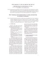
5.4 Performance Results
In this section, we present the performance results for three cases of the movable
boundary (L
c
,L): (I) L
c
=0<L,(II)0<L
c
<Land (III) L
c
= L.An8×8switch
(N = 8) is used in all three cases.
(I) L
c
=0<L. In this case, all traffic channels are used for data packet assignments
only. We present the data packet delay versus the offered packet load for the three
TCAAs presented in Section 5.3. The number of traffic channels is L =8withL
c
=0.
We assume the user population for each uplink beam is M =50, 000 and the buffer
size for each user is B
p
= 10. (New requests are considered lost if the buffer is full).
The probability that a user will transmit a packet in a frame is σ
p
. The packet load
(for each input beam) then is defined as Mσ
p
.
The average packet queuing delays are plotted in Figure 5.8. The results are
obtained by Markovian analysis for the TCAA-1 and by simulations for the TCAA-1
(Optimum), TCAA-2 (Fast/Sub-Optimum) and RTCA (Random). The average delays
are expressed in terms of the number if frames. From the results, we observe that when
THE SS/CDMA THROUGHPUT 123
2t
p
: Round trip propagation delay
t
f
: Frame length or packet length
t
q
: Queing delay of the packet request
α
: Average number of retransmissions of
the packet request over the access
channel (α = 0.01)
T
D
= t
q
+ 2 t
p
+
α
(t
q
+ 2t
p
) + (2t
p
+ t
f
)
2t
p
t
t
Assignment
Response
Access
Requests
t
q
t
f
Figure 5.7 The total data packet delay, T
D
.
Figure 5.8 Packet queuing delay vs. packet load (without any circuit-call load). System
parameters: Lc = 0, L = 8, Bp = 10. The queuing delays are evaluated analytically for
TCAA-1 and by simulation for TCAA-1, -2 and RTCAA.
124 CDMA: ACCESS AND SWITCHING
Figure 5.9 Circuit blocking probability vs. normalized circuit load with circuit call only.
System parameters: Lc = 16, 32, 40, 48. Circuit blocking probabilities are evaluated
analitically.
the traffic load is heavy, the optimum assignment algorithm (TCAA-1) outperforms
the other two algorithms. When the traffic load is light, the fast assignment algorithm
(TCAA-2) gives a performance close to the optimum algorithm. Also, the TCAA-2
packet delay appears to increase rapidly for packet loads above 0.88, due to the greedy
nature of the algorithm when the number of arrivals per frame is large. In addition, we
find that the results obtained from the Markovian analysis and the simulation of the
TCAA-1 are very close, except at a higher packet load (above 0.85). The reason is that
in the simulation, each beam has one buffer of size B
p
, while the analysis combines
the buffer of all beams into one of size NB
p
, which gives a slightly larger delay than
simulation.
(II) 0 <L
c
<L. In this case we consider both circuit and packet calls, and compare
the performances of the three TCAAs. In Figure 5.9, we present the circuit blocking
probabilities versus the normalized circuit load for different circuit call capacities,
L
c
=16, 32, 40, 48. Figure 5.10 shows the blocking probabilities of circuit calls versus
the normalized load of circuit calls. The packet traffic load is fixed at Mσ
p
=0.75.
The probability that an ongoing circuit call will terminate in the next frame, ρ
c
,is
THE SS/CDMA THROUGHPUT 125
Figure 5.10 Circuit blocking probability vs. normalized circuit load when the packet load
is fixed at 0.75. System parameters: Lc = 32, L = 40, Bp = 10.
fixed at 3.333 × 10
−4
, which corresponds to an average circuit call duration of 3000
frames (that is, for frame length 40 ms, the call duration is 2 min). and the probability
that a circuit user will become active, σ
c
, is varied. The circuit traffic load is defined
as Mσ
c
/ρ
c
,whereM = 50000 is the number of circuit users in each uplink beam.
The normalized circuit load is defined as
Mσ
c
/ρ
c
L
c
/N
. The system parameters used are
L
c
= 32, L =40andB
p
= 10. Here we observe that the blocking probabilities for
TCAA-1, TCAA-2 and RTCA obtained from both analysis and simulation are almost
identical. This is due to the fact that circuit calls are much longer than the frame
length, and thus the average number of call arrival or terminations in a frame is very
small. In this case, the optimum and the random TCAA give the same result for code
division switching systems. Figure 5.11 shows the average queueing delays for data
packets versus the normalized circuit load for a fixed value of packet load Mσ
p
=0.75
packets/frame. Here we observe the the packet delay for the RTCA is higher than the
other TCAAs for higher circuit loads.
(III) L
c
= L. This is when circuit calls have pre-emptive priority over packets for
all traffic channels in the pool. In this case, we present the average queueing delays
for data packets versus the normalized circuit load for a fixed value of packet load
Mσ
p
=0.5 packets/frame in Figure 5.12. The system parameters are L
c
= 32, L =32
and B
p
= 10. We observe that packet traffic can be routed through the switch even
126 CDMA: ACCESS AND SWITCHING
Figure 5.11 Packet queuing delay vs. normalized circuit load when packet load is fixed at
0.75. System parameters: Lc = 32, L = 40, Bp = 10. Queuing delays are evaluated
analytically for TCAA-1 and by simulation for TCAA-1, -2 and RTCAA.
when all its capacity is allocated for circuit calls. We also observe that TCAA-1 and
TCAA-2 perform better than the Random TCAA (RTCA).
5.5 Conclusions
In this chapter, we have proposed a Satellite Switched CDMA (SS/CDMA) demand
assignment system which provides multiple access and switching for both voice calls
and data packets. The system operates under the control of channel assignment
algorithms. Three such algorithms have been presented here, an optimum, a sub-
optimum and a random one. Performance analysis and simulation has been carried
out in order to evaluate the switch throughput under the control of the proposed
algorithms.
Performance results indicate that the blocking probabilities for circuit calls under
optimal and random control are almost the same. This is an advantage of the code
division switching method since a computational simple random assignment algorithm
can offer almost the same results as the optimum one. In time multiplexed switching,
on the other hand, a random algorithm has 15% lower throughput of circuit calls than
the optimum one. The data packet delay via the switch has also been evaluated for
THE SS/CDMA THROUGHPUT 127
Figure 5.12 Packet queuing delay vs. normalized circuit load when packet load is fixed at
0.5. System parameters: L = Lc = 32, Bp = 10. Packet delays are evaluated analytically for
TCAA-1 and by simulation for TCAA-1, -2 and RTCAA.
the cases: (I) no traffic channels for circuit calls, (II) traffic channels for both circuit
calls and data packets, and (III) no traffic channels for data packets. In all cases we
observed that the sub-optimum algorithm packet delay is near the optimum one, and
the random one has slightly higher delays, for packet loads of 0.75 or less and for any
circuit load. We also observed that in case (III) where there are no traffic channels for
packets, a packet load of 0.5 can be routed via the switch with limited delays.
References
[1] T. Inukai ‘An efficient SS/TDMA time-slot assignment algorithm’ IEEE
Trans. Commun., Vol. 27, No. 10, October 1979 pp. 1449–1455.
[2] D. Gerakoulis, W-C. Chan and E. Geraniotis ‘Throughput Evaluation of a
Satellite-Switched CDMA (SS/CDMA) Demand Assignment System’ IEEE
J. Select. Areas Commun. Vol. 17, No. 2, February 1999 pp. 286–302.
[3] T.C. Hu Integer Programming and Network Flows. Addison-Wesley,
Massachusetts, 1970.
128 CDMA: ACCESS AND SWITCHING
[4] C. Rose and M.G. Hluchyj ‘The performance of random and optimal
scheduling in a time-multiplex switch’ IEEE Trans. Commun., Vol. 35, No. 8,
August 1987 pp. 813–817.
[5] F. Kelly ‘Blocking probabilities in large circuit-switched networks’ Adv. in
App. Prob., Vol. 18, 1986 pp. 473–505.