Tài liệu CDMA truy cập và chuyển mạch P6 doc
Bạn đang xem bản rút gọn của tài liệu. Xem và tải ngay bản đầy đủ của tài liệu tại đây (479.85 KB, 34 trang )
6
The Spectrally Efficient CDMA
Performance
6.1 Overview
As we have discussed in Chapter 3, the SS/CDMA Traffic channels are based on a
spectrally efficient CDMA (SE-CDMA). The SE-CDMA is designed to reuse each
frequency channel in every satellite beam (frequency reuse one), and also achieve a
very low bit error rate (10
−6
to 10
−10
) at a very low signal-to-noise ratio (E
b
/N
o
).
The low E
b
/N
o
value will allow the use of an Ultra Small Aperture Terminal (USAT)
(antenna dish 26” in diameter), and provide a sufficient margin to mitigate the Output
Back-Off (OBO) at the on-board downlink power amplifier (TWT).
In this chapter we first present the system description and the signal and
channel models (Section 6.2). Then, in Section 6.3, we provide the intra- and
inter-beam interference analysis. In Section 6.4, we examine the on-board signal
processing and the impact of the uplink-downlink coupling. In Section 6.5, we
evaluate the Bit Error Rate (BER) using a concatenated channel encoder and M-
ary PSK modulation. In Section 6.6, we present the performance results, and in
Section 6.7 a discussion the conclusions. This work was originally presented in
reference [1].
6.2 System Description and Modeling
The Traffic channels in the SS/CDMA system carry voice and data directly between
the end subscriber units. The multiple access and the modulation of the traffic
channel is based on the Spectrally Efficient Code Division Multiple Access (SE-CDMA)
scheme, which is analyzed in this chapter. Each SE-CDMA channel is comprised of
three segments: the uplink and downlink channels and the on-board routing circuit.
Both the uplink and downlink are orthogonal CDMA channels. A generalized block
diagram of the SE-CDMA is shown in Figure 3.27 of Chapter 3. The concatenated
channel encoder consists of an outer Reed–Solomon RS(x,y) code (rate y/x) and
an inner Turbo-code with rate k/n.TheTurbo-Code is a parallel concatenation of
recursive systematic convolutional codes linked by an interleaver. The Turbo encoder
output generates n (parallel) symbols which are mapped into the M-ary PSK signal
set (M =2
n
). The signal phases Φ
i
are then mapped into the inphase and quadrature
components (a, b), Φ
i
→ (a, b).
CDMA: Access and Switching: For Terrestrial and Satellite Networks
Diakoumis Gerakoulis, Evaggelos Geraniotis
Copyright © 2001 John Wiley & Sons Ltd
ISBNs: 0-471-49184-5 (Hardback); 0-470-84169-9 (Electronic)
130 CDMA: ACCESS AND SWITCHING
w
1
w
1
w
1
w
1
w
1
w
1
w
1
w
1
w
2
w
2
w
2
w
2
w
2
w
2
w
2
w
2
w
3
w
3
w
3
w
3
w
3
w
3
w
3
w
3
w
4
w
4
w
4
w
4
w
4
w
4
1
2
60
1
23
4
T
c2
T
c1
= 4 x T
c2
T
ss
= 60 x T
c1
L
1
= 60, L
2
= 4
R
c2
= 4 x 2.4576 Mc/s = 9.8304 Mc/s
R
c1
= 60 x 40.96 ks/s = 2.4576 Mc/s
R
ss
= 1/T
ss
= 40.96 ks/s
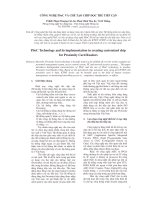
Figure 6.1 The spreading and overspreading symbols for FO/SE-CDMA and the
beam-code re-use over continental USA.
The SE-CDMA spreading operation takes place in two steps. The first step provides
orthogonal separation of all users within the CDMA channel of bandwidth W,and
the second one orthogonal and/or PN code separation between the satellite beams.
Depending on the particular implementation of the spreading process, the SE-CDMA
can be Fully Orthogonal (FO), Mostly Orthogonal (MO) or Semi-Orthogonal (SO).
In all implementations there is orthogonal separation of the users within each beam.
In addition, the FO/SE-CDMA provides orthogonal separation of the first tier of
the satellite beams (four beams). The MO/SE-CDMA has two orthogonal beams in
the first tier, while the SO/SE-CDMA has all beams separated by PN-codes. The
spreading operations for the FO and MO/SE-CDMA are shown in Figure 3.12-A and
for the SO/SE-CDMA in Figure 3.12-B in Chapter 3. The inphase and quadrature
components are spread by the same orthogonal and PN-codes. The FO and MO SE-
CDMA require code generators L
1
and L
2
for the user and the beam separation,
respectively. The first spreading step generates the chip rate R
c1
, and the second
generates the chip rate R
c2
(overspreading). The FO/SE-CDMA has R
c2
=4× R
c1
and the MO/SE-CDMA has R
c2
=2× R
c1
. The (I,Q) PN code generator has a rate
of R
c2
, and is used to isolate the interference from the second tier of beams. The
SO/SE-CDMA spreading consists of L-orthogonal user codes and a PN beam code.
The satellite beams in this case are separated only by the PN code, having a rate of
R
c
= R
c2
.
THE SPECTRALLY EFFICIENT CDMA 131
12 60
1
2
T
c2
T
c1
= 2 x T
c2
T
ss
= 60 x T
c1
L
1
= 60, L
2
= 2
R
c2
= 4 x 4.9152 Mc/s = 9.8304 Mc/s
R
c1
= 60 x 81.92 ks/s = 4.9152 Mc/s
R
ss
= 1/T
ss
= 81.92 ks/s
w
1
w
1
w
1
w
1
w
1
w
1
w
1
w
1
w
2
w
2
w
2
w
2
w
2
w
2
w
2
w
2
w
1
w
2
'
'
w
1
w
2
'
'
w
1
w
2
'
'
w
1
w
2
'
'
w
1
'
w
1
w
2
'
'
w
1
w
2
'
'
w
1
'
W
i
, W
i
'
i = 1, 2 Cross Polarization Isolation
W
1
, W
2
Orthogona Beams
Figure 6.2 The spreading and overspreading symbols for SM/SE-CDMA and the
beam-code re-use over continental USA.
The spreading orthogonal code of length L chips will span over the entire length of
a symbol. Also, in order to maintain the code orthogonality, the SE-CDMA requires
synchronization for the uplink channel. That is, the chips of all orthogonal codes of
the uplink SE-CDMA channel must be perfectly aligned at the satellite despreaders.
The specific SE-CDMA implementations are described in Table 6.1. These are the
Fully Orthogonal (FO-1), the Mostly Orthogonal (MO-1) and the Semi-Orthogonal
(SO-1). In all implementations the outer Reed–Solomon code has a rate of 15/16,
the inner Turbo encoder rate is 2/3 for FO-1, 1/2 for MO-1 and 1/3 for SO-1. The
modulation scheme is 8-PSK for FO-1 and QPSK for MO-1 and SO-1. FO-1 has a
beam code reuse of 1/4, MO-1 1/2 and SO-1 of 1. The above set of parameters has
Tab le 6.1 SE-CDMA selected implementations.
SE-CDMA OUTER INNER MPSK CODE
IMPLEMENT. CODE CODE SCHEME REUSE
FO-1 RS(16λ, 15λ) Turbo, 2/3 8-PSK 1/4
MO-1 RS(16λ, 15λ) Turbo, 1/2 QPSK 1/2
SO-1 RS(16λ, 15λ) Turbo, 1/3 QPSK 1
132 CDMA: ACCESS AND SWITCHING
Tab le 6 .2 Bit, symbol and chip rates for each SE-CDMA
implementation.
RATE FO-1 MO-1 SO-1
R(kb/s) 64 64 64
R
b
(kb/s) 76.8 76.8 76.8
R
s
(ks/s) 81.92 81.92 81.92
R
ss
(ks/s) 40.69 81.92 122.88
R
c1
(Mc/s) 2.4576 4.9152 R
c1
= R
c2
R
c
= R
c2
(Mc/s) 9.8304 9.8304 9.8304
R
c1
/R
ss
60 60 80
R
c2
/R
c1
4 2 1
been selected so that the system capacity is maximized while the BER and E
b
/N
o
are
the lowest possible for the particular implementation.
Table 6.2 shows examples of specific values of the bit, symbol and chip rates for the
FO-1,MO-1andSO-1whenthesourcerateisR = 64 kb/s. Figure 6.1 illustrates
the overspreading operation for the beam reuse pattern FO implementation. The
FO/SE-CDMA provides 60 orthogonal codes for user channels, having a chip rate
of R
c1
=2.4576 Mc/s. Overspreading by a factor of 4 will raise the chip rate to
R
c2
=9.8304 Mc/s, and will provide four orthogonal codes for separating the satellite
beams. The resulting pattern has all beams orthogonal in the first tier, while in the
second tier, beams are separated by PN-codes.
[Rates R, R
b
, R
s
, R
ss
,andR
c
= R
c2
are measured at points shown in Figure 3.7]
The MO/SE-CDMA has a similar implementation. The spreading rate on the
first step is R
c1
=4.9152 Mc/s. The overspreading rate is R
c2
=2× R
c1
,and
provides, two orthogonal codes for beam isolation. In the resulting pattern, four
out of six beams in the first tier are orthogonally isolated, and two by cross-
polarization and PN-codes. (Cross-polarization will be used for further reduction of
the other beam interference in this case.) Figure 6.2 illustrates the overspreading
and the beam reuse pattern for MO/SE-CDMA. In the SO/SE-CDMA the spreading
operation has the user orthogonal code and the beam I and Q PN codes. All
codes have the same rate R
c
=9.8304 Mc/s. Beams are only separated by PN
codes.
Following the spreading operation, the resulting I and Q waveforms will be band-
limited by a digital FIR filter. The FIR filter is a Raised Cosine filter with a roll-off
factor of 0.15 or more. After the digital filter the signal will be converted into analog
form and modulated by a quadrature modulator, as shown in Figure 3.11. The resulting
IF signal bandwidth will be W (W ≈ 10MHz).
The SE-CDMA receiver is illustrated in Figure 6.3. The chip synchronization and
tracking for despreading the orthogonal and PN codes is provided by a mechanism
specifically developed for this system which is presented in Chapter 7. This analysis,
THE SPECTRALLY EFFICIENT CDMA 133
~
cos(2
π
f
0
t)
π/2
sin(2
π
f
0
t)
LPF A/D FIR
D
E
S
P
R
E
A
D
E
R
LPF A/D FIR
a = cos
Φ
i
b = sin
Φ
i
Φ
i
=
−
tan
1
b
a
LEVEL
MAPPING
REED
SOLOMON
DECODER
Data
TURBO
DECODER
PHASE
ESTIMATOR
Aid Symbols
a =
=
cos
Φ
i
b sin
Φ
i
Figure 6.3 The SE-CDMA receiver.
however, will assume perfect chip synchronization at the despreader. Coherent
detection will also be provided using reference or aid symbols. The aid symbols that
have a known phase are inserted at the transmitter at a low rate and extracted at
the receiver in order to provide the phase estimates for the information symbols.
The analysis in this paper, however, will consider ideal coherent detection. The
channel decoding for the Reed–Solomon and Turbo codes will only take place at the
receiver of the end user. On board the satellite we consider three possible options:
(a) baseband despreading-respreading without demodulation or channel decoding;
(b) baseband despreading-respreading with demodulation but not channel decoding;
and (c) Intermediate Frequency (IF) despreading-respreading without demodulation
or channel decoding. However, the analysis and numerical results presented in this
paper are limited only to case (a).
6.2.1 Signal and Channel Models
In this subsection we provide a brief description of the signal and channel model.
The signal model includes the data and spreading modulation, while the channel is
described by a ‘Rician’ flat fading model.
134 CDMA: ACCESS AND SWITCHING
∫
L
2
T
c2
0
C
O
H
E
R
E
N
T
D
E
M
O
D
U
L
A
T
O
R
W
i
(t)
W
k
(t)
∫
L
2
T
c2
0
∫
L
1
T
c1
0
∫
L
1
T
c1
0
L
1
T
c1
L
2
T
c2
L
2
T
c2
L
1
T
c1
C
H
A
N
N
E
L
D
E
C
O
D
E
R
Despreader
g
i
a)
C
O
H
E
R
E
N
T
D
E
M
O
D
U
L
A
T
O
R
w
k
(t)
∫
LT
c
0
∫
LT
c
0
LT
c
LT
c
C
H
A
N
N
E
L
D
E
C
O
D
E
R
DATA
Despreader
g
i
b)
Figure 6.4 The despreading operations for (a) FO and MO/SE-CDMA, and (b)
SO/SE-CDMA.
Data Modulation
The transmitted signal from the k
th
user is
s
k
(t)=
2P
k
b
(k)
I
(t)c
(k)
I
(t)cos[ω
u
c
t + θ
(k)
]+b
(k)
Q
(t)c
(k)
Q
(t) sin[ω
u
c
t + θ
(k)
]
where P
k
is the transmitted power of the k
th
signal (this includes transmitter antenna
gains and power control); ω
u
c
=2πf
u
c
is the frequency carrier of the system for the
uplink (actually it corresponds to the center frequency of one of the 10 MHz channels)
θ
(k)
is the phase angle of the k
th
signal (user) local oscillator. It is modeled as a slowly
changing random variable uniformly distributed in [0, 2π].
The data waveforms b
(k)
I
(t)andb
(k)
Q
(t)aregivenby
b
(k)
I
(t)=
∞
n=−∞
b
(k)
I
[n]p
T
s
(t − nT
s
)
b
(k)
Q
(t)=
∞
n=−∞
b
(k)
Q
[n]p
T
s
(t − nT
s
)
THE SPECTRALLY EFFICIENT CDMA 135
and represent the inphase and quadrature components of the data waveform (sequence
of M-ary symbols) of the k
th
user. In this notation p
T
s
(t) is a rectangular pulse
of duration T
s
, and the symbol duration; T
s
= (log
2
M)T
b
,whereT
b
is the bit
duration (this relationship is modified later in the paper due to the Turbo inner
coding and the RS outer coding used).
b
(k)
I
[n],b
(k)
Q
[n]
are defined to be the inphase
and quadrature components of the n
th
M-ary symbol of the k
th
user. They are defined
as b
(k)
I
[n]=cosφ
(k)
[n]andb
(k)
Q
[n]=sinφ
(k)
[n], where φ
(k)
[n] denotes the phase angle
of the n
th
M-ary symbol of the k
th
signal (user); they take values in the sets
b
(k)
I
[n] ∈
cos
(2m − 1)π
M
,m=1, 2, ,M
b
(k)
Q
[n] ∈
sin
(2m − 1)π
M
,m=1, 2, ,M
It is assumed that the sequences of phase angles (symbols) φ
(k)
[n]ofthek =
1, 2, ,K signals are i.i.d, i.e. independent for different n (symbols) and for different
k (signals/users), and are identically distributed. With respect to the latter, it is
assumed that the phase angle φ
(k)
[n]ofthen
th
symbol of the k
th
signal is uniformly
distributed in the set {π/M,3π/M, ,(2M − 1)/M }, and subsequently the inphase
and quadrature components b
(k)
I
[n]andb
(k)
Q
[n] are i.i.d (for different k and n)and
uniformly distributed (take each value with equal probability 1/M )intheabovesets.
For the same k and n, b
(k)
I
[n]andb
(k)
Q
[n] are not independent of each other, but are
uncorrelated; thus we can easily show that the expected value over the above sets
results in
E
b
(k)
I
[n]b
(k)
Q
[n]
=0and E
b
(k)
I
[n]
2
= E
b
(k)
Q
[n]
2
=
1
2
CDMA Spreading Modulation
For a CDMA system using inphase and quadrature codes c
(k)
I
[l]andc
(k)
Q
[l]wehave
c
(k)
I
(t)=
∞
l=−∞
c
(k)
I
[l]g
T
c
(t − lT
c
)c
(k)
Q
(t)=
∞
l=−∞
c
(k)
Q
[l]g
T
c
(t − lT
c
)
The chip shaping waveform, which takes values
g
T
c
(t)=sinc(W
ss
t)
cos(πρW
ss
t)
1 − 4ρ
2
W
2
ss
t
2
for all t
where sin c(x)=sin(πx)/(πx), W
ss
=1/T
c
(for SO/SE-CDMA) or W
ss
=1/T
cc
(for
FO/SE-CDMA and MO/SE-CDMA) is the total spread signal bandwidth, and g(t)
has as a Fourier Transform the raised cosine pulse (in the frequency domain)
G(f)=
1
W
ss
for |f| <f
1
1
2W
ss
1+cos
π(|f|−f
1
)
W
ss
− 2f
1
for f
1
< |f| <W
ss
− f
1
G(f)=0for|f| >W
ss
− f
1
.
136 CDMA: ACCESS AND SWITCHING
This represents the transfer function of the chip filter used at the transmitter to
band-limit the spread-spectrum signal. The parameter f
1
is related to ρ,theroll-off
factor,andthetotal one-sided bandwidth for the chip filter as
ρ =1−
2f
1
W
ss
,W
F
c
= W
ss
− f
1
=(1+ρ)
W
ss
2
For example, for a roll-off factor of ρ =0.15 (15%), the two-sided bandwidth of the
chip filter is given by 2W
F
c
=1.15W
ss
.
For the SO/SE-CDMA system there is one chip duration T
c
and one processing
gain (due to spreading) L (chips per symbol) such that T
s
= LT
c
.Inthissystem
c
(b
k
)
[l] is the unique PN code (the beam address) characterizing beam b
k
,where
b
k
∈{1, 2, ,N} is the index of the beam at which the k
th
user resides, and
w
(k)
I
[l],w
(k)
Q
[l]
is the pair of orthogonal codes (Quadrature Residue) assigned to
user k; these codes are reused in each of the N beams. In this case we can write
c
(k)
I
(t)=
∞
l=−∞
w
(k)
I
[l]c
(b
k
)
[l]g
T
c
(t − lT
c
)c
(k)
Q
(t)=
∞
l=−∞
w
(k)
Q
[l]c
(b
k
)
[l]g
T
c
(t − lT
c
)
If only one orthogonal code per user is used, then w
(k)
I
[l]=w
(k)
Q
[l] for all l, and thus
c
(k)
I
(t)=c
(k)
Q
(t) for all t.
For the FO/SE-CDMA and MO/SE-CDMA systems there are two chip durations T
c
and T
cc
corresponding to the two stages of spreading. Besides the PN beam code c
(b
k
)
[l]
and the pair of orthogonal user codes
w
(k)
I
[l],w
(k)
Q
[l]
, there is a Walsh orthogonal
code w
(b
k
)
[m] assigned to beam b
k
. The following relationships are now true:
T
s
= L
u
T
c
and T
c
= L
b
T
cc
where L
u
(user chips per symbol) and L
b
(beam chips per user chip) are the two
processing (spreading) gains, and
L = L
u
L
b
is the total spreading gain. There are two possible choices for L
b
= 2 corresponding to
MO/SE-CDMA and L
b
= 4 corresponding to FO/SE-CDMA. There are L
b
orthogonal
beam codes, and these codes are re-used between the N beams, as shown in Figure 6.1
for FO/SE-CDMA and in Figure 6.2 for MO/SE-CDMA. In this case, we can write
c
(k)
I
(t)=
∞
l=−∞
w
(k)
I
[l]c
(b
k
)
[l]
(l+1)L
b
−1
m=lL
b
w
(b
k
)
[n]g
T
cc
(t − mT
cc
)
where g
T
cc
(t−mT
cc
)isthesameasg
T
c
(t−mT
c
) above, with T
cc
replacing T
c
. Similarly,
c
(k)
Q
(t)=
∞
l=−∞
w
(k)
Q
[l]c
(b
k
)
[l]
(l+1)L
b
−1
m=lL
b
w
(b
k
)
[m]g
T
cc
(t − mT
cc
)
We may have c
(k)
Q
(t)=c
(k)
I
(t) if each user uses only one orthogonal code.
THE SPECTRALLY EFFICIENT CDMA 137
The Channel Model
The K
a
band SATCOM channel is well approximated by a flat fading channel having
a standard Rician pdf p(x)=
x
σ
2
exp
−
x
2
+µ
2
2σ
2
I
0
µx
σ
2
or equivalently the pdf
p(r)=
2(K
f
+1)r
S
2
exp
−(K
f
+1)
r
2
S
2
− K
f
I
0
2
r
S
K
f
(K
f
+1)
where
K
f
=
µ
2
2σ
2
S
2
= E{X
2
} = µ
2
+2σ
2
=
K
f
+1
K
f
µ
2
=(K
f
+ 1)(2σ
2
)
is the ‘Rician factor’ equal to the ratio of the power in the LOS (line of sight) path
(µ
2
) and the power in the reflected paths (2σ
2
), and S
2
is the total received power in
the LOS and reflected paths.
Rain fade statistics determine the values of the parameters. Under severe rain fades
the channel model will be better approximated by a Raleigh pdf (special case of the
above for µ =0=K
f
). There is no delay spread in this flat fading channel model. We
assume that all signals are fading independently and according to the above Rician
distribution (with the same parameters for all signals).
In our analysis and numerical results we assumed that the SATCOM channel
is equivalent to an AWGN channel. This approximation is only good for clear-sky
conditions, but allows us to focus on the effects of other-user interference (intra-beam
and other-beam) of the system under full-load (high capacity conditions).
The analysis of this chapter can be easily modified to account for the Rician fading
model above. Specifically, the variance of all other-user interference terms should be
multiplied by the factor 1 +
1
K
f
(or its square for cross-terms of interference, see
Section 6.5), and the final expression for the Bit Error Rate (BER) of the user of
interest should be obtained by first conditioning on the Rician amplitude and then
integrating with respect to the Rician distribution. However, this was not included
in the chapter due to space limitations, and because of the selected emphasis of the
paper on other-user interference issues.
6.3 Interference Analysis
In this section we first evaluate the cross-correlation functions of the CDMA codes of
the interfering users from the various beams. Then we compute the power of other-
user interference, assuming that perfect power control is employed to calibrate for the
different received signal strengths of the user signals.
6.3.1 Cross-correlation of Synchronous CDMA Codes
Under fully synchronous system operation (time-jitter = 0) the normalized (integrated
over the period of one symbol) cross-correlation between different users takes the form
C
k,i
=
1
L
L−1
l=0
w
(k)
[l]w
(i)
[l]c
(b
k
)
[l]c
(b
i
)
[l]
138 CDMA: ACCESS AND SWITCHING
for SO/SE-CDMA and
C
k,i
=
1
L
u
L
b
L
u
−1
l=0
w
(k)
[l]w
(i)
[l]c
(b
k
)
[l]c
(b
i
)
[l]
(l+1)L
b
−1
m=lL
b
w
(b
k
)
[m]w
(b
i
)
[m]
for FO/SE-CDMA and MO/SE-CDMA.
Code Cross-correlation for SO/SE-CDMA
Recall that for the SO/SE-CDMA system T
s
= LT
c
.Letb
k
and b
i
be the beams that
users k and i reside in. If b
k
= b
i
,k = i (users in the same beam), then
C
k,i
=
1
L
L−1
l=0
w
(k)
[l]w
(i)
[l]=0
since the codes are orthogonal (Quadrature Residue); see Chapter 2. If instead, Quasi-
Orthogonal (QO) preferred phase Gold codes (see Chapter 2) are used, we have
C
k,i
=
1
L
L−1
l=0
w
(k)
[l]w
(i)
[l]=
1
L
· 1=
1
L
If b
k
= b
i
,k = i (users in different beams), the concatenation of orthogonal (or quasi-
orthogonal) user codes and PN beam codes results in codes that have (approximately)
PN properties, and thus
E{C
k,i
} =0and Var{C
k,i
} =
1
L
where the averages are taken with respect to the PN sequence taking values +1 and
−1 with equal probability and independently from chip to chip, and from user to user
(different users). This is the random sequence model of PN sequences that has been
widely used in the literature; it is very accurate when L is large (larger than 30).
In conclusion, for the SO/SE-CDMA system and two users k and i we have
E{C
2
k,i
} =
0 k and i in same beam, orthogonal codes used
1
L
2
k and i in same beam, quasi-orthogonal codes used
1
L
k and i in different beams, all codes used
Here we assumed that the same polarization is used over all of the beams.
Code Cross-correlation for FO/SE-CDMA and MO/SE-CDMA
Recall that for the FO/SE-CDMA (and MO/SE-CDMA) system T
s
= L
u
T
c
and
T
c
= L
b
T
cc
. Again let b
k
and b
i
be the beams that users k and i reside in. If
b
k
= b
i
,k = i (k and i in the same beam), we have
C
k,i
=
1
L
u
L
u
−1
l=0
w
(k)
[l]w
(i)
[l]=
0 k and i in same beam, orthogonal codes used
1
L
u
k and i in same beam, quasi-orthog. codes used
THE SPECTRALLY EFFICIENT CDMA 139
If b
k
= b
i
,k = i (k and i in different beams) we must distinguish between the first
tier of beams b
k
surrounding beam b
i
and the second tier of beams b
k
surrounding
beam b
i
.
For FO/SE-CDMA all first-tier beams use distinct orthogonal codes (for
overspreading), and thus
L
b
−1
n=0
w
(b
k
)
[n]w
(b
i
)
[n] = 0 because of the code reuse factor
of 4. Thus
C
k,i
=0, if b
k
is a first-tier beam surrounding beam b
i
For MO/SE-CDMA, half of them use a distinct orthogonal code, the other half use
the same orthogonal code but different polarization (than the beam of interest), so
interference from them is not 0, but rather it is the same as PN-type interference
(since the concatenation of the (orthogonal or quasi-orthogonal) user code and the
PN (address) beam code is (approximately) equivalent to a PN code) but lower by 6
db (=1/4 of the power of the beam of interest) for a polarization isolation of 6 dB.
Thus, for MO/SE-CDMA, considering b
k
to be a second-tier beam with respect to
beam b
i
,wehave
E{C
2
k,i
} =
1
L
u
using the same beam code and same polarization
1
4L
u
using the same beam code and different polarization
0 uses a different beam code
Both of the above results are independent of the user codes w
(k)
and w
(i)
being
orthogonal or quasi-orthogonal.
Similarly, for the second-tier beams we have for either FO/SE-CDMA or MO/SE-
CDMA (no distinction now)
E{C
2
k,i
}=
1
L
u
using the same beam code and same polarization
1
4L
u
that using the same beam code and different polarization
0 using a different beam code
6.3.2 Normalized Power of Other-User Interference
Analysis of Interference at the Matched Filter Output
In computing the variance of the interference caused to user i by any other user k,we
note that the input to a correlation receiver (coherent demodulator) for M-ary PSK
modulation takes the form
r
u
(t)=s
u
i
(t)+
k=i
s
u
k
(t)+n
u
(t)
=
2P
u
i
b
(i)
I
(t)c
(i)
I
(t)cos[ω
u
c
t + θ
(i)
]+
k=i
2P
u
k
b
(k)
I
(t)c
(k)
I
(t)cos[ω
u
c
t + θ
(k)
]
+
2P
u
i
b
(i)
Q
(t)c
(i)
Q
(t) sin[ω
u
c
t + θ
(i)
]+
k=i
2P
u
k
b
(k)
Q
(t)c
(k)
Q
(t) sin[ω
u
c
t + θ
(k)
]
+ n
u
(t)
where n
u
(t) is a Gaussian noise process (AWGN) with zero mean and two-sided
spectral density
1
2
N
0
. P
u
k
is the received uplink power at the satellite receiver; it
140 CDMA: ACCESS AND SWITCHING
includes the propagation and flat fading losses (no multipath or delay spread), the
satellite receiver antenna gain, and of course, the transmitted power P
k
.
At this point it is assumed that the correlation receiver performs baseband
processing of the signal (despreading and coherent demodulation). In this sense this
analysis is valid for the uplink of the GEO SATCOM system (despreading and
demodulation take place onboard the satellite), provided that the transmitted powers
are appropriately adjusted. However, for the subsequent analysis of this section to be
valid for the downlink (despreading and demodulation take place at the user receiver),
we must assume that full regeneration of the signal takes place on board the satellite,
and thus the uplink and downlink performances are decoupled (except for the cascade
AWGN noise). These issues are revisited and discussed in full detail in Section 6.4,
where one of the on-board processing options is modeled and analyzed.
Under these conditions, the inphase and quadrature components of the output of
the i
th
correlation receiver take the form
Z
(i),u
I
=
T
s
0
r
u
(t)c
(i)
I
(t)2 cos[ω
u
c
t + θ
(i)
]dtZ
(i),u
Q
=
T
s
0
r
u
(t)c
(i)
Q
(t)2 sin[ω
u
c
t + θ
(i)
]dt
respectively. It is assumed that the receiver is in perfect time, frequency and phase
synchronization with the i
th
transmitter, and that the demodulation of the 0
th
symbol
of duration T
s
= LT
c
for SO/SE-CDMA (or T
s
= L
u
L
b
T
cc
for FO/SE-CDMA and
MO/SE-CDMA) is performed. Thus, without loss of generality, we can assume that
θ
(i)
= 0. Let us define N
u
I
as the noise component at the output of the inphase branch
of the correlator as N
u
I
=
T
s
0
n
u
(t)2 cos(ω
u
c
t)dt. Using the above decomposition of the
received signal r(t) in inphase and quadrature components, assuming (as is typical
in DS/CDMA systems) that ω
u
c
T
c
>> 1sothat
sin(ω
u
c
T
c
)
ω
u
c
T
c
<< 1, and performing the
integrations, we obtain
Z
(i),u
I
=
2P
u
i
T
s
b
(i)
I
[0]
+
k=i
2P
u
k
T
s
b
(k)
I
[0] cos[θ
(k)
]
1
L
L−1
l=0
w
(k)
I
[l]w
(i)
I
[l]c
(b
k
)
[l]c
(b
i
)
[l]
+b
(k)
Q
[0] sin[θ
(k)
]
1
L
L−1
l=0
w
(k)
Q
[l]w
(i)
I
[l]c
(b
k
)
[l]c
(b
i
)
[l]
+ N
u
I
A similar development provides the quadrature component Z
(i),u
Q
, which we omit here.
Next we evaluate the first and second moments of Z
(i),u
I
and Z
(i),u
Q
with respect to
the phase angle θ
k
of the local oscillator of user k (1 ≤ k ≤ K, k = i) and its M-ary
PSK symbols b
(k)
I
[0] and b
(k)
Q
[0]. First, we use the fact that averaging with respect to
θ
(k)
gives E {cos θ
k
sin θ
k
} =0andE
cos
2
θ
k
= E
sin
2
θ
k
=
1
2
to obtain for the
THE SPECTRALLY EFFICIENT CDMA 141
squares of desired (inphase and quadrature) signal terms
D
(i),u
I
2
=
E
Z
(i),u
I
2
=(2P
u
i
)T
2
s
[b
(i)
I
[0]]
2
D
(i),u
Q
2
=
E
Z
(i),u
Q
2
=(2P
u
i
)T
2
s
[b
(i)
Q
[0]]
2
and for the variance of other-user interference
Var
Z
(i),u
I
=
1
4
k=i
(2P
u
k
)T
2
s
1
L
L−1
l=0
w
(k)
I
[l]w
(i)
I
[l]c
(b
k
)
[l]c
(b
i
)
[l]
2
+
1
L
L−1
l=0
w
(k)
Q
[l]w
(i)
I
[l]c
(b
k
)
[l]c
(b
i
)
[l]
2
+ N
0
T
s
A similar expression is valid for Var
Z
(i),u
Q
(omitted). If every user is assigned
a single orthogonal code, i.e. w
(k)
Q
[l]=w
(k)
I
[l] for all k =1, 2, ,K,theabove
expressions simplify further to
Var
Z
(i),u
I
= Var
Z
(i),u
Q
=
1
2
k=i
(2P
u
k
)T
2
s
E{C
2
k,i
} + N
0
T
s
where
C
k,i
=
1
L
L−1
l=0
w
(k)
I
[l]w
(i)
I
[l]c
(b
k
)
[l]c
(b
i
)
[l]
and E{C
2
k,i
} was as evaluated in Section 6.3. Notice that the above calculations were
conducted for the SO/SE-CDMA system. They are all also valid for the FO/CDMA
system if we replace terms like
1
L
L−1
l=0
w
(k)
I
[l]w
(i)
I
[l]c
(b
k
)
[l]c
(b
i
)
[l] by the corresponding
terms
1
L
u
L
u
−1
l=0
w
(k)
I
[l]w
(i)
I
[l]c
(b
k
)
[l]c
(b
i
)
[l]
1
L
b
L
b
−1
n=0
w
(b
k
)
[n]w
(b
i
)
[n] which involve the
orthogonal beam codes w
(b
k
)
[n]andw
(b
i
)
[n]ofthebeamsb
k
and b
i
, respectively, where
the users k and i reside.
Thus if we normalize the variance (power) of the other-user interference by the
power of the desired signal, we obtain the normalized interference power
Var
Z
(i),u
I
= Var
Z
(i),u
Q
=
1
2
k=i
P
u
k
P
u
i
C
2
k,i
+
N
0
T
s
2P
u
i
=
1
2
k=i
P
u
k
P
u
i
C
2
k,i
+
2E
u
s
N
0
−1
for the I and Q branches of the correlation receiver, with E
u
s
and E
u
b
E
u
s
= P
u
i
T
s
= P
u
i
(log
2
M)T
b
= (log
2
M)E
u
b
as the (received at uplink) energy per symbol and energy per bit of the signal,
respectively.
142 CDMA: ACCESS AND SWITCHING
Therefore, observing that E{C
2
k,i
} (Section 6.3.5) is basically independent (for large
user populations) of the specific pair (k, i)ofusercodes,weobtain
ˆ
I
u
=
k=i
P
u
k
P
u
i
¯
I
s
+
2E
u
s
N
0
−1
We represent the (power of the) interference caused by one user to another by
¯
I
s
as
if they had the same power. The factor
k=i
P
u
k
P
u
i
which depends on power control is
evaluated in detail in Section 6.3.3. Using these results, we next derive the values of
¯
I
s
.
Power of Interference from Single User for SO, FO and MO/SE-CDMA
The power of interference from a single user in a SO/SE-CDMA system is given by
¯
I
s
=
0 if interfering user in same beam, orthogonal user codes
1
2L
2
if interfering user in same beam, preferred Gold codes
1
2L
if interfering user in different beam, any type of user code
where L is the processing gain due to spreading (number of chips per user symbol),
and only one type of polarization is used over all beams.
Similarly, the power of interference from a single interfering user in a FO/SE-CDMA
system is given by
¯
I
s
=
0 interfering user in same beam, orthogonal user codes
1
2L
2
u
interfering user in same beam, preferred Gold codes
0 interfering user in first tier surrounding beam
1
2L
u
user in second tier beam with same beam code and same polarization
1
8L
u
user in second tier beam with same beam code but different polarization
0 user in second tier beam with different beam code
where L
u
is the processing gain due to user spreading (number of user chips per user
symbol).
Finally, the power of interference from a single user in a MO/SE-CDMA system is
given by
¯
I
s
=
0 interfering user in same beam, orthogonal user codes
1
2L
2
u
if interfering user in same beam, preferred Gold codes
0 interfering user in any tier surrounding beam with different beam code
1
2L
u
user in any tier beam with same beam code and same polarization
1
8L
u
user in any tier beam with same beam code but different polarization
6.3.3 Effects of Power Control on Interference
In this section we incorporate the effects of power control and location of users on
other-user interference. Center-of-beam (boresight) antenna gains, propagation losses,
and attenuation due to flat fading (with no frequency or time selectivity) have not
THE SPECTRALLY EFFICIENT CDMA 143
r
r’
2R
θ
r’
r
4R
θ
Beam-0
Beam-j Beam-j’
0
φ
j
φ
User
Beam-0
Beam-j (Tier-1)
Beam-j
’
(Tier-2)
A
B
Figure 6.5 (A) The antenna pointing angle to a user in beam j from beam 0. (B) The
geometry of the antenna pattern in beams 0, j and j’.
been taken into consideration in this analysis, which is performed under clear-sky con-
ditions, since they only add or subtract dBs to or from the E
b
/N
0
(in dB) required
to achieve a particular BER value. However, we do actually evaluate the average
E{P
u
k
/P
u
i
} (refer to section 6.3.2) of the ratio of the received powers of the k
th
inter-
fering user and i
th
(desirable) user with respect to the user location in the beams, and
after power control and satellite antenna beam patterns (transmit and receive) have
been taken into account.
Notation
First we introduce the transmitter and receiver antenna power gain functions of the
satellite, and of the user receiver (CPE, or Customers Premises Equipment):
G
t
(φ) = satellite transmit antenna power gain function
G
r
(φ) = satellite receive antenna power gain function
144 CDMA: ACCESS AND SWITCHING
ˆ
G
t
(φ) = CPE transmit antenna gain power function
ˆ
G
r
(φ) = CPE receive antenna power gain function
These functions are provided in Appendix 6A.
Next we introduce all of the necessary satellite pointing angles (called stereo
angles), distances and planar angles that are involved in modeling and evaluating
the interference caused to the user of interest (assumed to be in the footprint of beam
0) from another user located in the footprint of beam j (see Figure 6.5):
φ
(0)
0
= stereo angle to user of interest in beam 0 with respect to center of beam 0
φ
(j)
0
= stereo angle to interfering user in beam j with respect to center of beam 0
φ
(0)
j
= stereo angle to user of interest in beam 0 with respect to center of beam j
φ
(j)
j
= stereo angle to interfering user in beam j with respect to center of beam j
θ
(0)
0
= planar angle of user of interest in beam 0 with respect to center of beam 0
θ
(j)
0
= planar angle of interfering user in beam j with respect to center of beam 0
r
(0)
0
= distance of user of interest in beam 0 from the center of beam 0
r
(j)
0
= distance of interfering user in beam j from the center of beam 0
r
(0)
j
= distance of user of interest in beam 0 from the center of beam j
r
(j)
j
= distance of interfering user in beam j from the center of beam j
Refer to Figure 6.5-A for the implied beam architecture. The pointing angles and
distances shown in Figure 6.5-B pertain to the interfering user (residing in beam j),
that is φ
0
= φ
(j)
0
, φ
j
= φ
(j)
j
, r = r
(j)
0
and r
= r
(j)
j
.
It is assumed that all beam footprints are approximated by circles of radius
R = 256 km, and the distance of the GEO satellite from the center of all beams is
D
0
=35, 786 km equal to the distance from the earth’s surface; that is, the curvature
of the earth is not taken into account.
We further assume that both the user of interest (in beam 0) and the interfering
user (in beam j) are drawn from populations that can be modeled with the simple
location model of Appendix 6A.
Uplink Power Control and Other-User Interference
Let us assume that the normalized transmitted power from any CPE is P
t
, together
with the transmit antennae gain P
t
ˆ
G
t
. Then at the satellite receive antennae of beam
0, the received power for the signal of the user of interest is P
t
ˆ
G
t
·G
(0)
r
φ
(0)
0
·(λ/4π)
2
,
while the power of an interfering user in beam j received at the antenna of beam 0
is P
t
ˆ
G
t
· G
(0)
r
φ
(j)
0
· (λ/4π)
2
, where we have used the definitions of pointing angles
above. Notice that the received power of the useful signal varies with its location
within beam 0.
This undesirable variation can be eliminated (or at least mitigated) if we assume
that a power control scheme (open-loop) is used, according to which the transmitted
THE SPECTRALLY EFFICIENT CDMA 145
power from each user’s CPE is inversely proportional to the satellite receive antenna
gain for the satellite pointing angle to that user. In this case the user of interest
transmits
P
t
G
(0)
r
(φ
(0)
0
)
ˆ
G
t
and the interfering user transmits
P
t
G
(j)
r
(φ
(j)
j
)
ˆ
G
t
. Therefore, these
two signals are received at the receive antenna of beam 0 as P
t
ˆ
G
t
(λ/4π)
2
and
P
t
ˆ
G
t
(λ/4π)
2
G
(0)
r
(φ
(j)
0
)
G
(j)
r
(φ
(j)
j
)
, respectively.
Clearly, the received power of the useful signal is now independent of the location
of the user within beam 0, and the ratio of received interference power to received
useful signal power (= normalized interference) is
G
(0)
r
(φ
(j)
0
)
G
(j)
r
(φ
(j)
j
)
, which depends upon the
pointing angles φ
(j)
0
and φ
(j)
j
on the distances r
(j)
0
and r
(j)
j
(see Appendix 6A) of the
interfering user from the centers of the footprints of beam 0 and beam j, respectively.
From these two distances, r
(j)
0
varies in the range R ≤ r
(j)
0
≤ 3R for a first-tier beam
j andintherange3R ≤ r
(j)
0
≤ 5R for a second-tier beam j, while r
(j)
j
is evaluated
from r
(j)
0
and from θ
(j)
0
according to the formulas of Appendix 6A.
Notice that the transmitter and receive antennae gain functions
ˆ
G
t
(φ)and
ˆ
G
r
(φ)of
the CPE do not come into the interference (and BER) evaluation, because the CPE
transmitter and receiver are viewed as a single point (dimensionless or point sources)
from the satellite due to the enormous distance between the GEO satellite and the
CPE. However, the transmitter and receive antennae gains in the centers of the beams
ˆ
G
t
(0) =
ˆ
G
t
and
ˆ
G
r
(0) =
ˆ
G
r
do come into the calculation.
Taking the average with respect to all possible locations of the (single) interfering
user in a first-tier beam gives
¯
I
u
1
= Var{I
u,(j)
1
} = E
P
u
k
P
u
i
=
1
πR
2
π/6
−π/6
3R
R
G
(0)
r
φ
(j)
0
r
(j)
0
,θ
(j)
0
G
(j)
r
φ
(j)
j
r
(j)
0
,θ
(j)
0
r
(j)
0
dr
(j)
0
dθ
(j)
0
for a user k belonging to first-tier beam j interfering with user i of beam 0 and
¯
I
u
2
= Var{I
u,(j)
2
} = E
P
u
k
P
u
i
=
1
πR
2
π/12
−π/12
5R
3R
G
(0)
r
φ
(j)
0
r
(j)
0
,θ
(j)
0
G
(j)
r
φ
(j)
j
r
(j)
0
,θ
(j)
0
r
(j)
0
dr
(j)
0
dθ
(j)
0
for a user k belonging to the second-tier beam j interfering with user i of beam 0.
The functions G(·) are obtained from Appendix 6A. Owing to symmetry, the above
integrals are the same for all beams j =1, 2, ,6 of the first tier or all beams
j =1, 2, ,12 of the second tier.
To the above equations we must now add the power of interference from a single user
in the same beam 0 as the user of interest. Although the fully synchronous SO, FO
and MO-SE/CDMA systems avoid intra-beam (same beam) interference through the
use of orthogonal (quadrature-residue) codes, such interference from users in the same
beam is present due to time-jitter resulting from inaccuracies in the synchronization
algorithm. Arguments such as those used above for evaluating the interference power
from beams j of the first or second tiers can be used to show that
¯
I
u
0
= Var{I
u,(0)
0
} =1,
146 CDMA: ACCESS AND SWITCHING
since the application of the power control law will now give
G
(0)
r
(φ
(∗)
0
)
G
(0)
r
(φ
(∗)
0
)
=1,whereφ
(∗)
0
is the pointing angle from the satellite to a user ∗ in beam 0. Notice that, although
the distance of the user of interest and of user ∗ from the center of the beam footprint
are different, their distance from the satellite is practically the same, so that distance-
based (rather than pointing angle-based) power control has no effect on the received
power at the satellite.
To obtain the total normalized interference power from all K users of a beam j
while taking the properties of the CDMA codes into account, we must make use of
the expression for
¯
I
s
cited at the end of Section 6.3.2. The total interference from any
single first-tier beam or any single second-tier beam is then obtained by multiplying
¯
I
u
1
and
¯
I
u
2
, respectively, by K
¯
I
s
. Similarly, the total interference from beam 0 (if at
all present) is obtained as (K −1)
¯
I
s
(since
¯
I
u
0
= 1); only if PN-codes are used is this
non-zero; it is zero for the SO, FO and MO/SE-CDMA systems of this paper.
Total Uplink Interference Power for SO, FO and MO/SE-CDMA
The final expression of the total normalized variance (power) of the other-user
interference from all adjacent beams now depends on the CDMA system in question.
For the SO/SE-CDMA system under fully synchronous conditions we get no
interference from the same beam and PN-type interference from the adjacent beams
of the first and second tiers. Thus, if the same polarization is used for the signal of all
beams, the total other-user interference power
¯
I
u
0,t
becomes
¯
I
u
0,t
= K
¯
I
s
6
j=1
Var{I
u,(j)
1
} +
12
j=1
Var{I
u,(j)
2
}
=
K
2L
6
¯
I
u
1
+12
¯
I
u
2
provided all first and second tier beams are involved in the coverage of a particular
area; otherwise, only those beams involved in coverage must be accounted for in the
factors 6 and 12 of the above equation. For example, for coverage of CONUS by 30–32
beams, a maximum of 8 (rather than 12) second-tier beams are surrounding one beam
(worst case), resulting in
¯
I
u
0,t
=
K
2L
6
¯
I
u
1
+8
¯
I
u
2
If half of the beams use different polarization from the other half, a 6 dB (= of 1/4)
isolation factor is introduced, and the power of interference is
¯
I
u
0,t
=
K
2L
3.75
¯
I
u
1
+5
¯
I
u
2
where the factors 3.75 = 3 ·1+3·
1
4
and 5 = 4 ·1+4·
1
4
account for the use of different
polarization by half of the beams.
Similarly, for FO/SE-CDMA under fully synchronous conditions, we get no
interference from the same beam, no interference from the adjacent first tier beams,
THE SPECTRALLY EFFICIENT CDMA 147
Tab l e 6. 3 Normalized power of total other-user interference
for uplink.
¯
I
u
0,t
System One Polarization Two Polarizations
SO/SE-CDMA
K
2L
6
¯
I
u
1
+8
¯
I
u
2
K
2L
3.75
¯
I
u
1
+5
¯
I
u
2
FO/SE-CDMA
K
2L
u
4
¯
I
u
2
K
2L
u
2
¯
I
u
2
MO/SE-CDMA N/A
K
2L
u
0.5
¯
I
u
1
+4.5
¯
I
u
2
and PN-type interference from four adjacent beams (out of the 12) of the second tier.
Thus, if the same polarization is used for the signal of all beams,
¯
I
u
0,t
=
K
2L
u
4
¯
I
u
2
If different polarizations are used then only two second-tier beams contribute PN-type
interference, and thus
¯
I
u
0,t
=
K
2L
u
2
¯
I
u
2
Finally, for the MO/SE-CDMA system and fully synchronous conditions, we get
no interference from the same beam, no interference from four of the adjacent first-
tier beams, and PN-type interference from two of the adjacent first-tier beams (with
different polarizations and from six adjacent beams of the second-tier (four with the
same polarization and two with different polarization). Thus,
¯
I
u
0,t
=
K
2L
u
0.5
¯
I
u
1
+4.5
¯
I
u
2
where 0.5=2·
1
4
and 4.5=4·1+2·
1
4
account for the different polarizations of beams.
The results of this section are summarized in Table 6.3, where
¯
I
u
1
and
¯
I
u
2
are obtained
from the double integrals derived in the previous subsections.
Power Control and Other-User Interference for Downlink
Let us assume that the normalized transmitted power of any signal from the satellite
is P
s
t
. Then because of the satellite transmit antenna gain of beam 0 and the receive
antenna gain of the CPE
ˆ
G
r
, the received power of the signal of the user of interest at
the CPE is P
s
t
G
(0)
t
(φ
(0)
0
)·
ˆ
G
r
(λ/4π)
2
. Similarly, the transmitted power of an interfering
user in beam j from the antenna of beam 0 is P
s
t
G
(0)
t
(φ
(0)
j
), and thus the corresponding
received power at the CPE is P
s
t
G
(0)
t
(φ
(0)
j
) ·
ˆ
G
r
(λ/4π)
2
. Again, the definitions of the
pointing angles in Section 6.3.3 are used.
Notice that the received power of the useful signal varies with its location within
beam 0. This undesirable variation can be eliminated (or at least mitigated) if we
148 CDMA: ACCESS AND SWITCHING
assume that a power control scheme is used according to which the transmitted
power from the satellite of each user’s signal is inversely proportional to the satellite
transmit antenna gain for the satellite pointing angle to that CPE. In this case the
signal generated at the satellite (before the satellite transmit antennae of beam 0) is
P
s
t
G
(0)
t
(φ
(0)
0
)
for the the user of interest and
P
s
t
G
(j)
t
(φ
(j)
j
)
for the signal of the interfering user.
Therefore, these two signals are received at the receive antenna of the CPE of the
user of interest in beam 0 as P
s
t
ˆ
G
r
(λ/4π)
2
and P
s
t
ˆ
G
r
(λ/4π)
2
G
(0)
t
(φ
(0)
j
)
G
(j)
t
(φ
(j)
j
)
, respectively.
Clearly, the received power of the useful signal is now independent of the location
of the user within beam 0, and the ratio of received interference power to received
useful signal power (= normalized interference) is
G
(0)
t
(φ
(0)
j
)
G
(j)
t
(φ
(j)
j
)
, which depends (through
the pointing angles φ
(0)
j
and φ
(j)
j
) on the distances r
(0)
j
and r
(j)
j
of the user of interest
from the center of the footprint of beam j and of the interfering user from the center
of the footprint of beam j, respectively; r
(0)
j
and r
(j)
j
are evaluated for first and second
tier beams as in Appendix 6A.
The difference to the corresponding calculation at the beginning of the section is
that the pointing angle φ
(0)
j
depends not only on the location of the interfering user of
beam j, but also on the location of the user of interest in beam 0; this is reflected in
an additional integration with respect to r
(0)
0
and θ
(0)
0
(from which r
(0)
j
is evaluated)
when averages of interference with respect to user locations are calculated.
Taking the average with respect to all possible locations of the (single) interfering
user in a first-tier beam and the user of interest in beam 0 gives
¯
I
d
1
= Var{I
d,(j)
1
} =
1
(πR
2
)
2
π
−π
R
0
[ X ] r
(0)
0
dr
(0)
0
dθ
(0)
0
where X is given by
X =
π/6
−π/6
3R
R
G
(0)
t
φ
(0)
j
r
(j)
0
,θ
(j)
0
; r
(0)
0
,θ
(0)
0
G
(j)
t
φ
(j)
j
r
(j)
0
,θ
(j)
0
r
(j)
0
dr
(j)
0
dθ
(j)
0
For the interference from the first-tier beam j we have
¯
I
d
2
= Var{I
d,(j)
2
} =
1
(πR
2
)
2
π
−π
R
0
[ Y ] r
(0)
0
dr
(0)
0
dθ
(0)
0
where Y is given by
Y =
π/12
−π/12
5R
3R
G
(0)
t
φ
(0)
j
r
(j)
0
,θ
(j)
0
; r
(0)
0
,θ
(0)
0
,
G
(j)
t
φ
(j)
j
r
(j)
0
,θ
(j)
0
r
(j)
0
dr
(j)
0
dθ
(j)
0
for interference from the second-tier beam j. Owing to the symmetry, the above
integrals are the same for all beams j =1, 2, ,6 of the first tier or all beams
j =1, 2, ,12 of the second tier.
THE SPECTRALLY EFFICIENT CDMA 149
Tab l e 6. 4 Normalized power of total other-user interference
for downlink.
¯
I
d
0,t
System One polarization Two polarizations
SO/SE-CDMA
K
2L
6
¯
I
d
1
+8
¯
I
d
2
K
2L
3.75
¯
I
d
1
+5
¯
I
d
2
FO/SE-CDMA
K
2L
u
4
¯
I
d
2
K
2L
u
2
¯
I
d
2
MO/SE-CDMA N/A
K
2L
u
0.5
¯
I
d
1
+4.5
¯
I
d
2
The final results for the total interference power in downlink
¯
I
d
0,t
for the SO, FO and
MO/SE-CDMA systems of interest are then shown for quick reference in Table 6-4.
where
¯
I
d
1
and
¯
I
d
2
are obtained from the triple integrals derived in this section.
Power Control Implementation Issues
In deriving the expressions for the power of the total other-user interference in the
uplink and downlink
¯
I
u
0,t
and
¯
I
d
0,t
, respectively, we assume that power control is used
both at the CPE (for the uplink) and on-board the satellite (for the downlink).
Specifically, we assume that a CPE residing in beam j transmits its signal with power
P
t
G
(j)
r
(φ
(j)
j
)
ˆ
G
t
over the uplink, where P
t
is the normalized CPE transmitted power (for
all signals),
ˆ
G
t
is the CPE transmitter antenna gain, and G
(j)
r
(φ
(j)
j
) is the satellite
receiver antenna gain at the (stereo) angle φ
(j)
j
pointing to the CPE in question (refer
to Section 6.3.3 for notation).
In order to implement such an uplink power control scheme, the SU must have
knowledge of
• the satellite receive antenna gain pattern G
(j)
r
(·) for beam j,and
• its position with respect to the center of the beam it resides in.
φ
(j)
j
can be approximated as φ
(j)
j
=tan
−1
r
(j)
j
/D
0
,wherer
(j)
j
and D
0
are defined
in Section 6.3.3 and Appendix 6A. The above required information is easy to obtain,
and the SU can effectively use this power control scheme.
Similarly, for a signal in beam j the satellite generates power (before it is sent
over the satellite transmit antenna)
P
s
t
G
(j)
t
(φ
(j)
j
)
,whereP
s
t
is the normalized satellite
transmitted power (for all signals) and G
(j)
t
φ
(j)
j
is the satellite transmit antenna
gain at the (stereo) angle φ
(j)
j
pointing to the recipient SU in question.
In order to implement such a downlink power control scheme, the satellite must have
knowledge of
• the satellite transmit antenna gain pattern G
(j)
t
(·)forthebeamj that contains
the recipient SU, and
• the position of the recipient SU with respect to the center of its beam j.
150 CDMA: ACCESS AND SWITCHING
For the latter, we can again use the approximation φ
(j)
j
=tan
−1
(r
(j)
j
/D
0
).
Although the above required information is easy to obtain, it may be more
difficult for the satellite to execute this power control scheme than it is for
the corresponding uplink power control scheme executed by the CPE. This is
because the satellite must have knowledge of the pertinent information for all
CPEs, and this list should be updated as more subscribers are served by the
system. However, it should be possible to program the on-board controller so that
different signals are amplified by different amounts before being transmitted over the
downlink.
Finally, we should emphasize that the power control schemes discussed in this section
pertain to the mitigation of the near-far problem of CDMA and the reduction (actually
balancing) of the other-user interference from the same beam. They are open-loop and
control the power of the signals within each beam only, without taking into account
the adjacent beams. It is possible to consider more elaborate power control schemes
that coordinate the transmissions of CPEs and satellite signals over more than one
beam at a time (for example, over the first-tier beams surrounding each beam). Also,
dynamic closed-loop power control that mitigates the effects of signal fluctuation
due to fading (e.g. rain fades) is of interest, but has not been considered in this
paper.
6.4 On-board Processing and Uplink/Downlink Coupling
Three options were considered for processing of the spread-spectrum signals on
board the GEO satellite: (a) baseband despreading and respreading; (b) despread-
ing/demodulation followed by respreading/remodulation; and (c) IF despreading and
respreading.
Baseband despreading/respreading implies that the CDMA signals are first despread
with their uplink (transmit) codes, and then respread with their downlink (destination)
codes; all processing is performed in the baseband; no demodulation/remodulation or
decoding/encoding is taking place on board the satellite.
On-board demodulation/remodulation means that the CDMA signals are fully
despread and demodulated at the uplink (satellite receiver) before being modulated
and spread a new for the downlink transmission; no decoding/encoding is taking place
on board the satellite.
IF despreading/respreading is the same with baseband despreading/respreading,
except that the signals are processed at an IF frequency (different for each 10 MHz
channel) and are not downconverted all the way to basedband.
During our detailed study of the SS/CDMA system, it turned out that IF
despreading significantly degrades the overall system performance so that the options
were narrowed down to (a) and (b). From these two we selected to present only (b)
(baseband despreading/respreading) in this book, since it requires a more interesting
analysis (involving coupling of uplink and downlink other-user interference),
and because it has inferior performance to (a) (despreading/demodulation
followed by remodulation/respreading) it can serve as a lower bound on the
achievable performance of the SS/CDMA system (i.e. as an upper bound on the
BER).
THE SPECTRALLY EFFICIENT CDMA 151
6.4.1 Baseband Despreading/Respreading: Interference Model
Under baseband despreading/respreading the CDMA signals are first downconverted
to basedband and then despread with their uplink (transmit) codes. The inphase and
quadrature ‘coordinates’ (projections) b
(k)
I
[n]andb
(k)
Q
[n]ofanM-ary data symbol
with phase φ
(k)
[n] do not need to be extracted. This corresponds to not deciding which
symbol is sent during the n
th
data symbol interval (that is, we do not determine in
which decision region the two-dimensional vector (Z
(k)
I
[n],Z
(k)
I
[n]) of the outputs of
the inphase and quadrature branches of the correlation receiver lies). However, two
branches (inphase and quadrature) for the correlation receiver are still necessary to
ensure that b
(k)
I
[n]andb
(k)
Q
[n] are transferred from the uplink to the downlink. The
above scheme has a lower implementation complexity compared to scheme (b) above,
but at the expense of increased interference. The details of the model are complex;
only the key parts are shown here.
The uplink (received at the satellite signal) is
Z
(i),u
I
[n]=D
(i),u
I
[n]+I
(k,i),u
I
[n]+N
(i),u
I
[n]
with its desired signal, interference and AWGN components.
The transmitted signal from the satellite over the downlink is
ˆs
i
(t)=
2
ˆ
P
i
ˆ
b
(i)
I
(t)c
(i)
I
(t)cos[ω
d
c
t +
ˆ
θ
(i)
]+
2
ˆ
P
i
ˆ
b
(i)
Q
(t)c
(i)
Q
(t)cos[ω
d
c
t +
ˆ
θ
(i)
]
where
ˆ
b
(i)
I
(t)=
∞
n=−∞
Z
(i),u
I
[n]p
T
s
(t − nT
s
)and
ˆ
b
(i)
Q
(t)=
∞
n=−∞
Z
(i),u
Q
[n]p
T
s
(t − nT
s
)
The output of the inphase branch of the correlation receiver of the CPE matched
to the i
th
signal becomes
Z
(i),d
I
[n]=D
(i),d
I
[n]+
k
∈I
d
(i)
I
(k
,i),d
I
[n]+N
d
I
[n]
=
2P
d
i
T
s
( X
I
)cos[θ
(b
i
)
−
ˆ
θ
(b
i
)
i
]
+( X
Q
) sin[θ
(b
i
)
−
ˆ
θ
(b
i
)
i
]
1
L
L−1
l=0
w
(i)
Q
[l]w
(i)
I
[l]
+
k
∈I
d
(i)
2P
d
k
T
s
( Y
I
)cos[θ
(b
k
)
−
ˆ
θ
(b
i
)
i
]
1
L
L−1
l=0
w
(k
)
I
[l]w
(i)
I
[l]c
(b
k
)
[l]c
(b
i
)
[l]
+( Y
Q
) sin[θ
(b
k
)
−
ˆ
θ
(b
i
)
i
]
1
L
L−1
l=0
w
(k
)
Q
[l]w
(i)
I
[l]c
(b
k
)
[l]c
(b
i
)
[l]
+ N
d
I
[n]
where X
I
,X
Q
,Y
I
,Y
Q
are given below:
X
j
= D
(i),u
j
[n]+
k∈I
u
(i)
I
(k,i),u
j
[n]+N
(i),u
j
[n] for j = I,Q
152 CDMA: ACCESS AND SWITCHING
Y
j
=D
(k
),u
j
[n]+
k∈I
u
(k
)
I
(k,k
),u
j
[n]+N
(k
),u
j
[n] for j = I,Q
The set I
d
(i) contains all the users interfering with user i during its downlink
transmission, and the sets I
u
(i)andI
u
(k
) contain all the users interfering with
users i and k
, respectively, during the uplink transmission.
6.4.2 Power of End-to-End Other-User Interference
The evaluation here parallels that in Section 6.3.2, and is conducted in two stages.
During the first stage the power of interference in the uplink must be evaluated. To this
end, we use the expression obtained at the end of the analysis of Section 6.3.1. During
the second stage, we evaluate the power of signal and interference for the end-to-end
system.
With all of the terms defined in Section 6.3.2, recall that
ˆ
I
u
=
k∈I
u
(i)
P
u
k
P
u
i
¯
I
s
+
2E
u
s
N
0
−1
Next we evaluate the power for the end-to-end interference. In the absence of a
phase estimation error, that is,
ˆ
θ
(i)
≈ θ
(i)
or equivalently
ˆ
θ
(b
i
)
i
≈ θ
(b
i
)
, we obtain for
the desired signal and the other-user interference
Z
(i),d
I
[n]=D
(i),d
I
[n]+
k
∈I
d
(i)
I
(k
,i),d
I
[n]+N
d
I
[n]
where the desired i
th
signal is contained in the term
D
(i),d
I
[n]=
2P
d
i
T
s
D
(i),u
I
[n]+
k∈I
u
(i)
I
(k,i),u
I
[n]+N
(i),u
I
[n]
N
(i),u
I
[n] denotes the downlink AWGN term, and the other-user interference term
I
(k
,i),d
I
[n] due to the k
th
user [k
∈I
d
(i)] is given by
I
(k
,i),d
I
[n]=
2P
d
k
T
s
D
(k
),u
I
[n]
+
k∈I
u
(k
)
I
(k,k
),u
I
[n]+N
(k
),u
I
[n]
1
L
L−1
l=0
w
(k
)
I
[l]w
(i)
I
[l]c
(b
k
)
[l]c
(b
i
)
[l]
when k
and i are in the same uplink beam and by a similar (more complicated
expression) when when users k
and i are in different downlink beams.
Computing the power in the desired signal as
D
(i),d
I
2
=
E
Z
(i),d
I
2
=[(2P
u
i
)T
2
s
][b
(i)
I
[0]]
2
[(2P
d
i
)T
2
s
]
THE SPECTRALLY EFFICIENT CDMA 153
and the variance of the other-user interference and the AWGN, and normalizing by
the power of the desired signal, we obtain
ˆ
I
e
=
1
2
k∈I
u
(i)
P
u
k
P
u
i
C
2
k,i
+
2E
u
s
N
0
−1
+
+
k
∈I
d
(i)
1
2
+
1
2
k∈I
u
(k
)
P
u
k
P
u
k
C
2
k,k
+
2E
u
s
N
0
−1
P
d
k
P
d
i
C
2
k
i
+
2E
d
s
N
0
−1
where the cross-correlation functions C
k,i
C
k
,i
and C
k
,k
were defined in Section 6.3.1,
the uplink symbol energy E
u
s
was defined in Section 6.3.2, and the downlink symbol
energy E
d
s
is similarly defined.
If the functions of the form C
k,i
are independent of the pair (k, i) (which the case
with high accuracy as argued in Section 6.3.1) we can simplify as
ˆ
I
e
=
k∈I
u
(i)
P
u
k
P
u
i
¯
I
s
+
2E
u
s
N
0
−1
+
+
k
∈I
d
(i)
1
2
+
k∈I
u
(k
)
P
u
k
P
u
k
¯
I
s
+
2E
u
s
N
0
−1
P
d
k
P
d
i
(2
¯
I
s
)+
2E
d
s
N
0
−1
where
¯
I
s
was defined in Section 6.3.2 to denote the interference caused by a single
user. Moreover, if the term
k∈I
u
(k
)
P
u
k
P
u
k
is nearly independent of k
, which will be
the case (on average) for a large size CDMA system, then we can further simplify
ˆ
I
e
as
ˆ
I
e
≈
¯
I
s
k∈I
u
(i)
P
u
k
P
u
i
+
¯
I
s
k
∈I
d
(i)
P
d
k
P
d
i
+
(2
¯
I
s
)
k
∈I
d
(i)
P
d
k
P
d
i
·
¯
I
s
k∈I
u
(k
)
P
u
k
P
u
k
+
2E
u
s
N
0
−1
·
(2
¯
I
s
)
k
∈I
d
(i)
P
d
k
P
d
i
+
2E
u
s
N
0
−1
+
2E
d
s
N
0
−1
This last expression includes (in order of appearance) uplink MAI (Multiple-Access
Interference), downlink MAI, the cross-product of downlink MAI and uplink MAI,
the cross-product of downlink MAI and uplink AWGN, uplink AWGN and downlink
AWGN; that is, six terms instead of the typical two terms (MAI and AWGN)
involved in single-hop transmission (e.g. for bent-pipe satellite or for on-board
demodulation/remodulation).
6.4.3 Total End-to-End Other-User Interference Power
Applying the methodology of Section 6.3.3 for computing the power of other-user
interference when power control is used and the location of the users is taken into
account, we can obtain the results summarized in Table 6.5.