Tài liệu Image processing P4 pptx
Bạn đang xem bản rút gọn của tài liệu. Xem và tải ngay bản đầy đủ của tài liệu tại đây (9.83 MB, 29 trang )
Image Processing: The Fundamentals.
Maria Petrou and Panagiota Bosdogianni
Copyright
0
1999
John Wiley
&
Sons Ltd
Print ISBN
0-471-99883-4
Electronic ISBN
0-470-84190-7
Chapter
4
Image Enhancement
What is image enhancement?
Image enhancement is the process by which we try to improve an image
so
that it
looks
subjectively
better. We do not really know how the image should look, but we
can tell whether it has been improved or not, by considering, for example, whether
more detail can be seen, or whether unwanted flickering has been removed, or the
contrast is better etc.
How can we enhance an image?
The approach largely depends on what we wish to achieve. In general, there are
tw
o
major approaches: those which reason about the statistics of the grey values of the
image, and those which reason about the spatial frequency content of the image.
Which methods
of
the image enhancement reason about the grey level
statistics
of
an image?
0
Methods that manipulate the histogram of the image for the purpose of increas-
ing its contrast.
0
The method of principal component analysis of
a
multispectral image for ob-
taining
a
grey level version
of
it with the maxirmm possible contrast.
0
Methods based on rank order filtering of the image for the purpose of removing
noise.
What is the histogram
of
an image?
The histogram of an image is
a
discrete function that is formed by counting the number
of pixels in the image that have
a
certain greyvalue. When this function is normalized
to sum up to
1
for all the grey level values, it can be treated as
a
probabilitydensity
126
Image Processing: The Fundamentals
function that expresses how probable is for
a
certain grey value to be found in the
image. Seen this way, the grey value of
a
pixel becomes
a
random variable which
takes values according to the outcome of
an
underlying random experiment.
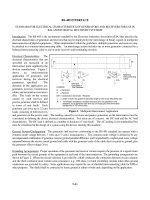
When is it necessary to modify the histogram of an image?
Suppose that we cannot see much detail in the image. The reason is most likely that
pixels which represent different objects or parts of objects tend to have grey level
values which are very similar to each other. This is demonstrated with the example
histograms shown in
Figure
4.1. The histogram of the “bad” image is very narrow,
while the histogram of the image is more spread.
number
of
pixels
number
of
pixels
grey
level
-
grey
level
Figure
4.1:
(a) is the histogram of a “bad” image while (b) is the histogram
of a “good” image.
How can we modify the histogram of an image?
Suppose that the grey levels in the original image are given by the values
a
variable
r
obtains and in the new image by the values
a
variable
s
obtains. We would like
to find
a
transformation
s
=
T(r)
such that the probability density function
pr(r)
in
Figure
4.la is transformed into
a
probability density function
p,(s)
which looks like
that in
Figure
4.lb, say.
Since
pr(r)
is the probability density function of random variable
T,
the number
of pixels with grey level values in the range
r
to
r
+
dr
is
pr(r)dr.
The transformation
we seek will transform this range to
[S,
s
+
ds].
The total number of pixels in this
range will remain the same but in the enhanced image this number will be
p,(s)ds:
ps(s)ds
=
pr(r)dr
(4.1)
Image Enhancement
127
This equation can be used to define the transformation
T
that must be applied to
variable
r
to obtain variable
S,
provided we define function
p,(s).
What is histogram equalization?
Histogram equalization is the process by which we make all grey values in an image
equally probable, i.e. we set
ps(s)
=
c,
where
c
is
a
constant. Transformation
S
=
T(r)
can be calculated from equation (4.1) by substitution of
p,(s)
and integration. We
integrate from
0
up to an arbitrary value of the corresponding variable, making use
of
the fact that equation (4.1) is valid for any range of values. These limits are equivalent
of saying that we equate the
distribution
functions of the two random variables
S
and
r:
Here, in order to avoid confusion we replaced the dummy variable of integration
by
z.
Figures
4.2a-4.2d show an example of applying this transformation to
a
low
contrast image. Notice how narrow the histogram 4.2b of the original image 4.2a
is. After histogram equalization, the histogram in 4.2d is much more spread, but
contrary to our expectations, it is not
flat,
i.e. it does not look “equalized”.
Why do histogram equalization programs usually not produce images with
flat histograms?
In the above analysis, we tacitly assumed that variables
r
and
S
can take continuous
values. In reality, of course, the grey level values are discrete. In the continuous
domain there is an infinite number of numbers in any interval
[r, r
+
dr].
In digital
images we have only
a
finite number of pixels in each range. As the range is stretched,
and the number of pixels in it is preserved, there is only this finite number of pixels
with which the stretched range is populated. The histogram that results is spread
over the whole range of grey values, but it is far from
flat.
Is it possible to enhance an image to have an absolutely flat histogram?
Yes, if we randomly re-distribute the pixels across neighbouring grey values. This
method is called histogram equalization with
random additions.
We can better follow
it if we consider
a
very simple example. Let
us
assume that we have
NI
pixels with
value
g1
and
NZ
pixels with value
g2.
Let
us
say that we wish to stretch this histogram
so
that we have
(NI
+
N2)/3
pixels with grey value
31,
(NI
+
N2)/3
pixels with grey
value
32
and
(NI
+
N2)/3
pixels with grey value
33.
Let
us
also assume that we
have worked out the transformation that leads from
gi
to &. After we apply this
transformation, we may find that we have
fi1
pixels with grey value
31,
fi2 pixels
with grey value
32,
fi3
pixels with grey value
33,
and that
fi1
>
(NI
+
N2)/3,
fi2
<
(NI
+
N2)/3
and
fi3
<
(NI
+
N2)/3.
We may pick
at
random
(NI
+
N2)/3
-
fi3
pixels
with value
32
and give them value
33.
Then we may pick
at
random
fi1-
(NI
+
N2)/3
128
Image Processing: The Fundamentals
4000
r
I:
1w
Gray
Levels
200
(a) Original image
(b)
Original histogram
(c)
After histogram
equalization
(e) After histogram
equalization with ran-
dom additions
(d) Histogram after histogram
equalization
0
L
,W
Gray
Levels
200
(f) Histogram after histogram
equalization with random addi-
tions
Figure
4.2:
Enhancing the image
of
a bathtub cleaner by histogram equal-
ization
Image Enhancement 129
(a)
After histogram hy-
(b)
Histogram after histogram
perbolisation
hyperboliaation
1w
200
Gray Levels
l
(c)
After histogram hy-
(d)
Histogram after histogram
perbolization with ran-
hyperbolization with random
dom
additions additions
Figure 4.3: Histogram hyperbolization with
a
=
0.5
applied to the image
of
Figure
4.2a
with value
31
and give them value
32.
The result will be
a
perfectly
flat
histogram.
An example of applying this method can be seen in
Figures
4.2e and 4.3~.
What if we do not wish to have an image with a flat histogram?
We may define
p,(s)
to be any function we wish. Then:
LSP"(")dY
=
/kz)dz
0
where in order to avoid confusion we have used
z
and
y
as the dummy variables
of
integration. This equation defines
S
directly in terms of
T.
Since
ps(y)
is known (the
desired histogram), one can solve the integral on the left hand side to find
a
function
130
Image Processing: The Fundamentals
f~
of
S.
Similarly, the integral on the right hand side can be performed to yield a
function
f2
of
r;
i.e.
fl(S)
=
f2(7-)
*
S
=
fL1f2(r)
(4.3)
In practice, one may define an intermediate transformation by:
W
E
i'Pr(x)dx
(4.4)
This transformation gives the values
W
of the equalized histogram of the given image.
Clearly:
I"
PdYPY
=
W
(4.5)
This defines another transformation such that
W
=
Tz(s)
while we actually need
S
in
terms of
W.
So
this is
a
three-step process:
1.
Equalize the histogram of the given image.
2. Specify the desired histogram and obtain the transformation
W
=
T~(s).
3.
Apply the inverse of the above transformation to the equalized histogram.
An example of applying this method to image 4.2a can be seen in
Figures
4.3a and
4.3b. This histogram has been produced by setting
p,(s)
=
ae-"'
where
Q!
is some
positive constant. The effect is to give more emphasis to low grey level values and
less to the high ones. This effect is barely visible in
Figure
4.3b because it is masked
by the discretization effect. However, in
Figure
4.3d it can be seen clearly because
the method of random additions was used.
Why should one wish to perform something other than histogram
equalization?
One may wish to emphasize certain grey values more than others, in order to com-
pensate for
a
certain effect; for example, to compensate for the way the human eye
responds to the different degrees of brightness. This is
a
reason for doing histogram
hyperbolization: it produces
a
more pleasing picture.
Example
4.1
The histogram of an image can be approximated by the probability
density function
p'(.)
=
Ae-'
where
r
is the grey-level variable taking values between
0
and
b,
and
A
is a normalizing factor. Calculate the transformation
S
=
T(r),
where
S
is the grey level value in the transformed image, such that the trans-
formed image has probability density function
Image Enhancement
131
p,(s)
=
Bse-"
where
S
takes values between
0
and
b,
and
B
is some normalizing factor.
The transformation
S
=
T(r)
can be calculated using equation
(4.1).
BsePs2ds
=
AeC'dr
We integrate both sides
of
this equation to obtain the relationship between the
distribution functions
of
variables
S
and
r.
To avoid confusion we use as dummy
variables
of
integration y on the left hand side and
X
on the
right
hand side:
B
ye-Y2dy
=
A
e-"dx
LT
The left hand side
of
(4.6) is:
The
right
hand side
of
(4.6) is:
We substitute from (4.7) and (4.8) into (4.6) to obtain:
1
-
e-s2
A
2
B
B
=
-(l
-
e-')
+
e-s2
- -
1
-
-(l
2A
-e-')
+
What if the image has inhomogeneous contrast?
The approach described above is global, i.e. we modify the histogram which refers
to the whole image. However, the image may have variable quality
at
various parts.
For example, it may have
a
wide shadow band right in the middle, with its top and
bottom parts being adequately visible. In that case we can apply the above techniques
locally: We
scan
the image with
a
window inside which we modify the histogram but
132
Image Processing: The Fundamentals
we alter only the value of the grey level of the central pixel. Clearly such a method
is costly and various algorithms have been devised to make it more efficient.
Figure
4.4a shows
a
classical example of an image that requires local enhancement.
The picture was taken indoors looking towards windows with plenty
of
ambient light
coming through. All outdoor sections are fine, but in the indoor part the film was
under-exposed. The result of global histogram equalization shown in
Figure
4.4b is
not bad, but it makes the outdoor parts over-exposed in order to allow
us
to see
the details of the interior. The result of the local histogram equalization on the other
hand, shown in
Figure
4.4c, is overall
a
much more balanced picture. The window size
used for this was 40
X
40, with the original image being of size 400
X
400. Notice that
no part of the picture gives the impression of being over-exposed or under-exposed.
There are parts of the image, however, that look damaged:
at
the bottom of the
picture and
a
little
at
the top. They correspond to parts of the original film which
received too little light to record anything. They correspond to flat black patches,
and by trying to enhance them we simply enhance the film grain or the instrument
noise. This effect is more prominent in the picture
of
the hanging train
of
Wupertal
shown in
Figure
4.5. Local histogram equalization (the result
of
which is shown in
Figure
4.5~) attempts to improve parts of the picture that are totally black, in effect
trying to amplify non-existing information. However, those parts
of
the image with
some information content are enhanced in
a
pleasing way.
A
totally different effect becomes evident in
Figure
4.6~ which shows the local
histogram enhancement of
a
picture taken
at
Karlstejn castle in the Czech Republic,
shown in
Figure
4.6a. The castle
at
the back consists
of
flat
grey walls. The process
of local histogram equalization amplifies every small variation
of
the wall to such a
degree that the wall looks like the rough surface of
a
rock. Further, on the left
of
the
picture we observe again the effect of trying to enhance a totally black area. In this
case, the result of global histogram equalization looks much more acceptable, in spite
of the fact that if we were to judge from the original image, we would have thought
that local histogram equalization would produce
a
better result.
Is there an alternative to histogram manipulation?
Yes, one may use the mean and standard deviation
of
the distribution of pixels inside
a
window. Let
us
say that the mean grey value inside a window centred
at
(X,
y)
is
m(z,
g),
the variance of the pixels inside the window is
O(X,
y),
and the value of pixel
(X,
y)
is
f
(X,
y).
We can enhance the variance inside each such window by using a
transformation of the form:
where
A
is some scalar.
So
we choose the amplification factor
A
inversely proportional to
O(X,
y):
We would like areas which have low variance to have their variance amplified most.
Image Enhancement
133
where
k
is
a
constant, and
M
is the average grey value
of
the image.
Figure
4.4d shows the results
of
applying this process to image 4.4a with
k
=
3
and window size 5
X
5. Note that although details in the image have become explicit,
the picture overall is too dark and not particularly pleasing.
Figures
4.5d and 4.6d
show the results
of
applying the same process to the images 4.5a and 4.6a respectively,
with the additional post-processing
of
histogram equalization.
U
(a)
Original image
(b)
After global histogram equalization
(c) After local histogram equalization
(d)
After local enhancement
Figure
4.4:
Enhancing the image
of
a young train driver.
134
Image Processing: The Fundamentals
c
l
.
.
(a) Original image
(b)
After global histogram equalization
(c) After local histogram equalization
(d)
After local enhancement
Figure
4.5:
Enhancing the image
of
the hanging train
of
Wupertal.
Image Enhancement
135
(a)
Original image
(b)
After global histogram equalization
(c) After local histogram equalization
(d)
After local enhancement
Figure
4.6:
Enhancing the image at the Karlstejn castle.
How can we improve the contrast
of
a multispectral image?
A
multispectral
or
multiband
or colour image consists
of
several arrays
of
the same
scene, one for each spectral component. Each of these bands is
a
grey level image
giving the intensity of light
at
the particular spectral component
at
the position of each
136
Image Processing: The Fundamentals
pixel. Suppose for simplicity that we have three spectral bands, Red, Green and Blue.
Then each picture consists of three bands, three grey level images. Alternatively, we
may say that each pixel carries three values, one for each spectral band. We can
plot these triplets in
a
3D
coordinate space, called RGB because we measure the grey
value of
a
pixel in each of the three bands along the three axes. The pixels of the
colour image plotted in this space form
a
cluster.
If
we were to use only one of these bands, we would like to choose the one that
shows the most detail; i.e. the one with the maximum contrast, the one in which the
values of the pixels are most spread.
It
is possible that the maximum spread of the values of the pixels is not along any
of the axes, but along another line (see
Figure
4.7a). To identify this line we must
perform
principal component analysis
or take the
Karhunen-Loeve transformation
of
the image.
B
R
/
0 0
e/.
B
G
>
R
/
Figure
4.7:
The pixels of a colour image form a cluster in the colour space.
The maximum spread of this cluster may be along a line not parallel with
any of the colour axes.
What is principal component analysis?
Principal component analysis (or Karhunen-Loeve transformation) identifies
a
linear
transformation of the coordinate system such that the three axes of the new coor-
dinate system coincide with the directions of the three largest spreads of the point
distribution. In this new set of axes the data are uncorrelated. This means that if
we form
a
grey image by using the values of the first co-ordinate of each pixel, it will
contain totally uncorrelated information from the information that will be contained
in the grey image formed by the second coordinate of each pixel and the information
contained in the image formed by the third coordinate of each pixel.
Image Enhancement
137
What is the relationship of the Karhunen-Loeve transformation discussed
here and the one discussed in Chapter
3?
They both analyse an ensemble of random outcomes into their uncorrelated compo-
nents. However, in Chapter
3
the whole image was considered as the outcome of
a
random experiment, with the other random outcomes in the ensemble not available.
Their lack of availability was compensated by the assumed ergodicity.
So,
although
the ensemble statistics were computed over the single available image using spatial
statistics, they were assumed to be averages computed over all random outcomes, i.e.
all versions of the image. Here the values of
a
single
pixel are considered to be the
outcomes of
a
random experiment and we have
at
our disposal the whole ensemble
of
random outcomes made up from all the image pixels.
How can we perform principal component analysis?
To perform principal component analysis we must diagonalize the covariance matrix
of our data. The autocovariance function of the outputs of the assumed random
experiment is:
C(i,j)
=
E(("i(h1)
-
"io)("j(k,l)
-
"jo))
where
zi(k,
1)
is the value of pixel
(k,
1)
at
band
i,
zio
is the mean of band
i,
xj
(k,
1)
is
the value of the same pixel in band
j,
xjo
is the mean of band
j,
and the expectation
value is over all outcomes of the random experiment, i.e. over all pixels of the image:
(4.10)
b=l
k1
Since we have three bands, variables
i
and
j
take only three values to indicate
R,G
and
B
and the covariance matrix is
a
3
X
3
matrix. For data that are uncorrelated,
C
is diagonal; i.e.
C(i,j)
=
0
for
i
#
j.
To achieve this we must transform our data
using the transformation matrix
A
made up from the eigenvectors of the covariance
matrix of the untransformed data. The process is as follows:
1.
Find the mean of the distribution of points in the colour space, say point
(Ro,
Go, Bo).
2.
Subtract the mean grey level value from each corresponding band. This is
equivalent to translating the
RGB
coordinate system to be centred
at
the centre
of the pixel distribution (see axes
R'G'B'
in
Figure
4.7b).
j
take the values
R,
G
and
B).
3.
Find the autocorrelation matrix
C(i,
j)
of the initial distribution (where
i
and
4. Find the eigenvalues of
C(i,
j)
and arrange them in
decreasing
order. Form
the eigenvector matrix
A,
having the eigenvectors as rows.
138
Image Processing: The Fundamentals
5.
Transform the distribution using matrix
A.
Each triplet
X
=
K)
is
trans-
formed into
y
=
(2)
by:
y
=
Ax;
i.e.
~k
=
xi
akixi.
p3
This is
a
linear transformation. The new “colours” are linear combinations of the
intensity values of the initial colours, arranged
so
that the first principal component
contains most of the information for the image (see
Figure
4.7b).
What are the advantages
of
using principal components to express an
image?
The advantages of using principal components are:
1.
The information conveyed by each band is maximal for the number of bits used
because the bands are uncorrelated and no information contained in one band
can be predicted by the knowledge of the other bands.
2.
If
we want to use
a
monochrome version of the image, we can restrict ourselves
to the first principal component only and be sure that it has the maximum
contrast and contains the maximum possible information conveyed by
a
single
band of the image.
An example of principal component analysis is shown in
Figure
4.8. Although
at
first glance not much difference is observed between
Figures
4.8a, 4.8b, 4.8~ and
4.8d,
at a
more careful examination, we can see that the first principal component
combines the best parts of all three bands: For example, the face of the boy has more
contrast in 4.8b and 4.8~ than in 4.8a, while his right leg has more contrast with his
trousers in 4.8a and 4.8b than in 4.8~. In 4.8d we have good contrast in both these
places. Similarly, the contrast between the trousers and the ground is non-existent in
4.8a and 4.8b but it is obvious in 4.8~. Image 4.8d shows it as well.
What are the disadvantages
of
principal component analysis?
The grey values in the bands created from principal component analysis have no
physical meaning, as they do not correspond to any physical colours.
As
a
result, the
grey value of
a
pixel cannot be used for the classification of
a
pixel. This is particularly
relevant to remote sensing applications, where often pixels are classified according to
their grey values. In
a
principal component band,
pixels that represent water, for
example, may appear darker or brighter than other pixels in the image depending on
the image content, while the degree of greyness of water pixels in the various
spectral
bands
is always consistent, well understood by remote sensing scientists, and often
used to identify them.
Image Enhancement
139
(a)
Red component
(b)
Green component (c) Blue component
(d) First principal corn- (e) Second principal com-
(f)
Third principal com-
ponent ponent ponent
Figure
4.8:
Example
of
principal component analysis of a colour image.
Example
4.2
Is it possible
for
matrix
C
below to represent the autocovariance matrix
of
a three-band image?
-1
0
This matrix cannot represent the autocovariance matrix
of
an image because from
equation
(4.10)
it
is obvious that
C
must be symmetric with positive elements
along its diagonal.
141
The transformation matrix
A
is:
-_
__
Example
4.4
A
4
X
4
three-band image is given:
3356 3234 4234
R=
(3
4556
')
G=('
4536
')
B=('
4335
')
4556 2445 2355
Calculate its three principal components and verify that they are
uncorrelated.
First we calculate the mean
of
each band:
1
16
R0
=
-(3+3+5+6+3+4+4+5+4+5+5+6+4+5+5+6)
73
16
-
-
-
=
4.5625
Go
=
-(3+2+3+4+1+5+3+6+4+5+3+6+2+4+4+5)
1
16
60
16
-
-
-
=
3.75
B0
=
-(4+2+3+4+1+4+2+4+4+3+3+5+2+3+5+5)
1
16
-
50
-
-
16
=
3.375
Next we calculate the elements
of
the covariance matrix as:
142
Image Processing: The Fundamentals
.44
CGG
=
-
C
C
(G(k,
1)
-
Go)2
=
1.9375
l
16
k=l1=1
-44
I"
k=l1=1
Therefore, the covariance matrix is:
0.996094
0.953125
0.726563
0.953125
1.937500 1.281250
0.726563
1.28125 1.359375
The eigenvalues
of
this matrix are:
X1
=
3.528765
X2
=
0.435504
X3
=
0.328700
The corresponding eigenvectors are:
0.427670
0.876742
0.220050
0.561576
-0.448457
0.695355
u1
=
(0.708330)
uz
=
(
-0.173808)
u3
=
(
-0.684149
)
The transformation matrix therefore is:
0.427670
0.708330
0.561576
A=
(
0.876742
-0.173808
-0.448457
0.220050 -0.684149 0.695355
We can find the principal components
by
using this matrix to transform the values
of
every pixel. For example,
for
the first few pixels we find:
0.427670
0.708330
0.561576
)
(i)
0.876742
-0.173808 -0.448457
0.220050
-0.684149 0.695355
Image Enhancement
143
0.427670
0.708330
0.561576
)
(f)
0.876742
-0.173808
-0.448457
0.220050
-0.684149
0.695355
0.427670
0.708330
0.561576)
(,5)
0.876742
-0.173808
-0.448457
0.220050
-0.684149
0.695355
We use the first element of each transformed triplet to form the first principal
component of the image, the second element for the second principal component,
and the third for the
third
one.
In
this way we derive:
5.654302 3.822820
5.948065
7.645640
2.552915 7.498631
4.958820
8.634631
6.790301 7.364725
5.948065
9.623876
4.250490 6.656395
7.779546
8.915546
0.314974
1.385694 2.516912
2.771389
2.007960 0.844099
2.088630
1.547035
1.017905
2.169300 2.516912
1.975317
2.262436
2.343106 1.446188
2.149123
p1=
(
p2=
(
1.389125 0.682562 1.133874 1.365131
0.925027 -0.234424 1.133874 0.692187
0.902617 0.449725 1.840433 1.376336
0.671360 0.240878 0.218468 -0.223219
TO
confirm that these new bands contain uncorrelated data we shall calculate their
autocovariance matrix. First we
find
the mean
of
each band:
P~o, Pm, P30.
Then
we compute:
1
44
Cplpl
=
-
F,y,
(PI(i,j)
-
P10)2
=
3.528765
l6
i=l
j=1
-44
144
Image Processing: The Fundamentals
1
16
. .
44
Cp3p3
=
-
(P3(i,j)
-
P~o)~
=
0.328700
2=13=1
We see that this covariance matrix is diagonal,
so
it
refers to uncorrelated data.
Example
4.5
For
the image in Example
4.4
show that the first principal component
has more contrast than any
of
the original bands.
The contrast
of
an image can be characterized by the range
of
grey values
it
has.
We can see that the contrast
of
the original image was
3
in
the red band,
5
in
the green band and
4
in
the blue band. The range
of
values
in
the first principal
component is
9.623876
-
2.552915
=
7.070961.
This is larger than any
of
the
previous ranges.
Some
of
the images with enhanced contrast appear very noisy. Can we do
anything about that?
Indeed, this is the case for images 4.4c, 4.5~ and 4.6c, where there are large uniformly
coloured regions, which happen to cover entirely the window inside which local his-
togram equalization takes place. Then the grey values of these pixels are stretched
to the full range of 0-255, and the noise is significantly enhanced. We have to use
then some noise reduction techniques to post-process the image. The technique we
use depends on the type of noise that is present in the image.
What are the types
of
noise present in an image?
There are various types of noise. However, they fall into two major classes:
additive
and
multiplicative
noise. An example of multiplicative noise is variable illumination.
This is perhaps the most common type of noise in images. Additive noise is often
assumed to be
impulse noise
or
Gaussian noise. Figure
4.9a shows an image corrupted
with impulse noise and
Figure
4.9b shows an image corrupted with additive zero-mean
Gaussian noise.
Impulse noise alters
at
random the value of some pixels. In a binary image this
means that some black pixels become white and some white pixels become black.
This is why this noise is also called
salt and pepper noise.
Additive zero-mean Gaus-
sian noise means that
a
value drawn from
a
zero-mean Gaussian probability density
function is added to the true value of every pixel.
Image Enhancement
145
(a) Image with impulse noise
(b)
Image with additive Gaussian noise
(c)
Median filtering
of
(a) (d) Median filtering
of
(b)
Q
!
’
-J ;
’
L-
c,
(e) Smoothing
of
(a)
by
averaging
(f)
Smoothing
of
(b) by
averaging
Figure
4.9:
Examples
of
filtering to remove noise.
146
Image Processing: The Fundamentals
We use
rank order filtering
to remove impulse noise and
smoothing
to reduce
Gaussian noise.
What is a rank order filter?
A
rank order filter is
a
filter the output value of which depends on the ranking
of
the
pixels according to their grey values inside the filter window. The most common rank
order filter is the
median filter.
Figure
4.10 shows the result
of
trying to remove the noise from output images 4.4~
and 4.5~ by median filtering.
?
T
I'
tB
Figure
4.10:
Improving images
4.4~
and
4.5~
by
using median filtering
(median filter size
=
3
X
3).
What is median filtering?
The median is the grey level value which divides
a
distribution in two equally num-
bered populations. For example, if we use
a
5
X
5 window, we have 25 grey level
values which we order in an increasing sequence. Then the median is the thirteenth
value. This has the effect
of
forcing points with distinct intensities to be more like
their neighbours, thus eliminating intensity spikes which appear isolated.
Figure
4.9~ shows image 4.9a processed with
a
median filter and with a window of
size 5
X
5, while
Figure
4.9d shows image 4.9b (which contains Gaussian noise) having
been processed in the same way.
It
is clear that the median filter removes the impulse
noise almost completely.
Image Enhancement 147
What if the noise in an image
is
not impulse?
The most common type of noise in images is Gaussian. We can remove Gaussian
noise by
smoothing
the image. For example, we may replace the value of each pixel
by the average value inside
a
small window around the pixel.
Figures
4.9e and 4.9f
show the result of applying this process to images 4.9a and 4.9b respectively. The
size of the window used is the same as for the median filtering of the same images,
i.e.
5
X
5.
We note that this type of filtering is much more effective for the Gaussian
noise, but produces bad results in the case of impulse noise. This is
a
simple form of
lowpass
filtering
of the image.
Why does lowpass filtering reduce noise?
Usually, the noise which is superimposed on the image is uncorrelated. This means
that it has
a flat
spectrum. On the other hand, most images have spectra which have
higher values in the low frequencies and gradually reducing values for high frequencies.
After
a
certain frequency, the spectrum of
a
noisy signal is dominated by the noise
component (see
Figure
4.11).
So,
if we use
a
lowpass filter, we kill off all the noise-
dominated high-frequency components. At the same time, of course, we kill also the
useful information of the image buried in these high frequencies. The result is
a
clean,
but blurred image. The process is as follows:
1. Find the Fourier transform of the image.
2. Multiply it with
a
function which does not alter frequencies below
a
certain
cutoff frequency but which kills off all higher frequencies. In the 2-dimensional
frequency space, this ideal lowpass filter is schematically depicted in
Figure
4.12.
3.
Take the inverse Fourier transform of this product.
Spectral Clean image spectrum
magnitude
/Noise spectrum
-
r
Figure 4.11: After a certain frequency, the spectrum of the noisy image
is
dominated by the noise. Ideally the cutoff frequency of the lowpass filter
should be at
TO
=
F.
148 Image Processing: The Fundamentals
Multiplication of the two frequency spectra is equivalent to convolution
of
the actual
functions.
So,
what we can do instead of the above procedure, is to find the
2-
dimensional function in real space which has as its Fourier transform the ideal lowpass
filter, and convolve our image with that function. This would be ideal, but it does
not work in practice because the function the Fourier transform
of
which is the ideal
lowpass filter is infinite in extent.
I
H(Wx
1
Y
‘0
r
Figure 4.12: The ideal lowpass filter in 2D in the frequency domain. On the
right a cross-section of this filter with cutoff frequency
TO
(r
=
What if we are interested in the high frequencies of an image?
It
is possible that we may want to enhance the small details of
a
picture instead
of
ironing them out. Such
a
process is called
sharpening
and it enhances small fluctua-
tions in the intensity of the image, noise included.
One way to achieve this is to calculate
at
each pixel the local gradient of the
intensity using numerical difference formulae.
If
one wants to be more sophisticated,
one can use the filtering approach we discussed in the context of smoothing. Only
now, of course, the filter should be highpass and allow the high-frequency components
to survive while killing the low-frequency components.
What
is
the ideal highpass filter?
The ideal highpass filter in the frequency domain is schematically depicted in
Figure
4.13.
Filtering with such
a
filter in the frequency domain is equivalent to convolving
in real space with the function that has this filter as its Fourier transform. There is
no finite function which corresponds to the highpass filter and one has to resort to
various approximations.
Image Enhancement
149
‘0
r
Figure
4.13:
The spectrum of the ideal highpass filter
is
1
everywhere,
except inside a circle of radius
TO
in the frequency domain, where it is
0.
On the right, a cross-section of such a filter. Here
T
E
How can we improve an image which suffers from variable illumination?
This is
a
problem which can be dealt with if we realize that every image function
f(z,
y)
is the product of two factors: an illumination function
i(z,
y)
and
a
reflectance
function
r(z,
y)
that is intrinsic to the imaged surface:
Illumination is generally of uniform nature and yields low-frequency components
in the Fourier transform of the image. Different materials (objects) on the other
hand, imaged next to each other, cause sharp changes of the reflectance function,
which causes sharp transitions in the intensity of an image. These sharp changes are
associated with high-frequency components. We can try to separate these two factors
by first taking the logarithm of equation (4.11)
so
that the two effects are additive
rather than multiplicative: In
f(z,
y)
=
In
i(z,
y)
+
In
~(z,
y)
Then we filter this logarithmic image by what is called
a
homomorphic
filter.
Such
a
filter will enhance the high frequencies and suppress the low frequencies
so
that the variation in the illumination will be reduced while edges (and details) will
be sharpened. The cross-section of
a
homomorphic filter looks like the one shown in
Figure
4.14.
Figures
4.15a and 4.16a show two images with smoothly varying illumination from
left to right. The results after homomorphic filtering shown in
Figures
4.15b and 4.16b
constitute
a
clear improvement with the effect of variable illumination greatly reduced
and several details particularly in the darker parts of the images made visible. These
results were obtained by applying to the logarithm of the original image,
a
filter with
the following transfer function: