Tài liệu Diezel 1410 P4
Bạn đang xem bản rút gọn của tài liệu. Xem và tải ngay bản đầy đủ của tài liệu tại đây (423.35 KB, 11 trang )
4
ENGINE AIR STARTING SYSTEMS
A. GENERAL
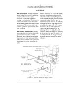
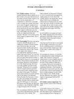
4A1. Description. Modern submarine
diesel engines are started by admitting
compressed air into the engine
cylinders at a pressure capable of
turning over the engine. This process is
continued until the pistons have built
up sufficient compression heat to cause
combustion. The pressure used in air
starting systems is approximately from
250 to 500 psi.
4A2. Source of starting air. Starting
air comes directly from the ship's high-
pressure air service line in which
pressures up to 3,000 psi are normally
maintained, or from starting air flasks
which are included in some systems for
the purpose of storing starting air. In
either
instance, the air on the way to the engine,
must pass through a pressure reducing
valve which reduces the higher pressure
to the operating pressure required to start
a particular engine. A relief valve is
installed in the line between the reducing
valve and the engine. This relief valve is
normally set to open at 25 to 50 pounds
in excess of the air starting pressure.
Thus, if the air pressure leaving the
reducing valve is too high, the relief
valve will protect the engine by releasing
air in excess of the value for which it is
set and permit only air at approximately
the proper pressure to reach the engine
cylinders.
Figure 4-1. Typical starting air piping system.
81
Figure 4-2. Grove regulator valve.
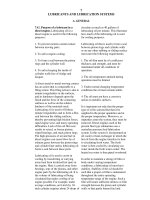
4A3. Pressure regulating valve. The
pressure reducing valve is a Grove
regulator (Figure 4-2) in which
compressed air, sealed in a dome,
furnishes the regulating pressure that
actuates the valve. Thus the
compressed air in the dome performs
the same function as a spring used in a
conventional type of valve.
The dome is tightly secured to the valve
body which is separated into an upper
(low pressure outlet) and a lower (high-
pressure inlet ) chamber by the main
valve. At the top of the valve stem is
another chamber which contains a
rubber diaphragm and a metal
diaphragm plate. This chamber has an
opening leading to the low-pressure
outlet chamber. When the outlet
pressure drops below the pressure in
the dome, air in the dome forces the
diaphragm and the diaphragm plate
down on the valve stein. This opens the
valve and permits high-pressure air to
pass the valve seat into the low-
pressure outlet and into the space under
the diaphragm. As soon as the pressure
under the diaphragm is equal to that in
the dome, the diaphragm returns to its
normal
position and the valve is forced shut by
the high-pressure air acting on the valve
head. When air is being used from the
low-pressure side of the regulator, this
action is continuous and very rapid in
order to maintain the correct pressure on
the discharge side.
High-pressure air entering the valve body
is filtered through a screen to prevent the
entrance of any particles of dirt which
would prevent the valve from seating
properly. The screen is held in position
around the space under the valve head
by
the threaded valve seat bushing. The
screen should be removed and cleaned
periodically to insure an unrestricted
flow of air, If particles of dirt are
permitted to remain and accumulate in
the screen, the high air pressure may tear
the screen from its position and force it
into the working parts, causing damage
to the valve seat.
Air for the original charging of the dome
is obtained from the high-pressure
chamber of the valve body by opening
two needle valves, As soon as the desired
pressure, as indicated by the gage on the
discharge side of the regulator,
82
Fi
gure 4-3. Engine starting control levers, GM.
is reached, the needle valves must be
closed. The dome will then regulate and
maintain the discharge of air at that
pressure.
4A4. Starting the GM engine. The
GM engine is started by means of two
control levers, the throttle hand lever
and the air starter hand valve lever. The
throttle hand lever has three positions,
STOP, START, and RUN. In the
STOP, or central, position, the fuel
supply to the cylinders is cut off.
Moving the lever toward the START
position rotates the fuel pump plunger
toward the full pump position. The
RUN position gives the Woodward
regulating governor unrestricted control
of the engine. The air starter hand valve
lever has only two positions, OPEN and
CLOSED.
Prior to starting the engine, and with
the throttle hand lever on the STOP
position, the engine is turned over
several times by opening the air starter
hand valve with the cylinder test valves
open. This insures that there are no
obstructions to prevent the starting of
the engine.
The cylinder test valves are then closed.
The engine is started by holding the
throttle hand lever in the START position
and opening the air starter hand valve.
The engine should start after a few
revolutions if the fuel supply has been
primed and is not airbound. As soon as
the engine is firing, the air starter hand
valve is closed and the speed of the
engine adjusted by means of the throttle
hand lever. As soon as the governor oil
pump has built up a working pressure,
the throttle lever is shifted to the RUN
position. This shifts the engine to
governor control.
4A5. Starting the F-M engine. The F-M
engine is started by means of a control
shaft lever. This lever has three positions,
START, STOP, and RUN. In the STOP
position, the fuel cutout cam on the
control shaft moves the fuel injection
pump control rod to the no fuel position.
When the lever is in the START position,
the air start control valve is opened,
allowing air starting of the engine. In the
RUN position, the engine is under full
governor control.
83
To start the engine, the governor is set
at idling speed and the control shaft
lever moved from the STOP position to
the RUN position and then toward the
START position. When the lever
lever reaches the START position, air
starting air begins to enter the cylinders.
As soon as the engine is firing, the
control shaft lever should be shifted to
RUN. This allows full governor control
passes the RUN position, the fuel
injection pump control rod is unlocked.
When the
and closes the air start control valve.
B. GENERAL MOTORS ENGINE AIR STARTING SYSTEM
4B1. Description. The engine air
starting system used on GM engines is
known as the separate distributor type,
the starting air distributor valve being a
separate unit for each cylinder. Each
distributor valve is individually
operated by its cam on the camshaft.
Eight of the 16 cylinders, six in one
bank and two in the other, are air
started, but all of the cylinder heads in
both banks are equipped with air starter
check valves so as to maintain full
interchangeability. On the cylinders
that are not air started, the air inlet
opening is sealed with a removable
plug.
4B2. Operation. Air is supplied to the
air starting hand control valve from the
air supply line. The air starting control
valve is opened by a hand lever,
thereby admitting air to the starting air
manifold. The starting air manifold is a
steel pipe extending the full length of
the engine and is located on the top
deck of the engine below the exhaust
manifold. It is connected by air lines to
each of the starting air distributor
valves. The distributor valves are
opened in engine cylinder firing order
by their cams on the camshafts,
admitting air into the lines that connect
each distributor valve to its air starting
check valve. As the distributor valve
admits air into the line leading to the air
starting check valve, the pressure opens
the check valve, thereby admitting air
into the combustion chamber;
The air pressure moves the pistons and
turns the crankshaft until there is
sufficient compression for combustion.
Combustion pressure and exhaust gases
are kept from backing into the air
starting system by the check valves. As
soon as the engine is firing, the hand
lever is released, and spring pressure
closes the air starting control valve.
This shuts off the supply of starting air
bracket bolted to the camshaft drive
cover near the hand control lever. It is a
poppet type valve, opened manually by a
lever and closed by a spring. A plug in
the valve body holds the spring against
the valve head. The valve stem guide is a
bronze bushing pressed into the body. A
spring and head placed over the valve
stem, where it projects from the body,
return the hand lever to the valve's closed
position. The hand lever and the
operating lever stop are keyed to a shaft
in the bracket.
A safety device prevents opening of the
air starting control valve while the engine
jacking gear is engaged.
4B4. Air starting distributor valve.
Each
Figure 4-4. Control shaft lever, F-M.
to the engine.
4B3. Air starting hand control valve.
The air starting hand control valve is
mounted on a
84
Figure 4-5. GM engine air starting system.
85
cylinder having air starting is equipped
with an air starting distributor valve.
The air starting distributor valves, or
timing valves as they are sometimes
called, are of the poppet type with
forged steel bodies that bolt to the
camshaft intermediate covers. The
valve is held closed by spring pressure
bearing against the top of the valve and
is guided in the hollow end of a cam
follower which rides on the camshaft
in the cylinder head. The valve body fits
into a recess in the cylinder head and is
held in place by a cap nut that screws
into the cylinder head and ears on the top
of the valve body. The valve body
contains the valve seat and serves as a
valve stem guide. Air is prevented from
leaking to the outside of the valve body
by a synthetic rubber seal ring located
above the inlet port. The valve face
makes direct contact with the valve seat
in the valve body. The valve is held