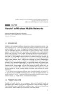
Tài liệu Sổ tay RFID (P12) ppt
Bạn đang xem bản rút gọn của tài liệu. Xem và tải ngay bản đầy đủ của tài liệu tại đây (528.58 KB, 11 trang )
12
The Manufacture
of Transponders and
Contactless Smart Cards
12.1 Glass and Plastic Transponders
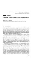
A transponder is made up of two components: the electronic data carrier and the
housing. Figure 12.1 gives a simplified representation of the manufacturing process
for an inductively coupled transponder.
12.1.1 Module manufacture
In accordance with the normal semiconductor manufacturing procedure, the microchip
is produced on a so-called wafer . This is a slice of silicon, which may be 6 inches
in diameter, upon which several hundred microchips are produced simultaneously by
repeated doping, exposure, etching and washing of the surface.
In the next stage of production, the microchips on the wafer are contacted using
metal points and then each of the chips is individually tested for functionality. The
chips have additional contact fields for this purpose, which give direct access — i.e.
without going through the HF interface — to the chip’s memory and security electron-
ics. The chips are placed in so-called test mode during this procedure, which permits
unlimited direct access to all functional groups upon the chip. The functional test can
therefore be performed significantly more intensively and comprehensively than would
be possible later on, when communication can only taken place via the contactless
technology.
All defective chips are marked with a red ink dot at this stage, so that they can
be identified and separated out in the subsequent stages of production. The test mode
can also be used to programme a unique serial number into the chip, if the chip has
an EEPROM. In read-only transponders, the serial number is programmed by c utting
through predefined connecting lines on the chip using a laser beam.
After the successful completion of the test programme the test mode is deactivated
by permanently breaking certain connections (so-called fuses) on the chip by a strong
RFID Handbook: Fundamentals and Applications in Contactless Smart Cards and Identification,
Second Edition
Klaus Finkenzeller
Copyright
2003 John Wiley & Sons, Ltd.
ISBN: 0-470-84402-7
330 12 THE MANUFACTURE OF TRANSPONDERS AND CONTACTLESS SMART CARDS
Wafer production
Manufacturing the
transponder coil
Module manufacture
Semi-finished transponder
Completion
Serial number programming
Electrical function test
Wafer sawing
Affixing in modules
Fitting into housing
Practical use
Initialisation
Electrical test
Coil contacting
Data
Figure 12.1 Transponder manufacture
current surge. This stage is important to prevent unauthorised reading of data at a later
date by the manipulation of the test contacts on the chip.
After the chips have been tested the wafer is sawn up using a diamond saw to give
individual transponder chips. A single chip in this state is known as a die (plural: dice).
A plastic foil is attached to the reverse of the wafer prior to the sawing operation to
prevent the dice from disintegrating (saw on foil).
After the sawing operation the dice can be removed from the plastic foil individually
and fitted into a module. The connection to the contact surfaces of the module for the
transponder coil is by bonding onto the reverse of the connection surfaces. Finally, the
dice are extrusion coated with a moulding substance. This significantly increases the
stability of the brittle and extremely breakable silicon dice. Very small dice, such as
those for read-only transponders (area of die: 1–2 mm
2
) are not fitted into a module
for reasons of space and cost. See Figure 12.2.
12.1.2 Semi-finished transponder
In the next stage, the transponder coil is produced using an automatic winding machine.
The copper wire used is given a coating of low-melting point baked enamel in addition
12.1 GLASS AND PLASTIC TRANSPONDERS 331
Figure 12.2 Size comparison of a sawn die with a cereal
grain. The size o f a transponder chip varies between 1 mm
2
and 15 mm
2
depending upon its function (photo: HITAG
Multimode-Chip, reproduced by permission of Philips Elec-
tronics N.V.)
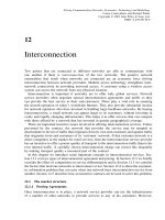
Figure 12.3 Manufacture of plastic transponders. In the figure an endless belt is fitted with
transponder coils wound onto a ferrite core. After the transponder chip has been fitted and
contacted, the transponder on the belt is sprayed with plastic (reproduced by permission of
AmaTech GmbH & Co. KG, Pfronten)
to the normal insulating paint. The winding tool is heated to the melting point of
the baked enamel during the winding operation. The enamel melts during winding
and hardens rapidly when the coil has been removed from the winding tool, causing
the individual windings of the transponder coil to stick together. This guarantees the
mechanical stability of the transponder coil during the following stages of assembly.
See Figure 12.3.
332 12 THE MANUFACTURE OF TRANSPONDERS AND CONTACTLESS SMART CARDS
Immediately after the winding of the transponder coil, the coil connections are
welded to the contact surface of the transponder module using a spot welding machine.
The shape and size of the transponder coil are determined by the format of the finished
transponder.
In dice that are not immediately fitted into a module, the copper wire can be bonded
directly to the die using a suitable procedure. However, this requires that the wire of
the transponder coil is as thin as possible. For this reason, the transponder coil of a
glass transponder is wound from wire that is only 30 µmthick.
Once the transponder coil has been contacted, the transponder is electrically func-
tional. Therefore a contactle ss functional test is carried out at this stage to sort out
those transponders that have been damaged during preceding stages. Transponders that
have not yet been fitted into housings are called semi-finished transponders, as they
can go from this stage into different housing formats.
12.1.3 Completion
In the next stage, the semi-finished transponder is inserted into a housing. This may
take place by injection moulding (e.g. in ABS), casting, pasting up, insertion in a glass
cylinder, or other procedures.
After a further functional test, the application data and/or application key can be
loaded into the transponder, if required.
12.2 Contactless Smart Cards
Contactless smart cards represent a very common special type of transponder. DIN/ISO
7810 specifies the format for all ID and smart cards. The dimensions of a smart
card are specified as 85.46 mm × 53.92 mm × 0.76 mm (± tolerances). The required
thickness of just 0.76 mm represents a par ticular challenge for the manufacture of
contactless smart cards because this places strict limits on the possible dimensions of
the transponder coil and chip module.
A contactless smart card may, for example, be manufactured from four PVC foils
of around 0.2 mm thickness: two inlet foils that are inserted in the inside of the card
and two overlay foils that will form the outside of the card. Contactless smart cards are
produced in sheets of 21, 24 or 48. The foils used thus have an area of around 0.1 to
0.3 m
2
. The typical foil structure of a contactless smart card is shown in Figure 12.4.
The two overlay foils are printed with the layout of the smart card. On modern printing
machines a high-quality coloured print is possible, such as that familiar from telephone
smart cards.
The antenna in the form of a coil is applied to one of the two inlet foils, the carrier
foil, and connected to the chip module using a suitable connection technique. Four
main procedures are used for the manufacture of the antenna coil: winding, embedding,
screen printing and etching.
The carrier foil is covered by a second inlet foil, from which the area of the chip
module has been stamped out. Often a fi ller is also dosed into the remaining hollow
space. This filling is necessary to prevent the overlay foils applied after the lamination
12.2 CONTACTLESS SMART CARDS 333
Filling
Overlay foil
Stamped out foil
Connection
method
Antenna
Carrier foil
Overlay foil
Contactless
chip module
Figure 12.4 Foil structure of a contactless smart card
process (see Section 12.2.3) from collapsing around the chip module and to give a
smooth and even card surface (Haghiri and Tarantino, 1999).
12.2.1 Coil manufacture
Winding
In the winding technique the transponder coil is wound upon a winding
tool in the normal way and affixed using baked enamel. After the chip module has been
welded onto the antenna, the semi-finished transponder is placed on the inlet sheet and
mechanically affixed using cemented joints (Figure 12.5).
For contactless smart cards in the frequency range <135 kHz the winding technique
is the only procedure that can be used for the manufacture of transponder coils due to
the high number of windings (typically 50–1500 windings).
Embedding
Inlet manufacture using the embedding technique (Figures 12.6 and 12.7)
is a relatively new procedure that is nevertheless increasing significantly in importance.
In this technique, the chip module is first affixed in its intended location on a PVC
foil. The wire is then embedded directly into the foil using a sonotrode. The sonotrode
consists of an ultrasonic emitter with a passage in its head through which the wire is
guided onto the foil. The ultrasound emitter is used to locally heat the wire to such a
degree that it melts into the foil and is thus fixed in shape and position. The sonotrode
is moved across the inlet foil in a similar manner to an X–Y plotter, while the wire
is fed through, so that the transponder can be ‘drawn’ or embedded. At the start and
the end of the coil a spot welding machine is used to make the electrical connection
to the transponder module.
Screen printing
The screen printing technique is a common printing technique in
industrial production and is used, for example, in the production of wallpaper, (PVC)
stickers, signs, and also in textile printing. A screen mesh made of synthetic or natural
fibres or metal wires is stretched over a frame. The fineness of the screen mesh and
the strength of the fibres are selected on the basis of the resolution of the print and
the viscosity of the paint. The template is applied to the screen mesh manually or
photomechanically. The actual print motif, in our case a coil, remains free. The template
material may, for example, be a light-sensitive emulsion that is applied to the screen.
If this coated screen is illuminated through a printing film, the emulsion hardens at
the illuminated points. The points that have not been illuminated are washed out with
water. Colour drawn over the screen with a rubber squeegee is pressed through these
334 12 THE MANUFACTURE OF TRANSPONDERS AND CONTACTLESS SMART CARDS
AmaTech
AmaTech coil winding principle
with interconnection
of coil wire ends with IC Module
Coil winding tool
Inlet sheet
DF / 18.Nov.1996
Heat & Force
LF & HF wound coil
Figure 12.5 Production of a semi-finished transponder by winding and placing the semi-
finished transponder on an inlet sheet (reproduced by permission of AmaTech GmbH & Co.
KG, Pfronten)
open points and onto the chosen material. The screen is raised and the print is complete.
All structures have a raster pattern due to the screen mesh. The elasticity of the screen
guarantees extremely high accuracy.
This procedure is used to print a coil of any shape directly onto an inlet foil
(Figure 12.8). So-called polymer thick film pastes (PTF) are used as the ‘printing ink’.
These consist of the powder of a conductive material (silver, copper, graphite), a light
solvent, and a resin as the fixing agent. After drying out, a conductive film is left
behind in the printed shape on the inlet. The surface resistance R
A
1
of the film is
around 5–100 /
1
and falls back to around 50–80% after lamination, since the
1
The surface resistance R
A
of a quadratic conductive layer is dependent only upon the specific conductivity
κ and the thickness d of the conductive layer and is quoted in /: R
A
=
1
κ · d
=
ρ
d
To determine the conductive track resistance, the surface resistance is multiplied by the ratio of length
l to breadth b of the conductive track: R = R
A
·
l
b
12.2 CONTACTLESS SMART CARDS 335
AmaTech
Z
X
Y
AmaTech wire embedding principle
with interconnection of coil wire ends with IC module
Sonotrode
HF embedded coil
Chip module
Inlet sheet
DF / 18.Nov.1996
Figure 12.6 Manufacture of an inlet sheet using the embedding principle (reproduced by per-
mission of AmaTech GmbH & Co. KG, Pfronten)
effect of heat and pressure during the lamination process increases the partial contact
between the individual grains of the mixed (metal) powder.
Depending upon layer thickness, conductor track width, and number of windings, a
typical coil resistance of 2–75 (smart card with 2–7 windings) can be achieved. Due
to the broad conductor track path (i.e. limited number of windings) this technology
is, however, only suitable for frequency ranges above 8 MHz. Due to cost benefits,
printed coils are also used for EAS tags (8 MHz) and Smart Labels (13.56 MHz).
Etching
The etching technique is the standard procedure used in the electrical industry
for the manufacture of printed circuit boards. Inlet foils for contactless smart cards can
also be manufactured using this procedure. In a special procedure a full-sized copper
foil of 35 µmto70µm thickness is first laminated onto a plastic foil without the use
of adhesive. This copper layer is now coated with a light-sensitive photo-resist, which
is dried and then illuminated through a positive film. The picture on the positive film
is the subsequent form of the coil. In a chemical developing solution the illuminated
points of the photo-resist are washed out, so that copper is once again exposed at these
points. In the subsequent etching bath, all areas that are no longer covered by photo-
resist are etched free of copper, so that fina lly only the desired coil form remains. The
336 12 THE MANUFACTURE OF TRANSPONDERS AND CONTACTLESS SMART CARDS
Figure 12.7 Manufacture of a smart card coil using the embedding technique on an inlet foil.
The sonotrodes, the welding electrodes (to the left of the sonotrodes) for contacting the coils,
and some finished transponder coils are visible (reproduced by permission of AmaTech GmbH
& Co. KG, Pfronten)
Figure 12.8 Example of a 13.56 MHz smart card coil using screen printing technology
coil resistance of an etched coil can easily be calculated from the surface resistance
R
A
(Cu: 500 µ/ where d = 35 µm).
12.2.2 Connection technique
The different types of antenna also require a different connection technique between
the antenna coil and the transponder chip.
12.2 CONTACTLESS SMART CARDS 337
Table 12.1 Surface resistance of polymer thick
film pastes with different admixtures given a layer
thickness of 25 µm (Anderson, 1998)
Conductor Surface resistance
Silver (Ag) 5–20 m/
Copper (Cu) 30–120 m/
Graphite (carbon) 20 000–100 000 m/
Table 12.2 Typical properties of some polymer thick film pastes (Anderson, 1998)
Paste Dupont 5028 Dupont 5029
Surface resistance after drying 27–33 m/ 14–20 m/
Surface resistance after lamination 8–10 m/ 4–5 m/
Layer thickness after drying (200 µm screen) 16–20 m/ 28–32 µm
Viscosity (RVT UC&S 14 10 rpm) 15–30 m/ 35–50 Pa.s
Antenna coils made of wire, i.e. wound or embedded coils, are connected to the chip
module using microwelding techniques. The lacquer enamelled antenna coil is bared in
the connection area of the chip module using a special tool and then welded to the termi-
nals (lead frames) of the chip module using ultrasound (Haghiri and Tarantino, 1999).
Contacting a printed coil to the chip or a module is problematic as conventional
soldering and welding techniques do not work for polymer pastes. The use of flip
chip technology,
2
in which fixing and contacting of the chip can take place using a
conductive adhesive, offers a solution. A second solution is the use of cut clamp tech-
nology (CCT). In this approach the metal terminals (lead frame) of the chip module are
punched through with a pointed tool, so that pointed crowns are formed (Figure 12.9).
The chip module is then pressed onto the carrier foil from below, so that the peaks of
the crown penetrate the foil and make contact with the antenna terminals. The crown
peaks a re bent over using a flat stamp, making a permanent mechanical and electrical
connection between the chip module and the antenna coils.
Antenna
Crowns
Contactless chip module
PVC foil
Antenna
terminal
Figure 12.9 Contacting of a chip module to a printed or etched antenna by means of cut clamp
technology
2
The unhoused chip is placed directly upon the terminals of the coil with the contact areas (bond pads)
downwards.
338 12 THE MANUFACTURE OF TRANSPONDERS AND CONTACTLESS SMART CARDS
Finally, a reflow soldering procedure, like the procedure used for fitting components
to SMD printed circuit boards, is available for the connection of an etched coil to a chip
module. In order to prevent short circuits (between the coil windings) in the vicinity
of the chip module as a result of the soldering process, the coil is first printed with
a solder resist (typically light green), keeping the antenna terminals free. A defined
quantity of soldering paste is deposited onto these connection areas by a dispenser.
After the chip module has been inserted into a stamped hole on the carrier foil provided
for this purpose and is thus fixed into position, heat is supplied to the terminals of the
chip module by a suitable soldering tool (soldering stamp). This causes the soldering
paste to melt, creating a permanent electrical and mechanical connection between the
chip module and the antenna coil (Figure 12.10).
AB
Antenna terminals
Antenna
Stamped out area
Insulation
Antenna
Insulation
Contactless
chip module
Antenna
terminal
Soldering
paste
Section A-B
Figure 12.10 Soldered connection between the chip module and an etched antenna
12.2.3 Lamination
In the next step, the overlay and inlet foils are assembled and joined together with
precision. Finally, the foils are placed in a laminating machine. By the conduction
Overlay
Inlet
Temperature
Pressure
Figure 12.11 During the lamination procedure the PVC sheets are melted at high pressure and
temperatures up to 150
◦
C
12.2 CONTACTLESS SMART CARDS 339
Figure 12.12 After the cooling of the PVC s heets the individual cards are stamped out of the
multi-purpose sheets
of heat, the foils are brought into a soft elastic state at high pressure (approximately
100–150
◦
C). This ‘bakes’ the four sheets to c reate a permanent bond (Figure 12.11).
After the lamination and cooling of the laminated PVC foils, the individual smart
cards are stamped out of the multi-purpose sheet (Figure 12.12). A subsequent func-
tional test ensures the quality of the cards before these can be sent to the customer.