Tài liệu 3D Game Programming All in One- P14 doc
Bạn đang xem bản rút gọn của tài liệu. Xem và tải ngay bản đầy đủ của tài liệu tại đây (854.78 KB, 30 trang )
Straight Airbrush Lines
We can restrict the movement of our airbrush in order to make consistent lines, by doing
the following:
1. Click the image where you want the line to begin.
2. Press and hold the Shift key.
3. Click the image where you want to end the line (press the right mouse button to
use the background color).
4. Keep adding line segments of either color by clicking with the left or right mouse
button.
5. Release the Shift key to end the line.
Clone Brush
The Clone Brush is the eighth tool from the top of the Tool palette. Use the Clone Brush
to copy part of an image to another location. You can clone within an image, between
bitmap layers, or between two grayscale or 24-bit color images. For example, if a photo-
graph has a flaw against a multitoned or multicolored background, such as skin or cloth,
you can use the Clone Brush to copy the background over the flaw.
When you use the Clone Brush, you work with two image areas: the source area, which is
the area you copy from; and the destination (or target) area, which is the area you copy to.
The destination can be within the same image or in another image of equal color depth.
Clone Brush Options
The Clone Brush shares many options with the other brushes. However, one option is
unique to the Clone Brush and has a big effect on how it operates: the Aligned Mode option.
With this option enabled, the source area moves with the brush each time you release the
mouse button. When you release and then reclick the mouse button, the brush resumes
cloning the image relative to the distance from the source area.
With this option disabled, the source area does not move when you release the mouse but-
ton. Each time you release and then reclick the mouse button, the starting point for
cloning returns to the source area.
There is also the Sample Merged option. With this option enabled, the brush will clone all
visible data rather than just the data from the current layer. If not enabled, only the data
on the current layer when the source point was defined is cloned.
tip
When you clone from one image to another, make sure that the two images have the same color
depth before you begin.
Paint Shop Pro 297
Team LRN
Please purchase PDF Split-Merge on www.verypdf.com to remove this watermark.
Cloning
To use the Clone Brush, follow this procedure:
1. Position the cursor over the part of the image that you want to copy. Set the source
area by right-clicking the source area once. Your computer beeps to indicate that
you have selected the source area.
2. To place the cloned image on a specific layer or in a selection, select that layer or
area now. Paint Shop Pro only clones within the selection.
3. Move the cursor to the area to which you want to start copying the image. This can
be within the same image or in another image of the same color depth.
4. Press and hold the left mouse button to make the crosshairs appear over the source
area to indicate which pixel you are copying.
5. Drag the mouse to clone from the source area to the destination area.
6. Release the mouse button to end the brush stroke.
7. To resume cloning, start over at step 5. Remember that the location of the source
area depends on the clone mode.
Eraser
Use the Eraser to replace colors in an image with the background color or with a trans-
parency. When you drag the Eraser across a bitmap layer, all the pixels in its path become
transparent. When used on a background, the Eraser produces a different effect. It acts like
a paintbrush, replacing the existing color with the current foreground or background color.
The Eraser retains the information it has removed from a layer. To restore the erased
image, you can right-click and drag the Eraser over the transparent areas.
To use the Eraser:
1. Activate the Eraser by clicking its button in the Tool palette. (The Eraser is in the
seventh slot from the bottom. Refer back to Figure 8.27.)
2. Use the Tool Options palette to configure the Eraser tip for your needs.
3. Drag the cursor across a layer to erase the color.
Selecting
There are several ways to select things in Paint Shop Pro. When working with bitmap
images on raster layers, you select pixels with one of two tools, Selection or Freehand.
When working with vector layers, you select objects with the Vector Object Selection tool.
Chapter 8
■
Introduction to Textures298
Team LRN
Please purchase PDF Split-Merge on www.verypdf.com to remove this watermark.
Selection Tool
Use the Selection tool to create a selection in a specific preset shape. The Selection tool is
located in the fifth slot from the top of the Tool palette (refer back to Figure 8.27). As with
other tools, you have a range of tool options to use (see Table 8.4).
To make a selection:
1. Click the Selection button on the Tool palette.
2. Place the cursor on the image.
tip
To create a rectangular, square, or rounded rectangular or square selection, place the cursor at a
corner of the area you want to select.
To create a circular or elliptical selection, place the cursor at the center of the area you want to
select.
To create a selection using the other shapes, place the cursor at a point that would form the cor-
ner of an imaginary rectangle enclosing the shape.
Paint Shop Pro 299
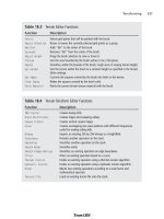
Table 8.4 Selection Tool Options
Option Description
Selection Type Choose one of the selection shapes from this drop-down box. Your choices are
rectangle, square, rectangle or square with rounded corners, ellipse, circle, triangle,
pentagon, hexagon, octagon, one of two star shapes, and one of three arrow shapes.
Mode Normally you would use the Selection tool in Replace mode, where each time you use
the tool, you create a new and different selection. You can use Add mode if you want
each selection you make to be added to the previous selection. Remove mode
removes the area of each selection from a previous selection. You will find, however,
that it is probably best to just use Replace mode and press the Shift key to
temporarily invoke Add mode or the Control key to temporarily invoke Remove mode.
Feathering Feathering controls the sharpness of a selection's edges. By fading a set width (in
pixels) along the edges, it produces a smooth transition between a selection and
the surrounding area. The feathering value is the width of the transition area in
pixels. A higher feathering value creates softer edges by feathering more pixels.
Feathering is useful when pasting a selection. The fading helps the selection blend
into the background.
Anti-alias Anti-aliasing is similar to feathering, but more precise. It produces a smooth-edged
selection by partially filling in pixels along the edge, making them semitransparent. If
anti-aliasing is not applied, the edges of a selection can appear jagged. Anti-aliasing
is useful when combining images and when working with text.
Team LRN
Please purchase PDF Split-Merge on www.verypdf.com to remove this watermark.
3. Click and drag the mouse until the selection is the size you want. As the cursor
moves, a line appears to indicate the border of the selection.
4. Release the mouse button. The selection border becomes a marquee.
Freehand Selection Tool
The Freehand Selection tool shares the same slot in the Tool palette as the Selection tool.
It makes selections with three types of borders:
■
Irregularly shaped borders
■
Point-to-point straight borders
■
Borders between areas of contrasting colors or amount of light
You can change the Freehand Selection tool's selection shape from its Tool Options dia-
log box by choosing one of the three selection shapes from this drop-down box. This
works exactly the same as with the Selection tool.
The Freehand Selection tool has the same options as the Selection tool, with one addition:
Smoothing. This option smoothes sharp corners and jagged lines. The higher the value,
the more smoothing is done.
Use the Freehand Selection tool to draw the outline of the selection as follows:
1. Click the Freehand Selection icon on the Tool palette.
2. On the Tool Options palette, set the needed options.
3. Move the cursor over the image.
4. Click the image at a point that you want to become the border of the selection.
5. Drag the cursor to create an outline of the area you want to select. Be careful
here—don't release the mouse button while creating your selection, or you may
end up selecting stuff you don't want.
6. If you release the mouse button, start again, add to the selection using the Shift
key, or remove part of the selection using the Ctrl key.
7. When the line encloses the selection, release the mouse button. The line becomes a
marquee indicating the border of the selection.
Masks
A mask is a grayscale image that you apply to a layer. You can use it to hide and display
parts of the layer, to fade between layers, and to create special effects with precision. Masks
can be created from selections, alpha channels, and images.
A mask can cover a layer completely or with varying levels of opacity. The gray value of the
mask determines how much it covers. Where it is black, it completely masks the layer; where
it is white, it leaves the layer unmasked; where it is gray, it produces a translucent effect.
Chapter 8
■
Introduction to Textures300
Team LRN
Please purchase PDF Split-Merge on www.verypdf.com to remove this watermark.
All masks are created and edited in a grayscale bitmap mode. Therefore, all tools and
image processing features that work on grayscale images work on masks. The tools that
can be used in either vector or bitmap mode (Drawing, Preset Shapes, and Text) work only
in their bitmap modes when editing masks.
A mask works the same way with a vector layer as it does with a bitmap layer. It can be
linked to a layer, which moves it with the layer. If a mask is not linked to the layer, mov-
ing the layer's content will not affect the position of the mask.
Because a mask is grayscale, you can save it with the image in an alpha channel or as a sep-
arate image on a hard disk. The texture for the helicopter canopy in Figure 8.7 was creat-
ed as a grayscale mask saved in an alpha channel! Also, you can load a selection as a mask
and a mask as a selection from an alpha channel.
Remember that you must choose the mask layer you are editing by selecting it on the
Layer palette before painting so that you edit the mask, not the image. When you are edit-
ing the mask, the colors available to you become those of a grayscale image. When you
click a foreground or background color box, the grayscale palette appears. When you
switch to a nonmask layer, the active color boxes return to their previous colors.
tip
Any painting tool or effect that can be applied to a grayscale image can be applied to a mask.
When you edit a mask, you change either the areas or the level of masking. For example,
painting over an object to mask it changes the area, while making a gradient fill edits the
degree of masking. A gradient fill is where we fill a shape with colors that gradually fade
from one color to another. Usually we use a grayscale gradient when making masks. For
example, we might use a gradient that transitions from dark gray to white. The dark gray
masks more than the lighter grays. As the gradient approaches white, there is less masking
effect.
Creating a New Mask Layer
To create a new Mask Layer:
1. On the Layer palette, click the layer for which you want to create a mask.
2. Choose Layers, New Mask Layer and then choose the type of mask:
■
Show All. This type shows all underlying pixels. All pixels of the mask are
white. Paint the mask with grays or black to hide portions of the underlying
layers.
■
Hide All. This type hides all underlying pixels. All pixels of the mask are black.
Paint the mask with white or grays to show portions of the underlying layers.
Paint Shop Pro 301
Team LRN
Please purchase PDF Split-Merge on www.verypdf.com to remove this watermark.
The mask layer and the selected layer are added to a new layer group. The mask
layer applies to the selected layer only.
3. Use the painting tools to alter the masked area.
4. To view the mask on the image, click the Mask Overlay toggle on the Layer palette,
at the far right of the layer properties palette for the mask layer you created.
tip
To apply a mask to all underlying layers, drag it from the layer group to the main level of the Layer
palette.
Creating a Mask from a Selection
To create a mask from a selection:
1. Use the Selection, Freehand Selection, or Magic Wand tool to make a selection on
a raster or vector layer in the image.
2. Do one of the following:
■
Mask the selected area. To do so, choose Layers, New Mask Layer, Hide
Selection.
■
Mask the unselected area. To do so, choose Layers, New Mask Layer, Show
Selection.
The mask layer and the selected layer are added to a new layer group. The mask
layer applies to the selected layer only.
3. Use the painting tools to alter the masked area if needed.
4. To view the mask on the image, click the Mask Overlay toggle on the Layer palette.
Creating a Mask from an Image
To create a mask from an image:
1. Open the image that you want to use for the mask.
2. Select the image in which you want to create the mask layer.
3. On the Layer palette, click the layer you want to mask.
4. Choose Layers, New Mask Layer, From Image to open the Add Mask From Image
dialog box.
5. In the Source window drop-down list, select the image to use for the mask.
6. In the Create Mask From Group box, select one of the following:
■
Source luminance. The luminance value of the pixel color determines the
degree of masking. Lighter colors produce less masking, darker colors pro-
duce more masking, and transparent areas completely mask the layer.
Chapter 8
■
Introduction to Textures302
Team LRN
Please purchase PDF Split-Merge on www.verypdf.com to remove this watermark.
■
Any nonzero value. Transparent areas completely mask the layer. There is no
gradation to the masking. Pixels with data (opacity of 1 to 255) become
white pixels in the mask, and transparent pixels become black in the mask.
■
Source opacity. The opacity of the image determines the degree of masking.
Fully opaque pixels produce no masking, partially transparent pixels create
more masking, and transparent pixels produce full masking.
7. To reverse the transparency of the mask data, select the Invert Mask Data check
box. Black pixels become white, white pixels become black, and grays are assigned
their mirror value.
8. Click OK.
The mask layer and the selected layer are added to a new layer group. The mask
layer applies to the selected layer only.
9. To view the mask on the image, click the Mask Overlay toggle on the Layer palette.
Scaling Images
You may need to scale your image, making it larger or smaller. To do this, use the Resize
feature, as follows:
1. Choose Image, Resize.
2. Select a method for resizing the image. The Resize dialog box presents you with
two sizing method options:
■
Pixel Dimensions. Select a new size by choosing a new measurement in pix-
els or one based on a percentage increase or decrease from the original.
■
Actual/Print Size. Select a new size by changing the resolution or the page
dimensions. Note that the two are linked.
3. Enter the new measurements in the Width and Height boxes of the Pixel Dimen-
sion panel. In the Actual/Print Size panel, you can also change the resolution.
4. In the Resample Using box, select the type of resizing for Paint Shop Pro to apply.
There are five choices:
■
Smart Size. Paint Shop Pro chooses the best algorithm based on the current
image characteristics.
■
Bicubic Resample. Paint Shop Pro uses a process called interpolation to min-
imize the raggedness normally associated with expanding an image. As
applied here, interpolation smoothes out rough spots by estimating how the
"missing" pixels should appear and then filling them with the appropriate
color. It produces better results than the Pixel Resize method with photoreal-
istic images and with images that are irregular or complex. Use Bicubic
Resample when enlarging an image.
Paint Shop Pro 303
Team LRN
Please purchase PDF Split-Merge on www.verypdf.com to remove this watermark.
■
Bilinear Resample. Paint Shop Pro reduces the size of an image by applying
a method similar to the Bicubic Resample. Use it when reducing photorealis-
tic images and images that are irregular or complex.
■
Pixel Resize. Paint Shop Pro duplicates or removes pixels as necessary to
achieve the selected width and height of an image. It produces better results
than the resampling methods when used with hard-edged images.
■
Weighted Average. Paint Shop Pro uses a weighted-average color value of
neighboring pixels to determine how newly created pixels will appear. Use
this type when reducing photorealistic, irregular, or complex images.
5. In an image with more than one layer, select the Resize All Layers check box to
resize the entire image. Leave the box unchecked to resize only the active layer.
6. To change the proportions of the image, select the Maintain Aspect Ratio of check
box and type a new ratio for the image width. Aspect ratio is the relationship of the
image's width to height. By default, the Aspect Ratio box displays the image's cur-
rent aspect ratio.
7. Click OK to close the dialog box and apply the changes.
tip
After resizing, many images can be improved by using the Sharpen or Soften filters.
Bilinear and Bicubic resampling are available only for grayscale images and 24-bit images.
To resample an image with a lower color depth, do the following:
1. Increase the image's color depth.
2. Resize the image.
3. Reduce the image's color depth to the original depth.
Rotating
Use this feature to rotate a selection, a layer, or an image of any color depth.
To rotate an image, a layer, or a selection:
1. Choose Image, Rotate, Free Rotate.
2. Select the direction of rotation by clicking the Direction's option button or its text.
Right is clockwise, and left is counterclockwise.
3. Set the degrees of rotation in quarter-circle increments (90-, 180-, or 270-degree
option) or rotate by any other amount by typing the value in the Free box.
4. To rotate every layer in a multilayer image, select the All Layers check box. Clear
the check box to rotate only the current layer. When this check box is selected or
Chapter 8
■
Introduction to Textures304
Team LRN
Please purchase PDF Split-Merge on www.verypdf.com to remove this watermark.
when the image consists of a single background layer, the canvas size changes to
accommodate the rotated image.
5. Click OK to close the dialog box and rotate the image.
Image Sizes
Use the Change Canvas Size dialog box to change the dimensions of the image. Because
the current background color is used for pixels added to the background layer of an
image, select a background color before opening the dialog box.
Changing the canvas size changes the size of the background, without changing the size of
the image or any layers that may be in the image.
To change the image resolution, use the Resize dialog box, not the Canvas Size dialog box.
To change the size of the image canvas:
1. Choose Image, Canvas Size.
2. In the Dimensions panel, enter a new size (in pixels) for the image in the New
Width and New Height boxes. You can type a number or use the spin controls. The
current width and height are displayed for your reference.
3. Use the Arrow buttons in the dialog box to indicate how you want the image to be
placed in the newly dimensioned canvas.
4. Use the edit boxes to enter precision placement information that will supersede the
Arrow buttons, if needed.
5. After positioning the image, click OK to close the dialog box and apply the
changes.
Text
There will be times when we want our game textures and images to contain text. Now we
could use the paintbrush and try to write out our text in a freehand fashion. However,
there just so happens to be a very handy Text tool available with lots of capabilities.
Looking back to Figure 8.27, you'll find that the Text tool is the fourth one from the bot-
tom of the Tool palette.
Go ahead and create a new blank image, then select the Text tool, and click in the center
of your image. You'll get the Text Entry dialog box.
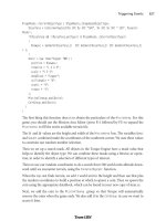
Using Figure 8.33 as your guide, you'll note that the first and most obvious feature is the
Text Edit box. You can type many lines of text in here; there is a limit, but it is high. I have
been able to enter 32 lines of 128 characters each with no penalty other than a little slow-
down in response time.
Paint Shop Pro 305
Team LRN
Please purchase PDF Split-Merge on www.verypdf.com to remove this watermark.
Let's create some text so that we can look
more closely at the available options.
1. In the Font section of the Tool Options
palette, you can scroll through the Name,
Stroke Width, and Size lists and click to
make your selection.
2. The Create As section is where you
choose the creation mode for the text.
You can select one of three modes:
■
Ve ct o r. A vector object on a vector layer.
■
Selection. An empty selection on the current layer.
■
Floating. A selection floating above the current layer.
You should usually create your text as vector type. This allows you to easily edit
and manipulate the text at any time. You can collapse the vector text into your
bitmap image when you are happy with using the Layers, Merge, Merge All (Flat-
ten) menu item.
3. By selecting the Anti-alias check box, you can soften the jagged edges that can
appear on bitmap text; this feature partially fills in pixels in the jaggy spots. You
can only do this with grayscale and 24-bit color images, however. (You should cre-
ate your textures as 24-bit color images unless you have a specific reason to do oth-
erwise, anyway.)
4. To select a color for the text, use the Materials palette.
5. Add emphasis effects to the text by using the Font Style options. When you choose
an effect, it is applied to the next character you type. Change the effects of specific
characters by highlighting them and then clicking the effects buttons. You can
select from four style effects: Bold, Italic, Underline, and Strikeout.
6. The Alignment buttons are to the left of the Font Style buttons. These buttons set
how the ends of multiple lines of text line up with each other: left, center, or right
paragraph alignment. These settings affect the entire text in a paragraph and can't
be changed for individual lines. Different paragraphs can have different alignments.
7. In the Text Settings section at the far right end of the Tool Options palette, set spe-
cific leading (space between lines) and kerning (space between letters) by clearing
the Auto Kern check box and typing values in the Leading and Kerning edit boxes.
If you cannot see the Text Settings section, you will see a small black triangle at
the right end. Click on this triangle to make the Tool Options palette shift over,
revealing the tools that couldn't fit in your window on the right-hand side.
Chapter 8
■
Introduction to Textures306
Figure 8.33 The Text Entry dialog box.
Team LRN
Please purchase PDF Split-Merge on www.verypdf.com to remove this watermark.
8. In the text box, type the text you want to add to the image. Click the background
(away from the text) to remove the highlighting and view the text. Note that the
text does not display kerning and leading changes you have made.
9. Click OK to close the dialog box; this places the text in the image at the location
where you had clicked with the Text tool.
There you go. You should now have your text sitting in your image, centered on the spot
where you clicked the Text tool, highlighted with a dashed-line box with the sizing han-
dles on the corners.
Moving Right Along
In this chapter we had our first peek at the world of textures. As the book unfolds, we will
examine the uses for textures in more detail.
Then we took a detailed look at a powerful imaging tool that we can use to create and edit
textures—Paint Shop Pro. As you have seen, Paint Shop Pro has a very complete feature set.
In the following chapter, we will expand our understanding of using textures in game
development by learning how to skin objects, such as player models and vehicles.
Moving Right Along 307
Team LRN
Please purchase PDF Split-Merge on www.verypdf.com to remove this watermark.
This page intentionally left blank
Team LRN
Please purchase PDF Split-Merge on www.verypdf.com to remove this watermark.
309
Skins
chapter 9
S
kins are special textures used in games. The quality that separates skins from regu-
lar textures is that they typically wrap around the shape of a 3D model. It is fairly
obvious that 3D monsters and player-characters would have texture skins, but the
term can also apply to automobiles, wheelbarrows, mailboxes, rowboats, weapons, and
other objects that appear in a 3D game.
Typically, skins are created after a model has been unwrapped, so that the skin artist
knows how to lay the skins out in the UV template. We're going to do the process a bit
backward, simply because we should stay on topic with Paint Shop Pro and textures until
we've covered the topic sufficiently.
In our case here, it isn't a big issue anyway, because I'm providing you with UV templates
from previously UV unwrapped models to work with.
UV Unwrapping
UV unwrapping is a necessary function prior to skinning a model. Consider it part of the
modeling process in the context of this book. However, in this chapter we'll deal with the
texture processing part of skinning a model and use models I've provided on the CD. Later
you'll create and skin your own models and do the unwrapping and other things. We'll
cover how the unwrapping works in more detail then.
When we want to apply textures to 3D objects, we need a system that specifies where each
part of a texture will appear on which parts of a model. The system is called U-V
Coordinate Mapping. The U-coordinate and the V-coordinate are analogous to the X- and
Y-coordinates of a 2D coordinate system, though they're obviously not exactly the same.
Team LRN
Please purchase PDF Split-Merge on www.verypdf.com to remove this watermark.
Imagine (or you can actually try this at home yourself) taking a closed cardboard box and
slicing it open along the edges. Then lay the whole thing out flat on the kitchen table, with
no parts overlapping parts. There, you've unwrapped your box. Now get out your crayons
and draw some nifty pictures on it. Then glue it all back together again to make a box. I
think you get the idea.
With UV unwrapping we apply the technique to some complex and irregular shapes, like
monsters and ice cream cones.
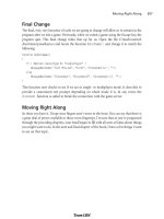
The Skin Creation Process
When we begin the skinning process, we will have a bare, unadorned 3D model of some kind.
For this little demonstration, we'll use a simple soup can (see Figure 9.1). It's a 12-sided cylin-
der with a closed top and bottom (end caps). Each side face is made up of two triangles, and
the end caps are made of 12 triangles each, for a total of 48 triangles. Nothing too special here.
Using the UV Unwrapping tool, we have to basically spread
all our faces out over a nominally flat surface (see Figure 9.2).
We save the image of the UV template, plus we save the
original model file, because the UV Unwrapping tool will
have modified the UV coordinates for the objects in the
model, and we can save those changes to the file so that the
modeling tool can read them back in again.
Then we import the unwrapped image with the lines indi-
cating the face edges into an image processing tool like
Paint Shop Pro and apply whatever textures, colors, or sym-
bols we need, such as shown in Figure 9.3.
Notice that for textures I simply created mark-
ings and re-created a simple label. For the top
of the can I made some circular text, and for
both end caps I made a circular pattern that
represents the ridges you often find in those
places on tin cans. The image file has now offi-
cially become a skin for the can!
The final step is to import the new skin into
the modeling program (or the game) and view
the results, as in Figure 9.4.
The part of the process we will focus on in this
chapter is the activity shown in Figure 9.3, the
actual creation of the textures on the UV
Chapter 9
■
Skins310
Figure 9.1 The victim—a
simple can of soup.
Figure 9.2 Laying it all out—the
unwrapped can.
Team LRN
Please purchase PDF Split-Merge on www.verypdf.com to remove this watermark.
template, so that it can be later used
as a skin for models.
Making a Soup
Can Skin
So let's dive right in and create a skin.
We can use the bare model of the
soup can I showed you in the last sec-
tion. The procedure has quite a few
steps—more than 30—so we'd better
roll up our sleeves and get to it.
The Soup Can Skinning
Procedure
This is how you skin a soup can:
1. Open C:\3DGPAi1\resources\ch9\can.bmp in Paint
Shop Pro. This file contains the UV mapping template.
tip
Remember when I said that the only file types we would need to
use are JPG and PNG in the last chapter? Well, that was sort of a
lie, though not quite—you see, the only file types we will be using
for
making games
will be those two types. However, the UVMap-
per program outputs its UV mapping templates as one of two
types: BMP (Windows bitmap) or TGA (Targa) format. So I've
picked BMP to be our standard UV mapping template format. We
won't be creating any game files in this format, however.
2. Choose Image, Increase Color Depth, 16 Million Colors. You need to do this to get
access to the full palette.
3. Save the file as C:\3DGPAi1\resources\ch9\mycan.psp. This way you can re-use the
layers over and over at later times if necessary. Make sure you save your work often
as you follow the steps, in case you royally mess up, like I frequently do.
4. Right-click the Layer palette (see Figure 9.5), and then choose New Raster Layer.
5. Accept the default settings and click OK.
6. Click Raster 1 to make that layer active.
7. Click the Preset Shape tool, third icon from the bottom of the Tools toolbar on the
left.
Making a Soup Can Skin 311
Figure 9.3 After applying textures.
Figure 9.4 Aha! Not such
a simple can anymore.
Nutritious, too!
Team LRN
Please purchase PDF Split-Merge on www.verypdf.com to remove this watermark.
8. In the Tool Options palette
(if it is not visible, choose
View, Palettes, Tool
Options to make it visible),
click the Shapes List icon.
The Shapes List will
appear, as in Figure 9.6.
9. Choose the Rectangle
from the Shapes List
control; the list will go
away automatically.
10. If the Create As Vector box
on the Tool Options
palette is checked, clear it.
11. If the Retain Style box on
the Tool Options palette is
checked, clear it.
12. In the Materials palette, locate the Fore-
ground and Stroke Properties control. It is
the upper-left box in the larger pair of boxes
in the Materials palette.
13. Along the bottom of the Foreground and
Stroke Properties are three buttons. Click the
one on the far right with the No Entry icon,
called Transparent. Now that it is depressed,
the foreground or stroke of the object you
draw will be transparent.
14. Click the Background and Fill Properties control, the lower-right control of the
larger pair of boxes in the Materials palette. When the Color dialog box opens,
select a bright red, and make sure it appears in the box marked Current. Then click
OK to close the dialog box.
15. Now draw a rectangle that completely covers the rectangle containing the triangles
in the middle of your mycan.psp image, as in Figure 9.7.
16. Now use the Background and Fill Properties control to set the fill to white, and
draw a thin white rectangle across the middle of the red rectangle you just made
(see Figure 9.8).
So now you have your basic red-and-white pattern on the sides of the can. If you
look at Figure 9.3 again, you'll notice that the red blends into the white gradually.
There are several ways to do this. For example, you could have used a gradient fill
Chapter 9
■
Skins312
Figure 9.5 Materials and Layer palettes.
Figure 9.6 The Shapes List.
Team LRN
Please purchase PDF Split-Merge on www.verypdf.com to remove this watermark.
in the rectangles you created. But you're going
to use another method, one that is more of a
touchup technique.
17. First, you're going to select the sides of the can.
Use the Square Selection tool (fifth icon down
on the Tools toolbar) to select the entire rectan-
gle that encloses all of the red and white rectan-
gles you've just made, but only those areas. Use
Figure 9.9 as a guide.
18. Next, soften the transition between the red and
the white. Choose Adjust, Softness, Soft Focus.
You will get the Soft Focus dialog box, as
shown in Figure 9.10.
19. Set all of the values in the boxes to 100 percent,
except for Halo size. Set Halo size to 70 per-
cent, and then click OK to close the box. You'll
see the edges between the red and the white go
blurry.
20. Repeat the last two steps—choose Adjust, Soft-
ness, Soft Focus, and then make sure all values
are set to 100 percent (except Halo Size, which
is set to 70 percent) and close the dialog box.
There now—you have your blended pattern.
21. Next you'll want to add metal lips to the top
and bottom of the can sides. Do this by creat-
ing a thin light gray rectangle all the way across
the top and another at the bottom, as shown in
Figure 9.11. The black arrows indicate the loca-
tion of the lip line.
22. Now you'll want to create the surface texture
for the ends, or lids, of the can. Once again,
select the Preset Shape tool.
23. In the Tool Options palette, click on the Shapes
List icon.
24. Choose the Ellipse from the Shapes List control.
25. This time make sure that the Create as vector box is checked.
Making a Soup Can Skin 313
Figure 9.7 The red rectangle.
Figure 9.8 The white rectangle.
Figure 9.9 Selecting the mapped
sides of the can.
Team LRN
Please purchase PDF Split-Merge on www.verypdf.com to remove this watermark.
26. Set the foreground color to a light
gray and the background color to
transparent, using the same technique
you used when drawing the rectangles
earlier.
27. Draw a series of concentric ellipses in
both the top and bottom list shapes
(see Figure 9.12). Make sure to leave a
sizable gap between the inner ellipse
and the one next to it.
Also use a line width of about 15 for
the outermost ellipse, 2 for the middle
ellipse, and 4 for the innermost one.
The ellipses are drawn from the center
out. You may need to fiddle a bit
before you get it right.
tip
You can adjust the size of your vector object ellipses by grabbing
the little black handles on the shapes while the object is selected.
If it isn't selected, use the Object Selection tool (the bottom tool
of the Tools toolbar) to select your ellipse by clicking on it.
You can also drag your ellipses around this way. Press Ctrl+Left
Arrow to nudge the object a bit to the left. Press the Ctrl key with
the other arrow keys to nudge the object in other directions.
28. Next, select the Text tool, which is fourth
from the bottom of the Tools toolbar. If
you have any objects already selected, des-
elect them by clicking the Object Selec-
tion tool on an empty part of the image
before selecting the Text tool.
29. As you move the Text tool cursor around,
it will have an icon like the one on the left
in Figure 9.13. When you move it over a
vector object, the cursor will change to
the one on the right in Figure 9.13.
Move the cursor over the top part of the
innermost ellipse object in the upper set
of concentric rings.
Chapter 9
■
Skins314
Figure 9.10 Soft Focus dialog box.
Figure 9.11 Adding the metal
lips.
Figure 9.12 Adding the ridges.
Team LRN
Please purchase PDF Split-Merge on www.verypdf.com to remove this watermark.
30. Now click on that object; you will get the Text Entry
dialog box. Select the font you want from the Tool
Options palette.
31. Use a font size of 12 and make sure you set the
stroke width to 1.0.
32. Type in your text, something like 16 Fluid Ounces.
33. Make sure you have vector set in the Create As control; then click Apply.
34. Voilá! You will have text that follows the curve of the ellipse around in an arc.
35. Now add your main label text using the Text tool. You can type whatever you want
and position it wherever you want.
36. When you are finished, save your file one final time as
C:\3DGPAi1\resources\ch9\mycan.psp. This is your source file.
37. Next, save your work as C:\3DGPAi1\resources\ch9\mycan.jpg. Make sure you've
selected the "JPEG – JIFF Compliant" type in the Save As dialog box when you do
this.
38. You will get an alert saying that it will have to save the file as a merged image and
asking if you want to continue. This is expected because the JPG format doesn't
support layers. Click Yes.
Testing the Soup Can Skin
Congratulations! You've made your first skin! I suppose now you want to see what it looks
like all wrapped around a tin can and everything. Okay, so do this:
1. Browse your way to C:\3DGPAi1 and then double-click on the Show Book Models
shortcut.
2. The Torque Engine will fire up with a special program called the Show Tool. Click
on Load Model.
3. Find mycan.dts and load it.
4. Presto! That's your skin on that there soup can! Good job!
5. You can admire your creation in all its splendor by using the navigation keys to
move the can back and forth and rotate it about the various axes. See Table 9.1 for
the Show Tool key commands.
6. You can view my original soup can skin by loading the soupcan.dts model.
Making a Soup Can Skin 315
Figure 9.13 Text tool cursors.
Team LRN
Please purchase PDF Split-Merge on www.verypdf.com to remove this watermark.
Making a Vehicle Skin
Okay, soup cans are cool and soup hits the spot, too. But now that lunch break is over, let's
move on to something a bit more serious. Many people are going to have vehicles in their
games, and the Torque Engine does quite a nice job of supporting vehicles. We'll be mak-
ing our own vehicles later, but because this chapter is on creating skins, let's make a skin
for some kind of vehicle.
For a bit of a tease, let's take a look at a vehicle that is already included in the Torque demo
using the Show Tool.
1. Browse to C:\3DGPAi1 and click on the Show Racing Models shortcut. This is not
the same shortcut as Show Book Models.
2. Click Load Shape.
3. From the list, select buggy.dts, which is near the bottom.
4. Zoom in using the navigation keys and take a gander at the buggy chassis. Pretty
cool, huh? Notice that it has no wheels. In Torque we model the wheels separately,
so that we can model the suspension action of the vehicle more accurately.
The Dune Buggy Diversion
Okay, okay. I knew you would want to do this, so I'll show you how to test-drive the dune
buggy in-game, as long as you promise to come back here after you've tired out your dri-
ving fingers. People tend not to learn quite as well when they are pouting.
1. Browse to C:\3DGPAi1 and click on the Run racing Demo shortcut.
2. Click on Start Mission.
3. In the Launch dialog box, make sure that the Multiplayer Mission box is cleared.
4. Select Car Race Track from the mission list.
5. Click Launch.
Chapter 9
■
Skins316
Table 9.1 Torque Show Tool Navigation Commands
Key Description
A rotate left
D rotate right
W bring closer
S move farther away
E rotate top backward
C rotate top forward
Team LRN
Please purchase PDF Split-Merge on www.verypdf.com to remove this watermark.
6. After the game loads, have at it! You probably should switch to Chase view by
pressing the Tab key—there's more to see. See Table 9.2 for the keyboard controls.
The Runabout Skinning Procedure
Okay, now that the old adrenaline is pumping, let's get back to making skins. We're going
to create a skin for a less ambitious, but still pretty cool, vehicle—the runabout. It's a fic-
tional creation of mine that's a convergence of memories of summers spent reading Doc
Savage pulp stories and memories of a classic 1936 Auburn Boattail Speedster that I saw
at a car show once as a teenager.
1. Open C:\3DGPAi1\resources\ch9\runabout.bmp in Paint Shop Pro. This file con-
tains the UV mapping template.
This time, I've unwrapped the object differently. If you recall, the soup can was
completely unwrapped so that each individual face was lying flat. This time I
unwrapped the runabout by showing only the separate objects (except the cab)
from one particular view—the side or the top.
By doing this, I can treat each of these objects as symmetrical, with the hidden side
being simply a mirror image of the visible side. This is another valid technique, but
it does have some pitfalls, which we will encounter. The advantage of using this
approach is that it saves on image editing time, because only half of the objects'
surfaces need to be given textures.
2. Select the Pen tool (second from the bottom). Set the line color to red and the fill
to transparent.
3. Select Segment Type to be Point to Point on the Tool Options palette, as shown in
Figure 9.14.
Making a Vehicle Skin 317
Table 9.2 Torque Racing Demo Controls
Key Description
mouse steering left or right
W accelerate
S brake
Tab toggle from first- to third-person viewpoint
Escape exit the game
Figure 9.14 Point to Point Segment Type button.
Team LRN
Please purchase PDF Split-Merge on www.verypdf.com to remove this watermark.
4. Using the selected object with the thicker
lines in Figure 9.15 as a guide, trace a
shape around the cab triangles that cover
the roof and the C-pillar. You click at a
start location and then click again at each
place around the cab where the object's
line will change direction. Each click
defines a node of the object.
5. When you have made the last node of your
object, click on the Object Selection tool
(bottom icon of the Tools toolbar). The
object will now be surrounded by a rectan-
gle with reshaping handles (black squares).
6. If you are not happy with the shape you've made, select it again with the Object
Selection tool (if it isn't already selected), and then click the Pen tool. In the Tool
Options palette in the Mode section, click on the little white arrowhead icon,
which is the Edit Mode button (see Figure 9.16).
7. Move your cursor down to your object and reshape the object by grabbing and
moving the little square node handles (see Figure 9.17) that are located at the
places where you clicked when creating the object—these are the nodes.
8. Once you've finished, change the fill color of the object
you've just created to the color of your choice, and make
the line color transparent. By drawing the object in this
way, you don't have the fill color obscuring your template
while you trace the outline. Using red line color when you
are drawing helps to differentiate between the template's
black lines and the lines you are making.
9. After you've finished with the cab roof, right-click any-
where on the drawing to deselect the object you just drew,
and then set the line color back to red and the fill color
back to transparent.
10. Next, draw an outline around the entire cab template, fol-
lowing the outside edges. When finished, click the Object
Selection tool.
Chapter 9
■
Skins318
Figure 9.15 Tracing the cab roof.
Figure 9.17 Arrows
indicate the editable
node handles.
Figure 9.16 Edit Mode button.
Team LRN
Please purchase PDF Split-Merge on www.verypdf.com to remove this watermark.
11. Set the fill of this new object to a dark green-gray color, and set the line color to
transparent. The new object should now obscure both the earlier roof object plus
the rest of the cab template.
12. Select the new object with the Object Selection tool, and then choose Objects,
Arrange, Send to Bottom. This will move the last object you created to be posi-
tioned underneath the first object you made that covered the roof. See Figure 9.18
to see what the before and after should look like.
13. Next, create a new raster layer by right-clicking the Layer palette and choosing New
Raster Layer. Accept the defaults and click OK in the dialog box that appears.
14. Now find the Paint Brush tool (the seventh one down), but instead of just clicking
the icon, click the little black triangle or arrow on the right side of the icon. A pop-
up icon list will appear, from which you should select the Air Brush.
15. Set your foreground color to be the
same blue (or whatever) color you
used for the cab roof.
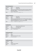
16. Now set your Air Brush tool options
to match those in Table 9.3.
17. Use the Air Brush to spray over the
outline of the car's body, as shown
in Figure 9.19. Remember to make
sure that the new raster layer you
created (probably called Raster 1) is
selected in the Layer palette, other-
wise your airbrushing will be
applied to the wrong layer.
Making a Vehicle Skin 319
Figure 9.18 Before using Send to Bottom, and
after using it.
Table 9.3 Air Brush Settings
Setting Value
Shape Round
Size 32
Hardness 9
Step 1
Density 100
Thickness 100
Rotation 0
Opacity 35
Blend Mode Normal
Rate 5
Team LRN
Please purchase PDF Split-Merge on www.verypdf.com to remove this watermark.
18. Now change to a light blue foreground
color, and set the Air Brush size to 16
and the opacity to 12.
19. Spray on the accent color, as shown
in Figure 9.20. When I did it, I
sprayed one long line from left to
right, and then I went back and used
short spurts to make the line more
irregular.
20. Next you'll apply a fancy racing stripe.
Select the Pen tool, and change it to
Drawing Mode by clicking on the little
pencil icon next to the Edit Mode
arrow we used earlier.
21. Make sure that Create as vector is set in the Tool Options palette, and then select
Freehand for the Segment Type, also in the Tool Options palette.
22. Set the line color to be yellow.
23. Draw a squiggly line, with a shape like the one in Figure 9.21, from left to right on
the car body. You can edit the shape of the line by twiddling the node handles, just
like you did earlier when we made the cab roof. To make your line look more like
Figure 9.21, choose the Object Selection tool, and deselect the line.
So, there you have it—the car's body paint job is done. Notice that we used a different
approach than we did with the cab. It just goes to show that there's more than one way to skin
a cat…er, car! I meant car! Honest.
Well, I guess it's time to get back to work. The last bits left are the four wheel-well, fend-
er thingies. We'll do these in a fashion similar to the way we did the cab.
24. Using Figure 9.22 as a reference and using the Pen tool set to Point to Point Seg-
ment Type, draw an outline of the upper part of the upper-left fender thingy and
fill it with the basic blue we've been using.
25. After creating the last node, choose the
Object Selection tool and make sure
the object you just made is selected.
26. Choose Edit, Copy to copy the object
to the Clipboard.
27. Choose Edit, Paste, Paste As New Layer.
The new object will be pasted in its
own layer.
Chapter 9
■
Skins320
Figure 9.19 Spray-painting the body base color.
Figure 9.20 Spray-painting the accent color.
Figure 9.21 Adding the racing stripe.
Team LRN
Please purchase PDF Split-Merge on www.verypdf.com to remove this watermark.
28. Choose Image, Mirror. This will cause your
new object to face left instead of right, or
vice versa. This is why I used Paste as New
Layer, instead of Paste as New Vector Selec-
tion. When you use the Image, Mirror
menu or the Image, Flip menu, all the
objects on the current layer are affected. By
creating a new layer with just the one
object, you avoid this problem.
29. Place your new copy of the object over
the upper-right fender thingy template,
adjusting it with the Pen tool in edit
mode if necessary.
30. Repeat steps 24 to 29 for the bottom two fenders.
31. Now repeat all of steps 24 to 30, but this time create the fender skirts with a fill
color of yellow, which stylishly matches the racing stripe.
32. When you are finished, save your file one final time as
C:\3DGPAi1\resources\ch9\myauto.psp. This is your source file.
33. Now save your skin as C:\3DGPAi1\resources\ch9\myauto.jpg.
34. Once again, you will get an alert saying that the software will have to save the file
as a merged image, and asking if you want to continue. Choose Yes.
Testing the Runabout Skin
Now it's time to take our little creation out for a spin around the block, so to speak.
We'll use the Show Tool just like we did with the soup can.
1. Browse your way to C:\3DGPAi1 and then double-click on the Show Book Models
shortcut.
2. The Torque Engine will fire up the Show Tool. Click on Load Model.
3. Find myauto.dts and load it. A fine job, indeed! Notice the lack of wheels, the same
as with the dune buggy you looked at earlier.
4. Don't forget to use the navigation keys to move the car back and forth, and rotate
it about the various axes. See Table 9.1 for the Show Tool key commands.
5. You can view my original runabout skin by loading the runabout.dts model.
Unfortunately, we'll have to wait until the later modeling chapters before we can take the
runabout out for a real test drive. That's okay, though—we've plenty to do in the meantime!
Making a Vehicle Skin 321
Figure 9.22 The fender thingies.
Team LRN
Please purchase PDF Split-Merge on www.verypdf.com to remove this watermark.