Tài liệu 3D Game Programming All in One- P16 docx
Bạn đang xem bản rút gọn của tài liệu. Xem và tải ngay bản đầy đủ của tài liệu tại đây (1.4 MB, 30 trang )
Then choose Image, Rotate, Free Rotate to get the Free
Rotate dialog box (see Figure 11.9).
Click the Right button in the Direction frame, and click the
Free button in the Degrees frame. Finally, type 1.00 in the text
box next to the Free button, and click OK. This will rotate the
selected area 1 full degree to the right (see Figure 11.10).
You should have your rotated area with the selection mar-
quee still surrounding it. Don't touch anything yet—leave
the selection as it is.
Now after having explained the Crop
tool, I'll show you another way to
crop the image that is sometimes
more convenient than using the
Crop tool. With the rotated area still
selected, choose Image, Crop to
Selection and the image will be cropped for you!
You will then end up with an image as shown in
Figure 11.11 suitable for use as a texture.
Now compare Figure 11.11 with Figure 11.7
and you will see the difference.
Original Artwork
The other approach to creating textures is to
use original artwork. Some people believe this
is not a real option for them, because they
think they can't draw or paint to save their
lives. I tend to feel that everyone can learn the
techniques required. My intent here, however,
is not to teach you how to draw, so if you want
to learn more, I encourage you to look into tak-
ing some lessons.
If you are satisfied with your artistic skills, then
you have another rich avenue for texture gen-
eration available to you. The techniques used to convert a photograph to a texture can also
be used to convert your hand-made images to textures.
Another approach for creating original artwork is to create your images directly in a tool
like Paint Shop Pro. You can draw freehand using the mouse or a pen tablet.
Sources 357
Figure 11.8 Rectangular
Selection tool icon.
Figure 11.9 The Free Rotate dialog box.
Figure 11.10 The rotated woodgrain.
Figure 11.11 The cropped woodgrain
image.
Team LRN
Please purchase PDF Split-Merge on www.verypdf.com to remove this watermark.
With tools like Paint Shop Pro you have a wide variety of means for creating textures,
including a specific Texture Effects tool in the Effects menu, as shown in Chapter 8. Figure
11.12 shows examples of textures created using the built-in features of Paint Shop Pro. I
encourage you to explore this tool in depth. It can really be a timesaver. And you can use
it to create some knockout textures.
Scaling Issues
When creating your textures, you will need to pay
attention to the issue of scale. The sizes of the things
within an image that is used to make a texture have a
particular relationship to other real-world objects. We
are subconsciously aware of many of these relation-
ships from our exposure to the world in general and
will notice when the textures are out of proportion to
the items they adorn. If it's bad enough the effect can
sometimes be similar to the sound of fingernails being
dragged across a chalkboard!
Figure 11.13 shows two stylized houses.
The bricks in house A are far too large,
while the bricks in house B are more
appropriately sized, yet may still be a bit
too large. Yes, there are some uses for
stone blocks having proportions such as
those in house A, but they are rarely
used in bungalow-sized or two-story
homes, as depicted in the figure.
The scale issue can pop up anywhere, as you
can see in Figure 11.14. The texture image in
the corrugated metal bridge surface is probably
about 10 times larger than is appropriate.
Sometimes you might need to redo the texture
to match—other times you can adjust how the
texture is applied to the polygons using the
modeling tools. My rule of thumb is that if the
texture image size is 64 pixels by 64 pixels or
smaller and needs to be made larger, you
should make a new texture at the larger size.
The same goes the other way: If the image size
Chapter 11
■
Structural Material Textures358
Figure 11.14 Scaling error.
Figure 11.13 Scaling bricks.
Figure 11.12 Example textures.
Team LRN
Please purchase PDF Split-Merge on www.verypdf.com to remove this watermark.
is larger than 64 pixels by 64 pixels and needs to be made smaller, then make a new tex-
ture at the smaller size.
Tiling
Many structures have large surfaces with repeating patterns. The best way to approach
making textures for these surfaces is to create one smaller texture that is replicated many
times across the surface, rather than simply making one large texture.
The replication will usually take place in two dimensions. It is important to make sure that
the edges of the texture align properly when they meet. Figure 11.15 shows this to good
effect. You can see the obvious horizontal as well as the more subtle artifacts in house A
where the tiled brick textures don't quite line up. In house B, where care was taken to
ensure that the texture edges matched up correctly, those artifacts aren't visible.
However, in house B in Figure 11.15 there
is another obvious artifact of tiling, this
time caused by asymmetric lighting
effects in the texture shading. You can see
each repeated texture tile—its position is
marked by the presence of the darker
shaded bricks in a repeated pattern. This
effect can be quite subtle and difficult to
detect in an image viewed in isolation.
Figure 11.16 shows the texture used in house B of Figure
11.15. Looking at it in isolation, you would be hard
pressed to notice the subtly darker shaded bricks.
The simplest way to fix up a texture for use as a tiled tex-
ture is to copy the left edge, about 5 or 10 pixels wide,
mirror the copy horizontally, and then paste the copy on
the right side of the image. Do the same for the bottom
edge. Of course, you can go from top to bottom or right
to left as well. The important step is the mirroring.
After placing the mirrored edges, spend a little time
blending their inner edges with the interior portions of
the image.
Figure 11.17 shows a stone block texture that is a candi-
date for use in a tiling situation.
Figure 11.18 shows the texture tiled in a set of four. Again,
you can see the artifacts caused by the mismatched edges.
Tiling 359
Figure 11.15 Tiled brick texture.
Figure 11.17 A stone texture.
Figure 11.16 The brick texture
with asymmetric shading.
Team LRN
Please purchase PDF Split-Merge on www.verypdf.com to remove this watermark.
Figure 11.19 shows the
left edge being copied,
mirrored, and placed
on the right.
Figure 11.20 shows the
same thing happening
with the bottom edge.
Finally, Figure 11.21
shows the tiled result.
Texture Types
There are far too many
texture types and class-
es of material appear-
ances for me to enu-
merate them with any
sort of thoroughness.
Given that, there is a
much smaller set of tex-
ture types that are
found over and over in
nature and man-made
structures.
Most of the following textures are types that are used for buildings, bridges, and other
man-made items in a game world.
Irregular
Irregular textures tend to have a general disorder and
random appearance, like that shown in Figure 11.22. Dirt
and grass are examples of irregular textures. Quite often
irregular textures are combined with other, different
irregular textures in order to give a weathered or dam-
aged appearance to an area or surface.
Chapter 11
■
Structural Material Textures360
Figure 11.18 Poorly tiled stone
texture.
Figure 11.19 Replicating the
left edge.
Figure 11.20 Replicating the
bottom edge.
Figure 11.21 Properly tiled
stone texture.
Figure 11.22 An irregular
texture.
Team LRN
Please purchase PDF Split-Merge on www.verypdf.com to remove this watermark.
Rough
Rough textures, as shown in Figure 11.23, sometimes
have somewhat the same sense about them as irregular
textures. They are often used as tiles on a surface like a
sidewalk or rough concrete walls.
Pebbled
Pebbled textures are another example of textures often
used for paved surfaces and stone walls. Tarmacadam
pavement is an example of a finely pebbled surface when
viewed from a distance
of about 5 or 6 feet.
Figure 11.24 shows a
more obvious pebbled
texture that could be
used for a wall or deco-
rative planter.
Woodgrain
Figure 11.25 shows a
woodgrain texture that
has many highly variant
bundles of lines rang-
ing from fine to coarse that run roughly parallel to each
other, sometimes interrupted by swirls and knots. Some
kinds of stone have similar appearances.
Smooth
We all know when something is smooth—there are no
discernable bumps or irregularities to our touch.
Depicting smoothness in textures can be a little diffi-
cult. We usually create a rather bland surface look and
then introduce a few soft and mild irregularities in
order to emphasize the smoothness. Figure 11.26
shows a smooth texture.
Texture Types 361
Figure 11.23 A rough texture.
Figure 11.24 A pebbled
texture.
Figure 11.25 A woodgrain
texture.
Figure 11.26 A smooth
texture.
Team LRN
Please purchase PDF Split-Merge on www.verypdf.com to remove this watermark.
Patterned
Patterned textures are pretty straightforward. The intent is not necessarily to convey the
contour, bumpiness, or feel of a surface, but rather to represent regular shapes or patterns
that appear on an item. Figure 11.27 depicts a pattern
that could be used to represent the louvers of an air duct
in a wall.
Fabric
Fabric textures emulate the appearance of things like
canvas or carpet. Fabrics may be woven or not, but they
all tend to exhibit fine repetitive shapes. Figure 11.28
shows a woven fabric texture that could be canvas.
Metallic
Metallic textures tend to have a dominant color, with a
strong dark shadow that follows the outer contours of
the metallic object and a bright accent color that runs
along raised surfaces. Figure 11.29 shows a texture that
could be used for a metal tube.
Reflective
A reflective texture simulates the effect of a light source
in the scene reflecting strongly off the surface of the tex-
tured object. Figure 11.30 is such a texture that might be
depicting a bright overhead light reflecting off a window.
Plastic
Plastic textures are sim-
ilar to metallic textures
in their manner of
shading and highlight-
ing. Plastic tends to
have more of an oily
appearance to it at
times, so the shading
and highlights are often
more sinuous. As
shown in Figure 11.31,
Chapter 11
■
Structural Material Textures362
Figure 11.27 A patterned
texture.
Figure 11.28 A fabric texture.
Figure 11.29 A metallic
texture.
Figure 11.30 A reflective
texture.
Team LRN
Please purchase PDF Split-Merge on www.verypdf.com to remove this watermark.
the highlights tend to be less clearly defined than with
metallic textures, while the light source often appears as
a distinct highlight.
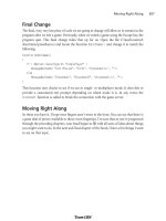
Moving Right Along
In this chapter, we examined how to collect images to use
in applying textures to objects that represent real-world
structures. We saw some of the processing techniques that
we may need to use to prepare our images for use as tex-
tures, like color matching and cropping.
Some of the areas that can be more problematic when
considering textures for structures are scaling the images and preparing them to be "tiled"
if the texture will be used in a repeating fashion. A texture that can be tiled is one whose
opposite edges can be mated together without producing a noticeable seam.
Finally, we explored some of the more common texture patterns and characteristics that
are used in games.
In the next chapter, we will look at terrains, which are often used to provide that touch of
realism in our game worlds. Some of the ideas we've covered in this chapter will certain-
ly be useful in the next chapter as well.
Moving Right Along 363
Figure 11.31 A plastic texture.
Team LRN
Please purchase PDF Split-Merge on www.verypdf.com to remove this watermark.
This page intentionally left blank
Team LRN
Please purchase PDF Split-Merge on www.verypdf.com to remove this watermark.
365
Terrains
chapter 12
M
any games take place exclusively inside buildings or structures, like tunnels.
And many other games involve exclusive outdoor game play. Then there are
some games that have a mix of each.
When your game has an outdoor component, you need to represent the terrain, which in
game terms is the combination of the topography (hilliness, for example) and ground
cover (grass, gravel, sand, and so on). The topography is modeled using a 3D model, and
the ground cover is represented by textures.
In addition to representing the ground, you also need to represent the sky, if you want to
have interesting outdoor game play. Typically, a construct called a skybox is used to repre-
sent all of the sky, from horizon to horizon.
Terrains Explained
To understand terrains in a game development
context, we need to look at the characteristics of
the terrain we want to model. These characteris-
tics will drive our need for the data that defines the
terrain we want to make and therefore will heavi-
ly influence how and where we obtain that data.
Terrain Characteristics
A basic unit of terrain is the tile. Essentially a ter-
rain tile is a collection of polygons that form a
3D model that represents the terrain, as depict-
ed in Figure 12.1.
Figure 12.1 An untextured terrain tile.
Team LRN
Please purchase PDF Split-Merge on www.verypdf.com to remove this watermark.
When we model terrain in a game, there are a number of choices we have to make. We
need to decide the level of terrain fidelity we want to achieve. Another choice is to figure
out the spread of the terrain. Finally, we need to decide what sort of freedom the terrain
embodies. Table 12.1 lists characteristics and the ramifications of each of these choices.
Chapter 12
■
Terrains366
Table 12.1 Terrain Characteristics
Characteristic Description
Fidelity
Terrain fidelity
measures how accurately the terrain reflects real topography found
somewhere in the world—how realistic it is. The realism can be reflected in both the
modeling and the textures. Modeling fidelity can be described as any of the following:
Realistic: Accurate at 1:1 scale in all dimensions with high-resolution textures
representing the terrain cover.
Semirealistic: Accurately scaled, usually to a smaller size. Often the vertical
scale is 1:1 while the horizontal scales are around 1:2. The game
World War II
Online
by Cornered Rat Software has all of Western Europe modeled in this
fashion. The game uses medium-to-low resolution textures to represent
ground cover.
Quasi-Realistic: Not accurately scaled in any dimension, but still attempts to
represent a real location in the world. Usually employs high-resolution ground
cover textures. The scales and textures are chosen to give a sense of the locale
that works well in the game environment. NovaLogic's
Delta Force
series
takes this approach.
Unrealistic: Everything else! Unrealistic terrain is most commonly used to
specifically enhance game play or the backstory of the game.
Spread
Terrain spread
is the degree to which areas of the terrain are unique. Terrain is created in
units called tiles. The spread is related to these tiles in one of three ways:
Infinite: A square terrain region is repeated, or tiled, in all cardinal directions, such
that when the player leaves a region to the west, he enters a new copy of the
same terrain tile from the east. This continues for as long as the player keeps
moving in that one direction.
Finite: The terrain tiles are repeated in all directions, but at some point the
repetition stops.
Untiled: Terrain tiles are not repeated.
Freedom
Terrain freedom
is the measure of how much the player's in-game movements are
restricted by the terrain. Terrain freedom is closely coupled with terrain spread. There are
really only two degrees of terrain freedom:
Closed: Closed terrain limits player movements in all cardinal directions at some
point. With closed terrain, at some point after a player has been moving in a
particular direction, he cannot continue that way, either because there is a virtual
physical barrier or because the program prevents further movement. In any case,
the terrain is usually modeled beyond the barrier only as far as the player can
see. After that—nothing.
Open: Open terrain allows player movement in any direction for as long as the
player wants. Some games will warp the player to the "other side" of the world,
where he will keep crossing terrain tile copies until he returns to the place he started.
Team LRN
Please purchase PDF Split-Merge on www.verypdf.com to remove this watermark.
There are practical considerations that direct our terrain design choices. Many game
engines simply aren't capable of handling the distances involved in large-scale terrains or
the number of objects required to appropriately populate them. Some game genres aren't
suited to open terrains—the player needs to be confined in order to advance the game
story as required.
Terrain Data
When you want to create a high-fidelity terrain model of a real place in the world, you are
going to need to get the data from somewhere. If the area in question is small enough, you
may be able to go out and gather the information yourself if you're handy with a theodo-
lite (a surveyor's tool). You might be able to glean the necessary information from topo-
graphic maps. In either case there is a lot of work involved in the data gathering phase
alone. You will need accurate distance measurements and altitudes, as well as photos of
the ground cover.
But don't despair! There are sources for high-resolution terrain information available on
the Internet. If you go to , the Web portal for the United States
Geological Survey (USGS; part of the U.S. government), you can find a wealth of terrain
data.
The data is available in several forms, but the standard form is the DEM (Digital Elevation
Model). DEM-formatted data files have the .dem file extension. Another format in use is
the DTM (Digital Terrain Model), which uses the .dtm file extension. Finally, a powerful
and complex format called SDTS (Spatial Data Transfer Standard) also exists but is not in
wide use outside of scientific niches. SDTS files are denoted by the .ddf file extension.
In any event, the ground cover information is not included in these various model for-
mats, so you'll need to gather that as well. Again, the USGS comes in handy with its satel-
lite imagery—some of it taken down to a resolution of less than a meter per image pixel.
DEM files provide elevation information for specific coordinates of places on Earth. DEM
files can be converted to a format used by game engines called a height map. We won't go
into detail about how to use DEM data for your game, but you can use several of the
resources listed in the appendixes to locate the data and tools needed.
Terrain Modeling
There are basically two approaches that 3D game engines use to model terrain in a 3D
world. In both cases 3D polygon models represent terrains.
In the external method we include the terrain as just another object in the game world.
This method offers much freedom of manipulation. You can rotate the terrain model,
skew it, and otherwise subject it to all manner of indignities. All 3D engines support this
approach. While flexible, it is usually an inefficient way to render complex large terrains.
Terrain Modeling 367
Team LRN
Please purchase PDF Split-Merge on www.verypdf.com to remove this watermark.
The second approach is the internal method, where terrain is rendered by special code in
the game engine often called a Terrain Manager. Using the Terrain Manager approach
allows game engine programmers to apply specific memory and performance optimiza-
tions to the terrain object, because they can discard unnecessary functions that would be
available to general-purpose objects. Because of this, Terrain Manager terrains can some-
times be made larger and more complex than those created using other approaches.
Most 3D engines, like Torque, that use a Terrain Manager also provide terrain generation,
manipulation, and editing tools that we can use to create our own terrains. Usually
importing height maps is available for terrain generation. Some engines, like Torque, have
built-in Terrain Editors that allow the game developer to directly manipulate terrain poly-
gons, within constraints, to create the desired hills, valleys, mountains, and canyons.
Height Maps
Figure 12.2 depicts a height map. As you can see, it's a grayscale image. The 2D coordi-
nates of the height-map image map directly to surface coordinates in the game world. The
brightness off each of the pixels in the image represents the altitude at that pixel's loca-
tion—the brighter the pixel, the higher the elevation. Usually we use an 8-bit per pixel for-
mat, which means that 256 discrete elevations can be represented.
The concept is an elegant one and not difficult to grasp. If you are familiar with viewing
topographic charts and maps, you'll find that height maps have a familiar flavor to them,
even though the contour lines are missing. One of the deficiencies of height maps is the res-
olution (as you can see in Figure 12.2). To represent a geographic locale that is 1 kilometer
square, a height map that represents 1 square meter as a pixel needs 1,000 pixels per side, for
a total of 1 million pixels—big, but not too large. If I want to increase the terrain area to
cover 16 square kilometers (4 meters per side), then I need to store 16 million pixels. At 8
bits per pixel, that equals about 16MB of data. If we
want to model the terrain for an area that is 10 kilo-
meters per side, we are looking at 100MB of storage!
We can, of course, reduce the terrain resolution—
let's say, have a pixel equal 4 square meters in the
game world. This would chop those 100MB back to
6.25MB. However, that gain is offset by the fact that
our terrain will now be blockier and less realistic.
Figure 12.3 shows a terrain model generated from
the height map shown in Figure 12.2. In this case
MilkShape was used to import the height map and
create the terrain object.
Chapter 12
■
Terrains368
Figure 12.2 A terrain height map.
Team LRN
Please purchase PDF Split-Merge on www.verypdf.com to remove this watermark.
Terrain Cover
In the simplest sense, terrain cover refers to all the
stuff that you find on the ground, including:
■
grass
■
flowers
■
dirt
■
pebbles
■
rocks
■
trash
■
litter
■
pavement
■
concrete
■
moss
■
sand
■
stone
Obviously this is not a comprehensive list, but it does demonstrate the point.
We represent the terrain cover with textures. Our options for creating these textures are
much like those we considered when we created textures for structures in Chapter 11—
and the factors that dictate which way to choose are also similar. It boils down to the ter-
rain characteristics in the game that matter to you.
We can also mix terrain cover textures in adjacent areas to portray a particular locale. It's a
good idea to develop your own library of generic terrain cover for use in various situations.
Figure 12.4 illustrates some of the possible varieties of terrain cover. From left to right in
the top row you can see grass, sand, and an intermixed sand and grass texture. In the bot-
tom row from left to right are dirt, a muddy track, and eroded wet sand.
Tiling
Unless you are going to create specific terrain
cover textures for every square inch of terrain,
you will end up tiling your terrain cover at
some point. All the issues brought up with
tiling in other contexts apply here, such as
matching texture edges to get seamless transi-
tions and ensuring lighting in the textures is
both appropriate and uniform. Additionally,
Terrain Modeling 369
Figure 12.3 A terrain created from a
height map.
Figure 12.4 Some example terrain textures.
Team LRN
Please purchase PDF Split-Merge on www.verypdf.com to remove this watermark.
you should ensure that there are no patterns or marks in the texture that will stand out
too much when the texture is repeated.
In Figure 12.5 you can see a repeating light pattern that tends to overpower the otherwise
pleasing and pastoral scene. (Okay, okay, it would be pastoral if a storm wasn't brewing
beyond the, um…Mountains of Evil in the distance. But besides that…)
The culprit in this case is the grass texture used, which is shown in Figure 12.6.
Notice the area of lighter grass, which is quite noticeably different from the rest of the
image. When repeated over and over across large swaths of terrain, that feature detracts
from the intended overall effect. We can enhance the image to minimize the problem, per-
haps with something like that shown in Figure 12.7.
The result is dramatic and the difference is quite obvious, as you can see in Figure 12.8.
Now, I confess that the texture could be better, but you have to admit that it is light-years
ahead of the first version,
shown in Figures 12.5 and 12.6.
Creating Terrains
Okay, enough talk. Time for
some action—let's create some
terrain. We'll use the Torque
Engine and its internal Terrain
Manager to create the terrain,
and we'll employ the height-
map method using the in-
game Terrain Editor. There is
another method, direct manip-
ulation, that we'll use later in
Chapter 18.
The Height-Map
Method
For this section, you will
need to fire up Paint Shop
Pro. You should be fairly
familiar with the basics, so I
won't hold your hand too
much with respect to PSP
operations.
Chapter 12
■
Terrains370
Figure 12.5 A terrain with tiling artifacts.
Figure 12.6 A texture with
an undesirable feature.
Figure 12.7 A texture
without the undesirable feature.
Team LRN
Please purchase PDF Split-Merge on www.verypdf.com to remove this watermark.
note
The default size for a terrain in
Torque (when the squareSize
property in a MIS mission file
is set to 8) is 65,536 world
units (WU).
One WU in Torque is equal to
one unit in most third-party
map editors. A WU is equiva-
lent to one scaled inch.
1. Start with a drawing of
the contours to create
the height-map image.
If you have a source for
colored contour drawings for a section of land drawn at full scale (1:1), such as shown
in Figure 12.9, get one that suits your needs. If not, you can use the images shown
here, but in their colored format, which you will find
at C:\3DGPAi1\RESOURCES\CH12. Each image has
the same name as the figure number used here.
2. Clip out the portion you want and save it as a PNG
image, as shown in Figure 12.10.
3. Now you need to do a little noodling over scale and
unit numbers.
In Torque each terrain square is made of two terrain
triangles sized at 256 WU by 256 WU; as mentioned
earlier, the default
squareSize
property in a Torque
mission file equals 8 by default. The terrain has
256 of these squares per side for a total of 65,536
world units (inches) per side.
256 WUϫ256 squares=65,536 WU (inches)
If we convert the units, we get 5,641.3 feet, or
1,664.6 meters (1.034 miles, or 1.6646 kilometers).
65,536 inchesϬ12 inches=5,461.33 feet
1 mile=5,280 feet
5,461.33 feetϬ5,280 feet per mile=1.034 miles
1 mile=1,609 meters
1,664.6177 metersϬ1,609 meters per mile=1.034 miles
Creating Terrains 371
Figure 12.8 The terrain with improved tiled texture.
Figure 12.10 Cropped and
resized contour map.
Figure 12.9 Contour map.
Team LRN
Please purchase PDF Split-Merge on www.verypdf.com to remove this watermark.
The value 8 (for
squareSize
) and the value 65,536 (for terrain size) are not acciden-
tal; they are powers of 2. This works nicely with our images as well as the software.
The size for our height-map image must be 256 pixels by 256 pixels. This means
that when the image is stretched to fit our terrain of 65,536 inches by 65,536
inches, each texture pixel (texel) determines the horizontal distance of 256 inches
(or 6.504 meters) of terrain. Because each terrain square is 256 WU, each height-
map texel is used to determine the height of one terrain square.
256 pixelsϫ256 WU (inches)=65,536 WU (inches)
256 inchesϬ39.37 inches per meter=6.5024 meters
6.5024 metersϫ256 pixels=1,664.6177 meters=1.664 kilometers=1.034 miles
4. Based on the preceding calculations, we can get the equivalent area in the image—
crop the image just inside the line box created in the Figure 12.10 drawing repre-
senting 1.034 square miles.
5. Resize the image to 256 by 256 pixels.
6. Save the image as a PNG file to preserve the original colors for the contours.
In a moment you will paint over this contour image using gray color values repre-
senting the heights of the contour lines. In this case the contours range from an
elevation of 410 feet to 485 feet. This information is available from the source of
the contour maps. The grayscale can be any sequence of gray RGB values within
the 256 colors ranging from 0,0,0 (black) to 255,255,255 (white).
7. Establish your scale, keeping in mind that it's best to have some separation between
the incremental values so they can be easily seen as you paint the contours.
Examination reveals that there are 16 elevation increments in the contour range of
410 to 485. Divide the 256 colors for the grayscale range by 16, and you will get the
values in Table 12.2, which starts at the color (0,0,0) and works up.
Now that we have the values, we need to create what Paint Shop Pro calls swatches.
We need to make a different swatch for each increment.
8. Make sure that you have the Materials palette visible in Paint Shop Pro by choos-
ing View, Palettes, Materials and clicking on the Swatches tab in the Materials
frame.
9. Delete any existing swatches by clicking on each one and then clicking on the trash
can icon below the swatches. If you think you can keep track of your custom
swatches and the ones already there, then you can skip this step.
Next we will create a new swatch for our first increment.
1. Click the Create New Swatch button at the bottom of the Swatch frame.
2. Type in a name for your swatch. I suggest you use either the increment number or
the elevation value for the name. You could also use both, as in 1-485 for the top-
most entry from Table 12.2.
Chapter 12
■
Terrains372
Team LRN
Please purchase PDF Split-Merge on www.verypdf.com to remove this watermark.
3. The Color dialog box will appear. Here you type in your RGB values, referring to
Table 12.2 for your numbers. Click OK to close the dialog box.
4. Repeat steps 1, 2, and 3 for each increment in the table.
5. Now fill in your image following the contour lines as shown in Figure 12.11. Use a
combination of the Brush and Fill tools, at your discretion, to complete the task.
Notice that in Figure 12.11 the grayscale value is the same at all the edges. This is
because we want the edges to match when the terrain repeats itself, if it is tiled—
and in this case that's what we will be dealing
with. The edges could be different values; you
would then just match them at the top and bot-
tom or left and right sides.
6. When you have finished the "paint-by-number"
process, convert the image to grayscale by choos-
ing Image, Grayscale.
7. Save your image as a PNG file.
8. Flip the image around its X-axis—this flips the
top with the bottom—by choosing Image, Flip.
You should get an image like that in Figure
12.12. Make sure you save your work.
Creating Terrains 373
Table 12.2 Elevation RGB Values
Elevation RGB Increment
485 240,240,240 1
480 224,224,224 2
475 208,208,208 3
470 192,192,192 4
465 176,176,176 5
460 160,160,160 6
455 144,144,144 7
450 128,128,128 8
445 112,112,112 9
440 96, 96, 96 10
435 80, 80, 80 11
430 64, 64, 64 12
425 48, 48, 48 13
420 32, 32, 32 14
415 16, 16, 16 15
410 0, 0, 0 16
Figure 12.11 Contour map with
grayscale values.
Team LRN
Please purchase PDF Split-Merge on www.verypdf.com to remove this watermark.
Notice the terrace effect in Figure 12.12. If you
import this into Torque as is, you will have a set
of terraced, or stepped, surfaces. If this is what
you want, then you're good to go already. How-
ever, let's go a bit farther.
9. Make a copy of the image you created in step 7 to
work with.
10. Choose Adjust, Blur, Gaussian Blur to smooth out
the edges a bit. Use a radius of four and then save
your changes to this new image as a PNG file. You
should get an image much like the one shown in
Figure 12.13.
tip
It can be more difficult to locate your original contour features after smoothing with Gaussian Blur.
A quick work-around is to try reducing the radius or use the original image unblurred and smooth
the terrain in Torque using the Terrain Editor (covered later).
A more time-consuming technique (but much more accurate and rewarding) is to create the ter-
rain image at a much larger scale and reduce it to 256 by 256. For example, you might try con-
structing the image at around 2,048 by 2,048 or 4,096 by 4,096; this means
much
more painting
time, but after reducing the image size again, the blending information is retained (although
somewhat smoothed) by the resize algorithms. The resulting terrain is much more accurate than
the Gaussian Blur process.
This last height-map image is the one you will work with to create the terrain.
Next, we will import these images into Torque.
11. Place the images in Torque's C:\3DGPAi1\common\editor\heightscripts folder. If
the folder does not already exist, create it.
12. Use the Run fps Demo shortcut to launch
Torque.
13. Run any existing mission to which you'd like to
add this terrain or choose File, New Mission.
14. Press F11 to open the World and Terrain Editor.
15. Choose Window, Terrain Terraform Editor (as
shown in Figure 12.14) to open the
Terrain Terraform Editor.
16. On the right side of the screen, in the General
Settings area (see Figure 12.15), set Min
Terrain Height and Height Range in meters.
Chapter 12
■
Terrains374
Figure 12.13 Blurred height map.
Figure 12.12 Terraced height
map.
Team LRN
Please purchase PDF Split-Merge on www.verypdf.com to remove this watermark.
The maximum elevation in the terrain we are
modeling is to be used for Minimum Terrain
Height (the Minimum Terrain Height box is misla-
beled in the Editor). You will recall that the highest
elevation is 485 feet; this translates to a Minimum
Terrain Height value of approximately 148 meters.
485 feetϬ3.281 feet per meter=147.8208 (148) meters
Height Range represents the distance from our
lowest to highest elevation. The grayscale color val-
ues of our height-map image will be interpolated
between these values. We need to calculate the dif-
ference and multiply that by the ratio of highest
color number divided by total number of grayscale
colors (256) and convert to meters. Clear as mud?
485 feetϪ410 feet=75 feet
240Ϭ256ϫ75 feet=70.3 feet (240 is our highest color number in
Table 12.2)
70.3 feetϬ3.281 feet per meter=21.4 (21) meters
17. Now click the Operation box to roll out the Opera-
tion dialog box, as shown in Figure 12.16.
18. Select Bitmap from this dialog box—this brings
up a bitmap Load File dialog box, as shown in
Figure 12.17.
19. Highlight the image you want translated to a new
terrain and click the Load button. You should find
the height-map image you saved earlier in
C:\3DGPAi1\common\editor\heightscripts, from
Paint Shop Pro.
20. Click the Apply button at the right side of the
menu. You will see the terrain change. To relight
the scene, choose Edit, Relight Scene. There will be
a slight pause in input response while the relight-
ing occurs.
21. In the lower left of the screen the overhead map
view of the terrain will change to show the con-
tours imported from the height-map image.
Notice that this image, as depicted in Figure 12.18,
has the same orientation as the original one before
we flipped it around the X-axis in step 8 of this list.
Creating Terrains 375
Figure 12.14 World Editor
Window menu with Terrain
Terraform Editor checked.
Figure 12.15 Terraform Editor.
Figure 12.16 The Operation
dialog box.
Team LRN
Please purchase PDF Split-Merge on www.verypdf.com to remove this watermark.
The white line in the map shows the
terrain boundary, representing the
extents of your terrain before repeat-
ing. In the main 3D view, a green
translucent box illustrates this bound-
ary, as you can see in Figure 12.19. The
terrain boundary is a fixed dimen-
sion—you can't change it.
Figure 12.20 illustrates where to find
the inner red box that represents the
mission area. You can change the
extents of the mission area boundary by
using the Mission Editor.
22. Choose File, Save As to save your mis-
sion with your own unique name. You
should save your new file in the direc-
tory C:\3DGPAi1\fps\data\missions.
When you save your mission, the terrain data is also
saved as a TER file in the C:\3DGPAi1\fps\data\mis-
sions directory. If you want, you can also import
previously saved TER files rather than re-creating
height maps.
Chapter 12
■
Terrains376
Figure 12.17 The Load File dialog box.
Figure 12.18 The overhead view.
Figure 12.19 The terrain boundary.
Figure 12.20 The mission area.
Team LRN
Please purchase PDF Split-Merge on www.verypdf.com to remove this watermark.
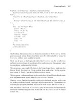
note
Reference to the newly created terrain file is stored in the mission file in a TerrainBlock that needs
to be named "Terrain":
new TerrainBlock(Terrain) {
rotation = "1 0 0 0";
scale = "1 1 1";
detailTexture = "~/data/terrains/details/detail1";
terrainFile = "./myterrain.ter";
squareSize = "8";
locked = "true";
position = "-1024 -1024 0";
};
Creating Terrains 377
Establishing Terrain Sizes
The units displayed in the Mission Editor map (x, y, w, h) represent the (x,y) distance of the upper-left
corner of the mission area (in red) from the image center and the (w,h) width and height of the area
in terrain texture units. Note that the position parameter in the mission file also uses the terrain tex-
ture units to position one terrain repetition.There are 32 repetitions of the terrain textures (don't con-
fuse these with the height-map images) with each terrain texture image being 256 by 256 pixels.
32 repsϫ256 pixels=2,048 texture units
65,536 WUϬ2,048 texture units=32 WU per texel
This information will be useful when creating terrain textures. Convert these values to inches by
multiplying by 32. (The total area represented ranges from Ϫ1,024 to +1,024 when the terrain
squareSize=8 for a total 2,048. And 2,048ϫ32=65,536.)
If your contour area needs to be other than 1.034 miles, you can change the terrain
squareSize.
This will determine the area available before the terrain repeats. As you can see in Table 12.3, you
must adjust the
squareSize parameter in powers of 2.
Table 12.3 Terrain Sizes
Terrain
Texels +/Ϫ, Texels ϫ 32 = WU Feet Miles Meters
SquareSize total
32 +Ϫ4,096=8192 8,192ϫ32=262,144 21,845.33 4.137 6,658.13
16 +Ϫ2,048=4,096 4,096ϫ32=131,072 10,922.66 2.068 3,329.06
8+Ϫ1,024=2,048 2,048ϫ32=65,536 5,461.33 1.034 1,664.53
4+Ϫ512=1,024 1,024ϫ32=32,768 2,730.66 0.517 832.26
2+Ϫ256=512 512ϫ32=16,384 1,365.33 0.258 416.13
Team LRN
Please purchase PDF Split-Merge on www.verypdf.com to remove this watermark.
Changing the terrain
squareSize
in the mission file also affects the control in the Terrain
Editor and terrain material painter; you will have more control at smaller sizes. Be sure to
change the position values of the terrain to correspond to the
worldSize
also. For exam-
ple, if you want more control of the terrain editing, set the
squareSize
to 4 and the posi-
tion to Ϫ512 Ϫ512 0:
new TerrainBlock(Terrain) {
rotation = "1 0 0 0";
scale = "1 1 1";
detailTexture = "~/data/terrains/details/detail1";
terrainFile = "./myterrain.ter";
squareSize = "4";
locked = "true";
position = "-512 -512 0";
};
Applying Terrain Cover
Terrain textures must be PNG format images and must be 256 by 256 pixels in size. These
textures should be placed in a subdirectory under C:\3DGPAi1\fps\data\terrains; they will
also work directly in the terrains folder.
Terrain textures are stretched to 2,048 world units (WU) if the terrain
squareSize
is 8. This
means there are 32 repetitions of a terrain texture across one terrain width or depth (1 ter-
rain rep). This also means there are 8 WU per texture pixel (texel).
65,536 WUϬ32 texture reps=2,048 WU per texture rep
2,048 WUϬ256 pixels=8 WU per texel
If the terrain
squareSize
is set to 4 in the mission file, there will still be 32 terrain texture
repetitions, but each repetition will only cover 1,024 WU of the terrain.
And although not a requirement, terrain cover tex-
tures will look best when they are created to be
tiled, as discussed earlier; opposite edges should
match so that when they are tiled you won't be able
to see the edges. The images in Figure 12.21 and
12.22 are test textures that are 256 by 256 pixels.
The checkerboard pattern in Figure 12.21 has each
white or black section sized at 128 by 128 pixels.
The grid texture in Figure 12.22 has white lines
every 32 pixels and red lines at 128 pixels. You can
use these images to calculate the total terrain size
with respect to the dimensions of objects created in
Chapter 12
■
Terrains378
Figure 12.21 Checkerboard texture.
Team LRN
Please purchase PDF Split-Merge on www.verypdf.com to remove this watermark.
a map editor as well as to calculate the terrain square size with respect to terrain textures.
In addition, you can use the image in Figure 12.22 to create sightlines when manually
adjusting terrain heights.
To paint our terrain cover:
1. Place these images in a subdirectory under C:\3DGPAi1\fps\data\terrains.
2. Use the Run fps Demo shortcut to launch Torque.
3. Select the mission you created in the previous section.
4. Press the F8 function key to switch to "fly" mode.
5. Fly up above the terrain a bit using the arrow
keys to move and the mouse to aim and look
down. You can use F7 to switch out of fly
mode when you want.
6. Press F11 to open the World and Terrain
Editor.
7. Choose Window, Terrain Texture Painter, as
shown in Figure 12.23.
You will now see the Material Selection dialog box
(as shown in Figure 12.24) to the right. You can
highlight the material you want to paint with or
change or add new textures here.
8. To add a new material, click an Add or Change button
and you will get a new texture image Load File dialog
box, as shown in Figure 12.25.
9. Highlight the image you want and click the Load but-
ton. That image is now in your selection set.
10. From the Action pull-down menu, make sure Paint
Material is checked.
11. Now go up to the
Brush pull-down menu
and select your desired
brush size.
Remember that we are using
the default terrain
squareSize
set to 8. Table 12.4 lists
the area of the terrain that
is influenced based on
brush size.
Creating Terrains 379
Figure 12.22 Grid texture.
Figure 12.23 World Editor
Window menu with Terrain
Texture Painter checked.
Figure 12.24 Material
Selection dialog box.
Team LRN
Please purchase PDF Split-Merge on www.verypdf.com to remove this watermark.
Figure 12.26 depicts a texture applied with the
brush size set to 1, and Figure 12.27 shows the
corresponding terrain grid.
You can see the 32 by 32 texel influence area for
one brush that corresponds to 256 WU for the ter-
rain squares shown in the grid view.
So take your trusty Terrain Paint Brush and go
nuts!
Moving Right Along
So, now we understand why terrains need to be
modeled, and what our options are for obtaining
real-world terrain data. If we aren't modeling a real
location, we've seen how we can create our own
imaginary terrain using Paint Shop Pro, so that we
can satisfy the needs of our game. We also looked
at terrain cover, and how to create images for use
as terrain cover.
We also learned about some of the visual anom-
alies, like terrain tiling seams that might make our
terrains less pleasing, and how we can go about fix-
ing those issues.
Earlier in the chapter, Figure 12.8 showed an exam-
ple of a finished terrain, with some hills in the distance, and terrain cover applied.
In the next chapter, we'll learn a pair of new tools, MilkShape and UV Mapper.
Chapter 12
■
Terrains380
Figure 12.25 Image Load File dialog box.
Table 12.4 Brush Sizes
World Units
(texels ϫ
Brush Size Texels squareSize)
11ϫ32=32 32ϫ8=256
33ϫ32=96 96ϫ8=768
55ϫ32=160 160ϫ8=1,280
99ϫ32=288 288ϫ8=2,304
15 15ϫ32=480 480ϫ8=3,840
25 25ϫ32=800 800ϫ8=6,400
Figure 12.27 Terrain Grid with a
brush size set to 1.
Figure 12.26 Painting Terrain with a
brush size set to 1.
Team LRN
Please purchase PDF Split-Merge on www.verypdf.com to remove this watermark.
381
Introduction to
Modeling with
MilkShape
chapter 13
I
n this and the following chapters, we will be delving into the world of low-poly model-
ing. We'll talk about techniques and methods that can be applied to other tools, such as
the expensive 3D Max or Maya, but the practical focus will be geared toward using
MilkShape, UVMapper, and other low-cost tools that are included on the enclosed CD.
MilkShape 3D
In Chapter 9 we created a skin for a simple soup can—remember that? Well, in this chap-
ter we're going to create the model and skin it with the texture you created earlier, only
this time we will go beyond just the simple soup can. But first, let's start at the beginning
and learn a bit about MilkShape.
MilkShape 3D is a great low-cost low-poly 3D modeling tool created by a fellow named
Mete Ciragan. Like most successful shareware applications, it has evolved over the years,
as Mete added features requested by his user community. He also added the capability for
users to create their own plug-ins to provide additional features and import-export filters.
MilkShape is not as complex as the more expensive tools, but that does not in any way
imply that it is not a capable program, especially in the low-poly world that computer
games inhabit. In fact, the stripped-down nature of MilkShape certainly makes it easier to
learn than most of the "big boys."
Installing MilkShape 3D
If you want to install only MilkShape 3D from the enclosed CD, do the following:
1. Browse to your CD in the \MS3D directory. (MS3D is the abbreviated form for
MilkShape 3D. You'll encounter it a fair bit.)
Team LRN
Please purchase PDF Split-Merge on www.verypdf.com to remove this watermark.