Tài liệu 3D Game Programming All in One- P17 ppt
Bạn đang xem bản rút gọn của tài liệu. Xem và tải ngay bản đầy đủ của tài liệu tại đây (778.75 KB, 30 trang )
1. Using Windows Explorer, browse your way to C:\3DGPAi1\resources\tools and
launch UVMapper.exe.
2. Maximize the window when it opens.
3. Find the file you exported, C:\3DGPAi1\resources\ch9\mynewcan.obj, and open it.
4. You will see an alert, listing some statistics about the object. Click OK.
5. You will see a bunch of triangles fill your window. Ignore them for the moment.
6. Choose Edit, New UV Map, Cylindrical Cap. You will get a Cylindrical Cap Map-
ping dialog box.
7. Click OK. You will then get a layout of the can's triangles (like that in Figure 13.7),
with a rectangular block of triangles across the middle and a circle of triangles at
both top and bottom.
8. Choose File, Save Model. The OBJ Export Options dialog box then appears.
9. Set the options boxes as shown in Table 13.1 and click OK.
10. Replace the OBJ file C:\3DGPAi1\resources\ch9\mynewcan.obj by saving over it.
11. Choose File, Save Texture Map. The BMP Export Options dialog box appears.
12. Set the options to the values shown in Table 13.2.
13. Save to the file name C:\3DGPAi1\resources\ch9\mynewcan.bmp. This is the texture
map, or UV mapping template, for your can.
14. Switch back to MilkShape.
15. Choose the Groups tab and select the can group.
16. Click the Delete button. You will replace this object with the one you exported
from UVMapper.
17. Choose File, Import,
Wavefront Obj and
import the
mynewcan.obj file you
saved from UVMapper.
18. On the Groups tab,
locate your new object
(mynewcan.obj), select it,
and rename it if you like.
19. With the new object
selected, choose the
Materials tab.
20. Choose the label mater-
ial and then click Assign.
MilkShape 3D 387
Figure 13.7 Unwrapping the can in UVMapper.
Team LRN
Please purchase PDF Split-Merge on www.verypdf.com to remove this watermark.
21. Your texture should appear on the can in the 3D view, wrapped correctly.
22. If no texture appears, click in the 3D window to force an update.
23. If there is still no texture, make sure that you have the 3D window still set to Tex-
tured, by right-clicking in the 3D window and checking the menu.
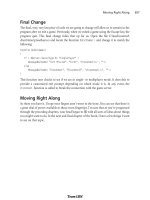
Enhancing the Soup Can Model
Have a seat and stew on that for a while. When you are done, we'll carry on and start ham-
mering at the soup can and improve the model.
How about we open the can up? The can model has a top and a bottom. We want to leave
the bottom where it is and flip the top lid up.
First we need to separate the lid from the can.
1. Choose the Model tab and click Select.
Chapter 13
■
Introduction to Modeling with MilkShape388
Table 13.1 UVMapper OBJ Export Options Values
Value Option
clear Export As Single Group
set Export Normals
set Export UV Coordinates
clear Flip Texture (UV) Coordinates Vertically
clear Flip Texture (UV) Coordinates Horizontally
clear Reverse Winding Order
clear Invert Normals
clear Swap Coordinates Y and Z
set Export Materials
set Export UVMapper Regions
clear Export Using Rotation Settings
clear Don't Export Linefeeds (Mac compatible)
clear Don't Compress Texture Coordinates
Table 13.2 UVMapper BMP Export Options Values
Value Option
512 Bitmap Size—Width
512 Bitmap Size—Height
clear Flip Texture Map Vertically
clear Flip Texture Map Horizontally
clear Exclude Hidden Facets
Team LRN
Please purchase PDF Split-Merge on www.verypdf.com to remove this watermark.
2. Click Vertex and select all the vertices at the bottom of the can, as shown in Figure
13.8. Use either the Side view or the Front view.
3. Choose Edit, Hide Selection. The dots of the vertices will disappear. This means
that none of the vertices for the bottom face are selectable.
4. Now click Face. Make sure that By Vertex is selected.
5. In the Top view, select the vertex in the center of the can, as in Figure 13.9. Because
you had hidden the bottom vertices, only the single center vertex for the top of the can
has been selected. And because you are actually selecting faces by vertex, then all the
top lid faces—and only those
faces—have been selected.
6. In the Groups tab, click
Regroup. This will create a
new mesh with only the faces
from the top of the can. The
mesh will be named
"Regroup01". Rename this
mesh to "lid" in the same
manner that you did earlier
when you renamed the cylin-
der mesh to "can".
7. Switch back to the Model
tab. Your lid mesh should
still be selected.
8. Click the Move button, and
then click and drag in the
Side view to move the lid up
and to one side from the
rest of the can.
9. Click the Rotate button, and
then click and drag in the
side window to rotate the lid
as if you were bending the
lid back (see Figure 13.10).
10. If necessary, repeat step 8 to
position the lid properly.
You might have to adjust it
in one of the other views,
depending on how you ini-
tially moved the lid.
MilkShape 3D 389
Figure 13.8 Selecting the bottom vertices.
Figure 13.9 Selecting the center vertex.
Team LRN
Please purchase PDF Split-Merge on www.verypdf.com to remove this watermark.
11. Choose the Groups tab and
click Regroup. The lid faces
will now be part of their own
group.
12. Choose Edit, Duplicate Selec-
tion. Another copy of the lid
will be made in exactly the
same location as the original.
13. Select Face, Reverse Vertex
Order. This will invert the
normals of the lid's faces,
making it viewable from the
other direction. You will
recall that the normal of a
face is, in the simplest terms,
the direction that a face is
facing.
14. On the Groups tab, add the original lid to your selection by clicking on the first lid
group.
15. Select Vertex, Weld Together. Now the original lid is viewable from one side, and
the copy is viewable from the other. They now share the exact same vertices.
If you rotate your can in the 3D view, you'll see that your lid now has the lid part
of the skin on both sides. You'll also notice that the inside of the can is black. This
is because no faces are normalized to the interior, just as the lid at first did not
have any faces normalized on the side.
tip
You may be wondering why you didn't have to assign a material to the new faces you created with
the Duplicate command. What happened is that when you grouped the original faces and the new
faces together, the material that was assigned to the original lid faces were automatically assigned to
the new group.
16. Repeat the above steps but this time create a set of faces for the can body that are
normalized to the interior instead of the exterior, and then group them together.
You can use your UV mapping and Paint Shop Pro skills to create a more realistic
metallic interior to the can, instead of just repeating the exterior skin on the inside.
17. Save your work—you never know when a nice can of soup may be needed for dip-
ping your towel in!
Chapter 13
■
Introduction to Modeling with MilkShape390
Figure 13.10 The can with lid opened.
Team LRN
Please purchase PDF Split-Merge on www.verypdf.com to remove this watermark.
So, here we are. You've made a model of an object, using a couple of shape primitives. And
you've learned how to make double-sided textures, rotate and move meshes (or groups),
and assign skins. Feel free to explore your new capabilities. Poke around and try out the
other primitives.
Menus
MilkShape can perform many more features and operations than what we've just gone
over. In later chapters you'll learn how to make more difficult and challenging shapes, like
player-characters, vehicles, and weapons. In this chapter we'll take a look at the program
itself in more detail.
Most but not all of the menus have shortcuts assigned to the keys. Typically, the ones that
are used the most do have shortcuts. If you want to add your own shortcut, you can use a
plug-in to do that. We'll cover that when we discuss the Tools menu.
File
As in most Windows pro-
grams, operations in the
File menu (see Figure
13.11) relate either to the
creation and saving of files
or to making global alter-
ations to the current file's
properties or contents. See
Table 13.3 for more detail.
Edit
The MilkShape Edit menu (see Figure 13.12) contains
commands that assist the user when modifying models. It
does not have Cut, Copy, or Paste but does offer com-
mands in a similar vein for duplicating, hiding, and
selecting objects. See Table 13.4 for more detail.
Vertex
You can perform a number of operations on vertices in a
model. They are available through the Vertex menu (see
Figure 13.13). In most cases you will need to ensure that
you've selected only vertices in a model or at least have the
selection mode set to Vertex. See Table 13.5 for more detail.
MilkShape 3D 391
Figure 13.11 The File menu.
Figure 13.12 The Edit menu.
Figure 13.13 The Vertex menu.
Team LRN
Please purchase PDF Split-Merge on www.verypdf.com to remove this watermark.
Chapter 13
■
Introduction to Modeling with MilkShape392
Table 13.3 MilkShape File Menu
Command Description
New Creates a new blank workspace. If the current workspace is not empty, then
the user is prompted to save changes or continue without saving. Only one
workspace can be open at a time.
Open Opens an existing MS3D formatted file using the standard Open dialog box.
Save Saves the current workspace as an MS3D file, providing that the current
workspace has a name. If the workspace is unnamed, then the command will
behave like Save As.
Save As Requires the user to specify a new file name under which to save the
workspace contents.
Merge Merges together two MS3D documents: the current workspace and another
workspace selected from file.
Import Presents a submenu of file import plug-ins. This command works like the Open
command, once an import plug-in is selected, except that some plug-ins offer
import options in a user dialog box.
Export Presents a submenu of file export plug-ins. This command works like the Open
command, once an import plug-in is selected, except that some plug-ins offer
additional export-specific options in a user dialog box.
Preferences Presents the Preferences dialog box. This allows the user to set definable global
application attributes and behaviors.
Exit Exits the MilkShape program. The user is prompted to save changes if there are
any that haven't been saved.
Table 13.4 MilkShape Edit Menu
Command Description
Undo The workspace is reverted back to the state it was in before the last user
operation.
Redo The workspace is reverted back to the state it was in before the Undo
operation.
Duplicate Selection All selected objects are duplicated in place. This command selects the new
duplicates and deselects the previously selected objects.
Delete Selection The currently selected objects are deleted.
Delete All All objects in the workspace regardless of their selection state are deleted.
Select All All objects in the workspace are selected.
Select None All objects in the workspace are deselected.
Select Invert All objects that were selected are deselected, and all unselected objects are
selected.
Hide Selection The selected object is hidden from view. This operation can also be performed
on groups using the Groups tab in the toolbox.
Unhide All All objects in the workspace are shown.
Team LRN
Please purchase PDF Split-Merge on www.verypdf.com to remove this watermark.
Face
The Face menu (see Figure 13.14) provides com-
mands for manipulating triangles and faces in the
workspace. See Table 13.6 for more detail.
MilkShape 3D 393
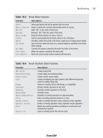
Table 13.5 MilkShape Vertex Menu
Command Description
Snap Together Snaps all the selected vertices together. The middle point between all
selected vertices becomes the new location for the vertices.
Snap To Grid Moves all selected vertices to be in line with the smallest grid X, Y, and Z
position (to see the smallest grid positions, zoom all the way in). The grid
size can be changed using the File, Preferences menu.
Weld Together Creates one vertex at a precise point where several vertices exist. Only
selected vertices are welded together. This is the way you would join a
seam of two or more abutting faces.
Unweld Splits each selected vertex into multiple vertices. The number of vertices
created depends on the number of faces the original individual vertices
were bound to. For example, a vertex with three faces attached will be
split into three vertices.
Unweld Radial Is the same as Unweld but will also shift the unwelded vertices away from
each other in a circular pattern. The vertices will move from the origin at
which they were unwelded by half the distance from the origin to the
nearest edge.
Divide Edge Divides a face between two selected vertices into two faces. The procedure
will only work with two vertices selected. This has no effect on vertices
without any faces in common.
Flatten Presents a submenu for the user to align all selected vertices to the same
point on the X, Y, or Z plane. This is similar to Snap Together but it works
on only one axis instead of all three.
Mirror Front < > Back Mirrors, or flips, the currently selected object along the Z-axis.
Mirror Left < > Right Mirrors, or flips, the currently selected object along the X-axis.
Mirror Top < > Bottom Mirrors, or flips, the currently selected object along the Y-axis.
Spherify Calculates a bounding sphere and attempts to place the selected vertices
on the surface of the sphere. It can be constrained in all three dimensions,
and the bounds can be manually set.
Manual Edit Allows the exact placement of one selected vertex with floating point
accuracy in the X, Y, and Z planes.
Figure 13.14 The Face menu.
Team LRN
Please purchase PDF Split-Merge on www.verypdf.com to remove this watermark.
Animate
The Animate menu (see Figure 13.15) is used to manip-
ulate animation frames in the model via the Keyframer.
See Table 13.7 for more detail.
Chapter 13
■
Introduction to Modeling with MilkShape394
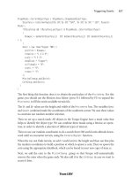
Table 13.6 MilkShape Face Menu
Command Description
Reverse Vertex Order Changes the order of the vertex winding, which changes (negates) the
normal of the face. This will turn a face inside or outside depending on its
current vertex order. Counterclockwise vertex winding creates an outward
face on an object.
Subdivide 3 Divides each selected face by three, creating three faces out of one.
Subdivide 4 Divides each selected face by four, creating four faces out of one.
Turn Edge Is performed on two triangles with a common edge. The common edge is
removed, and a new edge is created between the two vertices (one from
each triangle) that weren't previously joined by an edge.
Face To Front Is used on selected faces to change all vertex orders to counterclockwise,
outward-facing vertex ordering, or
winding
.
Smooth All Is used to smooth all faces after construction of parts of a model.
Figure 13.15 The Animate menu.
Table 13.7 MilkShape Animate Menu
Command Description
Operate On Selected Joints Only When this menu item is toggled on (checked), then only the joints
that are currently selected will have their pose data stored for the
current keyframe.
Set Keyframe This stores the pose of the skeleton to the current keyframe
(whichever keyframe that's in the keyframe number box).
Delete Keyframe This removes the stored skeleton pose from the current keyframe.
Copy Keyframes This copies the skeleton pose from the current keyframe. In order for
the copy action to perform correctly, the user must first select the
skeleton in the keyframe to be copied from.
Paste Keyframes This pastes the copied skeleton pose to the current keyframe. After
the keyframe has been pasted, you need to immediately set the
keyframe in order to preserve the skeleton pose.
Remove All Keyframes This removes all stored skeleton poses at all keyframes in the
animation timeline. This is effectively the same as deleting the
animation.
Team LRN
Please purchase PDF Split-Merge on www.verypdf.com to remove this watermark.
Tools
The Tools menu (see Figure 13.16) provides access to both
built-in tools and user plug-in tools. The functions avail-
able are not the same as those available in the toolbox.
This is a potential source of confusion. See Table 13.8 for
more detail about the Tools menu.
MilkShape 3D 395
Figure 13.16 The Tools menu.
Table 13.8 MilkShape Tools Menu
Command Description
Half-Life This command contains several options used to create and save Half-Life models.
Quake III Arena This command saves a Quake III control file to the directory you specify in the
save window.
Unreal Tournament This command contains options for creating male and female skeletons using
the default Unreal Tournament skeleton configurations.
Decompile Genesis- This command allows you to decompile an ACT model used by the Genesis 3D
3D ACT engine.
Compile Quake1 MDL This option will compile a Quake1 MDL file, used in the Quake 1 engine.
Convert Old MS3D This command converts a file from an old version of the MilkShape 3D file File
File Format format. The command can be used to change files created with MilkShape 3D
versions 1.4.0 and earlier.
Show Model Statistics Brings up a statistics window showing useful statistics, such as the number of
faces and vertices in the workspace.
Plug-Ins The list of plug-ins available is user-configurable using the Shortcut and Plug-
In Manager. Not all plug-ins are distributed with MilkShape. See the
MilkShape sidebar for descriptions of currently available plug-ins. To get the
most up-to-date information about plug-ins, visit chUmbaLum sOft's Web site:
/>Team LRN
Please purchase PDF Split-Merge on www.verypdf.com to remove this watermark.
Chapter 13
■
Introduction to Modeling with MilkShape396
MilkShape Plug-Ins
There is quite a large list of MilkShape plug-ins that extend MilkShape's capabilities. For informa-
tion about where to find them to download, tutorials about how to use them, and the names of
the individual creators, see Appendix B, "Game Development Resources on the Internet." The plug-
ins that were known at the time of this writing are listed; some plug-ins are import or export fil-
ters for different file formats and aren't included here, except for the Torque DTS Exporter, because
we use it in this book (the Wavefront OBJ Importer and Exporter are built into MilkShape).
■
ms2DTSExporter. This plug-in exports models, animations, and materials to DTS model
format for use with the Torque Engine. This plug-in appears in the File, Export menu.
■
msSelectionEditor. This plug-in edits the selection from a 3D view. There are a lot of
options and you can read some detailed information about it here.
■
msTimer. This plug-in lets you time how long you've been working on a certain model.
■
msEdgeExtrude. This plug-in lets you extrude edges in addition to faces.
■
msJointTool. This plug-in allows you to add joints in the middle of the hierarchy, unlink a
joint from a hierarchy, and assign vertices to the closest joint (some kind of "Assign Mesh
to Skeleton" tool).
■
msSnap. This plug-in snaps not only to 1.0, it also snaps joints.
■
msToolArray. This plug-in duplicates objects and then places the duplicates in 3D space
according to user specifications.
■
msVertexPlane. This plug-in is similar to the Vertex, Flatten command, except that it
snaps selected vertices to a plane instead of a single point.
■
msToolFatBoy. This plug-in will make your model fatter or thinner. This is useful for
tweaking player and monster characters.
■
msOperationMirrorAll. This plug-in will mirror everything about your model over the
selected plane: bones, mesh, animation—everything.
■
msToolReverseAnimation. This plug-in will reverse the order of the keyframes in what-
ever animation you have loaded.
■
msToolScaleAll. This plug-in applies scale to all objects in the workspace at once.
■
msSelPolyCount. This plug-in shows the selected polygon, vertex, and unique vertex
counts, as well as how many polygons there are per group.
■
msBridge. This plug-in creates a mesh connecting to previously independent meshes or
groups.
■
msTerGen. This plug-in can generate random terrains or import a bitmap file to use as a
height map.
■
msTextGen. This plug-in generates 3D objects in the form of text.
■
msModelInfo. This plug-in provides more detailed information about a model than the
Show Model Statistics command.
Team LRN
Please purchase PDF Split-Merge on www.verypdf.com to remove this watermark.
Window
The Window menu (see Figure 13.17) provides commands
that determine what information is available in the
MilkShape window and how it is displayed. See Table 13.9
for more detail.
MilkShape 3D 397
■
msTileTextureMapper. This plug-in generates texture coordinates to geometry for tile
textures (also known as
seamless textures
).
■
msLathe. This plug-in takes flat geometry and turns it around the X-axis to build a 3D
model.
You can install plug-ins by simply copying them to the MilkShape directory and then launching
MilkShape. They will then appear under the Tools menu beneath Show Model Statistics.
Figure 13.17 The Window
menu.
Table 13.9 MilkShape Window Menu
Command Description
Viewports This command presents a submenu that allows you to pick an alternative
viewport layout. The four-pane layout with three 2D views and one
Perspective view is the default.
Control Panel This command allows the user to set whether the toolbox frames appear
on the left or right of the main window. The right side is the default.
Texture Coordinate Editor This is for adjusting where textures appear on the model. Although useful,
it is not as powerful or flexible as using a dedicated UV Unwrapping or
Mapping tool like UVMapper.
Show Message Window This option shows a script output window that holds the results of
compiling various types of models for specific games.
Show Viewport Caption This command shows details about the viewport it appears above. From
left to right, the details are the view, the field of view, the near clipping
plane, and the far clipping plane.
Show Keyframer The Keyframer is the animation box along the bottom of the main
window. It is used to create keyframe positions of bones and joints in a
skeleton for animation.
Team LRN
Please purchase PDF Split-Merge on www.verypdf.com to remove this watermark.
The Toolbox
Way back near the start of this chapter, in Figure 13.2, is a depiction of the contents of the
various tabs in the toolbox. In this section here we will dig deeper into the capabilities in
those tabs. Table 13.10 provides a brief summary of each toolbox tab's functions.
You should understand that, in general, when using the functions in the toolbox, we will
first have to select some object via one of the views and then operate on it using one of
the toolbox commands. This sort of noun-verb operation mode requires us to make sure
we have the appropriate objects selected before every action we take.
The Model Tab
The Model tab (see Figure 13.18) contains the tools necessary to
create and modify the basic shape primitives: vertices, faces, cylin-
ders, spheres, and cubes (boxes, as MilkShape calls them). Table
13.11 shows the functions of the Model tab's buttons.
Chapter 13
■
Introduction to Modeling with MilkShape398
Table 13.10 MilkShape Toolbox Summary
Tab Purpose
Model This is used for the placement of vertices and shape primitives, as well as for the
construction of polygons and skeletons.
Groups This contains commands used to group vertices and polygons. Groups can also be
created from existing polygons.
Materials This deals with the creation of materials, including textures from file, ready to be
assigned to groups.
Joints This contains tools for manipulating and managing skeleton joints.
Figure 13.18 The
Model tab.
Team LRN
Please purchase PDF Split-Merge on www.verypdf.com to remove this watermark.
MilkShape 3D 399
Table 13.11 Model Tab Functionality
Button Description
Select This tool puts the program into select mode so that the user can select any object
or collection of objects on one of the wire-frame views. Once you are in select
mode, you can specify one of four different selection target types: vertex, face,
group, or joint. You also have two optional settings: ignore backfaces and by
vertex (which is only available in face selection mode).
Move This tool permits you to move any selected objects by clicking in the appropriate
wire-frame view and dragging the cursor. You can also specify discrete movement
by entering numbers in the Move Options boxes at the bottom.
Rotate This tool permits you to move and rotate any selected objects around a single axis
by clicking in the appropriate wire-frame view and dragging the cursor up or
down. You can also specify discrete rotations and multiple axes rotations by
entering numbers in the Rotate Options boxes at the bottom.
Scale With this tool you can change the size of any selected objects along one of two
available axes in each view by clicking in the appropriate wire-frame view and
dragging the cursor up, down, left, or right. You can also specify discrete scaling and
multiple axes scaling by entering numbers in the Scale Options boxes at the bottom.
Vertex Use this tool to place individual vertices, one at a time, in a wire-frame view. In
each different view, the vertex will be placed at the zero axis position for
whichever axis is not presented in the view. This tool has no options.
Face With this tool you can connect individual vertices to create a face, one vertex at a
time, with three vertices defining a face. The Threshold option specifies how close
to a vertex you need to click to add it to the current face you are building. As you
build the face, select the vertices in a counterclockwise direction to create an
outward normalized face.
Sphere This tool is a shape primitive tool. To create a sphere, simply click and drag the
cursor in a wire-frame view. With the Sphere options you can specify the number
of slices (like the slices in a pie) or stacks (like a stack of pancakes) that make up
your sphere.
GeoSphere Use this tool to create more realistic spheres using a different program technique.
You use the tool the same way as the Sphere tool, but you can only specify the
complexity of the sphere using the Depth option.
Box Use this tool to create cubes. Just click in a wire-frame view and drag until it has
reached the size you want.
Cylinder Use this tool the same way as you use the Sphere tool, even including the
specification of stacks and slices.
Extrude This tool operates only on the faces. If you have two faces aligned to create a
flat surface, like a piece of cardboard, you would use this tool to extend the
surface in a specific direction to create a box. Just click the mouse and drag to
perform the extrusion. Using the Extrude options you can specify which directions
to do the extruding in—normally you would use only one direction at a time. The
Smoothing option tells the program to smooth shade the polygons as it draws the
extruded shape.
continued
Team LRN
Please purchase PDF Split-Merge on www.verypdf.com to remove this watermark.
The Groups Tab
You will often want, or need, to organize your model faces into
groupings that make either visual or logical sense. Whether you
organize them as meshes that make visual sense or simply as logi-
cal groups, you do this with the Groups tab, shown in Figure 13.19.
The Torque DTS Exporter uses special groups with the name colli-
sion to define collision meshes. Table 13.12 presents the functions
available from the Groups tab.
The Materials Tab
With the Materials tab (see Figure 13.20),
you can define the textures that will be
used to skin your model, as well as what
characteristics they will have when dis-
played. Special materials are also used to
define certain model characteristics to the
Torque DTS Exporter. Table 13.13 explains
the functions of the Materials tab.
Chapter 13
■
Introduction to Modeling with MilkShape400
Joint This tool places special joint objects. It works the same as the Vertex tool,
except that if an existing joint is already selected when you make the new
joint, the new joint will be attached to the previous one by a bone. If the
Show Skeleton option is turned on in the Joint tab, the bone will be visible
in yellow.
Redraw All Viewports If you have this option turned on, then every time you perform one of the
tool operations, the views in all the viewports will be redrawn to reflect
your changes.
Auto Tool If you have this option turned on, then the program will alternate between
any tool and the Select tool each time you finish an operation. This option is
handy for tweaking and repetitive adjustment techniques.
Figure 13.19 The
Groups tab.
Figure 13.20 The
Materials tab.
Team LRN
Please purchase PDF Split-Merge on www.verypdf.com to remove this watermark.
MilkShape 3D 401
Table 13.12 Groups Tab Functionality
Button Description
Group Selector Box This is the white area at the top. It contains the names of the
groups, one group per line. You always need to choose a group from
this box before performing any group operations.
Select When you use this tool, the currently chosen group in the list will
become selected in the wire-frame views—that is, it will become
drawn in red. Each time you choose a different group and click the
Select tool, that group gets added to each view's selection.
Hide With this tool you can make the chosen group's faces and vertices
become invisible. This is useful for uncluttering a view or to ensure
that you don't select the wrong parts for another operation.
Delete Use this tool to permanently remove a group from the model.
Regroup With this tool you create new groupings from whatever model
elements are selected (shown in red) in the views. Any elements that
already belong to other groups are removed from those groups and
added to the new group.
Rename Choose a group, type a new name in the Rename box, and then click
the Rename tool. Bingo! The group now has a new name.
Smoothing Groups Select Pressing this key and then one of the Smoothing Group numbers
selects the polygons assigned to that Smoothing Group. Smoothing
Groups can only be selected on the numbers that have been
assigned.
Smoothing Groups Assign When you have a group of polygons selected you can press this
button and then one of the Smoothing Group numbers to assign all
selected polygons to a Smoothing Group. Additional groups of
polygons can be added to the same group without overwriting the
previous contents of the Smoothing Group.
Smoothing Group Numbers These numbers act as a storage bank for groups of polygons. They
can have polygons assigned to them and selected from. If the Auto
Smooth check box is selected, assigning groups of polygons to a
Smoothing Group number will smooth shade them (Smooth Shaded
shading has to be enabled to view the effect of this—right-click the
3D Perspective view and click Smooth Shaded from the pop-up
menu).
Smoothing Group Clear All This button removes the assigned Smoothing Groups from the
Smoothing Group numbers. The polygons will remain smooth
shaded, but they will no longer be in the same Smoothing Group.
Smoothing Group Auto Smooth When assigning Smoothing Groups, ensure this is checked if you
wish the selected polygons to be smooth shaded.
Team LRN
Please purchase PDF Split-Merge on www.verypdf.com to remove this watermark.
Chapter 13
■
Introduction to Modeling with MilkShape402
Table 13.13 Materials Tab Functionality
Item Description
Material Selector Box This is the white area at the top. It contains the names of the
materials, one material per line. You always need to choose a material
from this box before performing any material operations.
Material Preview The currently chosen material is displayed, mapped onto a sphere. You
can click and drag the sphere with the mouse to view hidden parts of
the material map.
Ambient Use this tool to get a color picker window for setting the ambient light
of the environment the material is in. This attribute affects the color
and the intensity of the color that the material reflects.
Diffuse Use this tool to get a color picker window for setting the light that the
material will directly reflect. This attribute has the most influence over
the color of the material.
Specular & Specular Slider Use this tool to set the specular highlight of the material. Basically,
selecting a bright color will create a highlight on the material of the
color chosen. Moving the slider below it changes the focus of the
highlight. The highlight can range from appearing as a small spot to
appearing as if the object is immersed in incandescent light.
Emissive Use this tool to get a color picker window for setting the color and
intensity of the light that the material emits. This attribute will appear
as a glow around the material.
Transparency Slider This slider adjusts the amount of transparency that an alphamap
applies to a texture and the faces that the texture is assigned to. You
must click Assign or click in the viewport to update the model to
reflect your changes.
Texture Browse Button Use this tool to select a texture to apply to the material. Pressing it
will reveal a Windows Explorer browse box from which image files can
be selected. The None button beside this button removes the texture
file from the material.
Alphamap Browse Button Use this tool to apply an alphamap to the material. A black-and-white
image can be used to remove areas of texture where there may be
holes. Black is fully occluded and white is fully visible; it is possible to
use variations of gray to achieve semitransparency. The None button
beside this button removes the alphamap file from the material.
New The New button, when pressed, will create a new blank material with
default attributes, no texture or alphamap files, and a default name.
Delete To delete a material, choose it in the Material Selector, and then click
the Delete button. This literally removes the material from the
workspace, so use this wisely.
Rename Button & Box To rename a material, choose it in the Material Selector box, type the
desired name in the box next to the Rename button, and then click the
Rename button.
Assign Use this tool to assign the chosen material in the Material Selector box
to the selected group.
Team LRN
Please purchase PDF Split-Merge on www.verypdf.com to remove this watermark.
The Joints Tab
Using the Joints tab (see Figure 13.21), you can specify the joints for
skeletons, which are used in animations. Joints are also used as sub-
stitutes for the concepts of special nodes that are used by the Torque
DTS Exporter. Table 13.14 describes the Joints tab functions.
The Keyframer
The Keyframer (see Figure 13.22) is a special tool used for defin-
ing animations for your model. With it, you can save skeletal posi-
tions in a model. You then produce animation by storing several
keyframes to the Keyframer and playing them back. There is a set
of controls for managing the playback. Typically, only frames
where changes take place need to be set by the user; hence the
term keyframe—they are key to the animation. MilkShape 3D will fill in the pose or posi-
tion frames between
the keyframes. You
must click the Anim
button at the lower
right in order to work
with the Keyframer.
Table 13.15 describes
the primary Keyframer
functions.
MilkShape 3D 403
Figure 13.21 The
Joints tab.
Figure 13.22 The Keyframer.
Table 13.14 Joints Tab Functionality
Item Description
Joint Selector Box This is the white area at the top. It contains the names of the joints, one joint
per line. You always need to choose a joint from this box before performing
any operations on joints.
Rename Button & Box These tools work the same as the Rename tools in the other tabs: Choose a
joint, type a new name in the box, and then click the Rename button.
SelAssigned After you have chosen a joint, press this button to select all the vertices
assigned to that particular joint.
SelUnAssigned Press this button to select all vertices not assigned to the chosen joint.
Assign Use this tool to assign vertices to a joint. To do this, choose the Select-Vertices
tool from the Model tab, highlight the joint in the Joint Selector box that you
wish to assign the vertices to, and then select the vertices and click Assign.
Clear Press this button to clear all the assigned vertices from belonging to the
chosen joint in the Joint Selector box.
Team LRN
Please purchase PDF Split-Merge on www.verypdf.com to remove this watermark.
The Preferences Dialog Box
The Preferences dialog box (see Figure 13.23), which you reach by choosing File,
Preferences, has two tabs.
The Viewport tab is used
to set up the viewports'
attributes, and the Misc
tab offers miscellaneous
settings. Table 13.16 pro-
vides details about each
setting in the two tabs.
Chapter 13
■
Introduction to Modeling with MilkShape404
Table 13.15 Keyframer Functionality
Component Description
Keyframe Slider Use the slider to preview your animation before playing it. Using the
slider, you can move freely backward and forward between the
frames with mouse movement instead of pressing the Play Forward
and Play Backward buttons to see the animation. It is useful for
selecting animation frames in smaller animations; use the Frame
Position box to select frames for larger animations with many (more
than a dozen or so) frames.
Playback Controls The playback controls allow you to view your animation in MilkShape
3D in a manner similar to a VCR or DVD player. From the left, the
buttons are First Frame, Previous Keyframe, Previous Frame, Play
Backward, Play Forward, Next Frame, Next Keyframe, and Last Frame.
All of these commands update the model to the current frame, and
the slider is also moved to the appropriate frame.
Current Frame Number Box Use this box when you have a lot of frames in your animation and
the slider does not allow the accuracy you desire when selecting
frames. You can type in a value here that will set the number of
frames in the animation. The box will accept a whole number to
indicate the frame to which you wish to go; the slider and view will
change to reflect the selected frame.
Total Frames Box In this box, enter the number of frames you want in your animation.
Most modelers choose a relatively high number, depending on the
number of animations the model is to perform, and key in animations
between certain numbers of frames leaving a three- or four-frame
gap between animations. With a Run, Walk, Jump, and Shoot
animation, you would key in the Run animation first and then leave
several frames, key in the Walk animation and then leave several
frames, and so on.
Animate Button This button enables the Keyframer. It behaves like a toggle—when
down, the Keyframer is enabled; when up, the Keyframer is disabled.
Figure 13.23 The Preferences dialog box.
Team LRN
Please purchase PDF Split-Merge on www.verypdf.com to remove this watermark.
MilkShape 3D 405
Table 13.16 Preference Choices
Component Description
Property Selector With MilkShape, the user can customize the colors of components used
when modeling. The drop-down list contains the component names; a
color for the selected component can then be chosen by clicking the
Choose button next to the drop-down box. Following is the complete list
of color customizable components:
perspective background (the 3D view)
orthographic background (the 2D views)
perspective grid
orthographic grid
X-Axis
Y-Axis
Z-Axis
vertex
selected vertex
face
selected face
bone
selected bone
selected joint
keyed bone
Grid Size Use this control to set the spacing of the grid lines in the wire-frame
views. The default grid size is 1ϫ1; this gives the smallest line spacing.
The grid size you use usually depends on the scale of the models you are
building.
Point Size Use this control to specify the size of the vertex points displayed in the
wire-frame views. Larger point sizes are easier to see and to select
individually, but they may tend to obscure model details in crowded areas
at low view magnifications.
Filter Textures When set, this turns on mipmapping texture filters. This will smooth the
texture so that the rasterized pixels are not as noticeable.
Can Line Stipple When moving, scaling, or extruding objects, MilkShape draws a guideline
that indicates the vector of the action, denoting its direction and
magnitude. This is usually a solid line, but with this option set, it is
rendered as a dashed or dotted line. This also stipples the box line used
for multiple selections.
Import Frame This allows the user to specify the animation frame to be imported from
MD2 or MD3 files using the Morph Target Animation mechanism.
Animation FPS This specifies the playback speed of animations in
Frames Per Second
(FPS).
CS Hand Offset This is used to specify the offset for either side of a decompiled
CounterStrike model.
continued
Team LRN
Please purchase PDF Split-Merge on www.verypdf.com to remove this watermark.
Other Features
MilkShape has a few other features that we won't cover in great depth, but two that
deserve at least an honorable mention are the Texture Coordinate Editor and the Message
Panel.
The Texture Coordinate Editor provides primitive texture-mapping capability. It has some
rather severe limitations that prevent it from being used in even moderately complex mod-
els. The biggest limitation is that it doesn't unwrap meshes independently. For this reason
we use external tools, like UVMapper. UVMapper may be a bit more awkward to use,
because it isn't integrated, but it does a better job, providing more flexibility and control.
The Message Panel displays output from executing plug-ins and modeling operations. It
can be useful for providing insight into how MilkShape does its work, but its downfall is
the screen space it takes up.
UVMapper
Earlier in this chapter, and even earlier than that in Chapter 9, we used the UVMapper
program created by Steve Cox to help us skin a model. As promised, here is the section
with the detailed information on UVMapper. We won't cover every detail. Instead, we will
concentrate on those details that we can apply to our own needs here in this book.
The first thing to know about UVMapper is that it only operates on models saved in OBJ
format, as created by the Alias Wavefront program. The UV unwrapping principles
involved are the same for all similar tools. The author of UVMapper has also created
UVMapper Pro, a newer release with many more features and greater flexibility. The com-
panion CD includes a demo of UVMapper Pro, a restricted version (you can't save out-
put, which, of course, we need to do). If you want to check out the enhanced features later,
go ahead and poke around.
Chapter 13
■
Introduction to Modeling with MilkShape406
Joint Size This allows the user to set the display size of the joints that are used in
MilkShape. You should change the size to reflect the scale of the model
you work with.
Auto Save This option allows you to specify how often the program will
automatically save your work. The frequency is defined by how many
commands or operations you want to be able to perform before the save
happens. This option can be a lifesaver but can also be a nuisance if you
set the value too low—especially if you are doing a lot of experimenting
and undo your previous operations frequently. A setting of about 10 seems
to work well.
Team LRN
Please purchase PDF Split-Merge on www.verypdf.com to remove this watermark.
The File Menu
As is true in most programs, UVMapper's File menu provides commands for loading, sav-
ing, importing, and exporting files. See Table 13.17 for descriptions.
The Edit Menu
The Edit menu is where the real power of UVMapper resides. Table 13.18 provides more
information.
The Help Menu
The Help menu provides the user some assistance when working with the program. Table
13.19 provides more detail, and Table 13.20 provides a list of UVMapper hot keys.
UV Mapping
When you choose Edit, New UV Map you will be presented with a choice of five different
unwrapping methods:
■
Planar
■
Box
■
Cylindrical
■
Cylindrical Cap
■
Spherical
UVMapper 407
Table 13.17 UVMapper File Menu
Command Description
Load Model Load a Wavefront OBJ formatted model from file. After it is loaded, you will
see the texture map layout in the UVMapper window. If you don't, then
there are no texture coordinates included in the model. You can fix this by
choosing Edit, New UV Map (see Table 13.18).
New Model This command gives you a method for adding or creating your own models
from shape primitives. The primitives are box, cone, cylinder, sphere, and torus.
Import UVs With this command you can import UV coordinate data that has been saved
separately from a model.
Save Model Use this command to save the UV mapping data you've created along with
the model you originally imported.
Save Texture Map You can save the texture map image using this command. You can then load
that image as a template into a program like Paint Shop Pro in order to apply
that "artistic magic."
Export UVs With this command you can export only the UV texture coordinates you've
created using this program, without the rest of the model data.
Team LRN
Please purchase PDF Split-Merge on www.verypdf.com to remove this watermark.
Each of these methods is described in more detail here. Sometimes, even when you know
exactly what the unwrapping method is supposed to do, you will be surprised at the results,
so don't be afraid to experiment. Once you've loaded a model, you can keep trying the dif-
ferent unwrapping methods with different settings. Each time you do it, the program
begins from scratch, so you don't have to worry about undoing your previous efforts.
Chapter 13
■
Introduction to Modeling with MilkShape408
Table 13.18 UVMapper Edit Menu
Command Description
Settings Here you can specify how many pixels on your screen correspond to a single
measurement unit. The value you use depends on the scale of the model you
are working with.
Select By This command gives you the ability to select on-screen objects by facet
(face) or by selecting the vertices. Usually you leave this set to Facet.
Color This command will let you indicate how you want to discriminate the
different parts of the display. Your choices are Black and White (no
discrimination), by Group, by Material, and by Region. This capability is
handy when dealing with a complex model.
Tools This command provides three different functions: Fix Seams, Split Vertices,
and Weld Vertices. MilkShape offers these same abilities, but it's nice to
know we have access to them here as well.
Select With this command you can refine your object selection ability. There are
five modes: All, None, by Group, by Material, and by Region. The by Group,
by Material, and by Region options each provide a Selection dialog box if
these entities actually exist in the model data. Judicious naming of groups
(meshes) when in MilkShape can be a great boon when working here in
UVMapper.
Assign Use this command to assign selected objects to an existing group, material,
or region. Again, you would normally do this in your modeling program, but
it's nice to have the ability here if you realize you've forgotten to assign
some faces to a particular group.
Rotate This command allows you to rotate a selection around any of the three
axes—or all three at once, if you want.
New UV Map This command provides several different unwrapping methods: Planar, Box,
Cylindrical, Cylindrical Cap, and Spherical. The options available here are
quite extensive so they warrant coverage in their own section, called "UV
Mapping," in this chapter.
Tile This command is complementary to the Select command. Using Tile you can
specify how the program displays the different parts of the model; they can
be visually organized (tiled) according to group, material, or region.
Team LRN
Please purchase PDF Split-Merge on www.verypdf.com to remove this watermark.
Planar
When you use the Planar method, you will be presented
with the dialog box depicted in Figure 13.24. Table 13.21
provides details about using the Planar method.
Box
When you use the Box method, you will be presented with
the dialog box depicted in Figure 13.25. You can get more
information on using the Box method in Table 13.22.
Cylindrical
When you use the Cylindrical
method, you will be presented with
the dialog box depicted in Figure
13.26. Table 13.23 provides details
about using the Cylindrical
method.
UVMapper 409
Table 13.19 UVMapper Help Menu
Command Description
Statistics This will report the current status of your model. This will tell you the total
vertices, textures, normals, facets, groups, and materials. Bear in mind that
while you are editing a model, UVMapper will temporarily increase the number
of texture coordinates allocated to the model, and so this is not a good
representation of the actual number of texture coordinates the model will
have upon saving. A more accurate way to obtain this information is from
within the MilkShape modeling tool.
Dimensions This will give you the overall geometric dimensions of the model. This will report
the minimum and maximum values along each of the three axes (X, Y, and Z).
Hot Keys This command will give you a list of the available hot keys. Table 13.20 also
contains a list of the UVMapper hot keys.
About UVMapper This command gives you information about the version, how to contact the
author, and where you can obtain an updated version of the program.
Figure 13.24 The Planar
Mapping dialog box.
Figure 13.25 The Box
Mapping dialog box.
Figure 13.26 The Cylindrical
Mapping dialog box.
Team LRN
Please purchase PDF Split-Merge on www.verypdf.com to remove this watermark.
Cylindrical Cap
When you use the Cylindrical Cap method, you will be pre-
sented with the dialog box depicted in Figure 13.27. Table
13.24 provides details about using the Cylindrical Cap
method. This method is similar to the Cylindrical method,
except that it assumes you are unwrapping a cylinder with end
caps, as if there were closed lids on both ends of a can. The
caps are mapped separately from the tubing of the cylinder.
Chapter 13
■
Introduction to Modeling with MilkShape410
Table 13.20 UVMapper Hot Keys
Key Description
Esc clears selection, undoes changes
Enter clears selection, saves changes
Shift+number key increases resize/movement amount
keypad * quadruples size of selection
keypad / quarters size of selection
keypad + increases size of selection
keypad - decreases size of selection
keypad # moves selection
= maximizes selection
. snaps selection to facets
[ hides selected facets
] shows selected facets
\ toggles facets on and off
' hides unselected facets
uU/vV resizes selection (fine)
x/X/y/Y resizes selection (coarse)
Ctrl+x inverts selection horizontally
Ctrl+y inverts selection vertically
Ctrl+b loads background
Ctrl+c clears background
Ctrl+u flips background horizontally
Ctrl+v flips background vertically
Tab toggles background display
t triangulates object
Insert checks for degenerate facets
Figure 13.27 The Cylindrical
Cap Mapping dialog box.
Team LRN
Please purchase PDF Split-Merge on www.verypdf.com to remove this watermark.
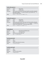
UVMapper 411
Table 13.21 Planar Mapping Options
Option Description
Alignment This allows you to specify the axis along which the model will be mapped.
Orientation This allows you to alter the layout of the texture map template. It only has an
effect when using the Split option (described later in this table). If you select Don't
Split, the Orientation option has no effect. When splitting the model into front and
back sections, you can have the two halves side by side (Horizontal) or above and
below each other (Vertical). Which you want to use really depends on the
geometry of the model. If you don't like the layout of the texture map after using
planar mapping, try changing this option.
Map Size This will specify the maximum dimension of the texture map template. Depending
on the model it may be vertical or horizontal, but the texture map is guaranteed
not to exceed this value in either width or height. One side will equal this value,
and the other will be scaled accordingly.
Split This option allows you to divide the texture map into front and back sections. (To
adjust the placement of these sections, see the Orientation option earlier in this
table.) You have three options. Don't Split will give you one map with the front
and back facets on top of each other. By Orientation will calculate the facet
normals, placing all facets that face toward the eye on one side, and placing all
facets that face away on the other. By Position with Offset of allows you to divide
the model based on geometry rather than facing. Using an offset of 0 will divide
the model in half. You can adjust this offset to change how many facets are on
each side.
Gaps in Map This allows you to separate the sides of the box on the texture map. If the sides
touch, sometimes you will see one pixel of the side on the front, for example.
Scale Result Use this option to specify how much larger or smaller the resulting texture map
should be.
Table 13.22 Box Mapping Options
Option Description
Map Size This will specify the maximum dimension of the texture map template. Depending
on the model it may be vertical or horizontal, but the texture map is guaranteed
not to exceed this value in either width or height. One side will equal this value,
and the other will be scaled accordingly.
Split front/back Setting this option will divide the model into six sections: front, back, top, bottom,
left side, and right side. Uncheck this option if you want to combine top and
bottom, left and right, front and back, giving you only three sections.
Gaps in Map This allows you to separate the sides of the box on the texture map. If the sides
touch, sometimes you will see one pixel of the side on the front, for example.
Scale Result Use this option to specify how much larger or smaller the resulting texture map
should be.
Team LRN
Please purchase PDF Split-Merge on www.verypdf.com to remove this watermark.