Tài liệu 3D Game Programming All in One- P19 pptx
Bạn đang xem bản rút gọn của tài liệu. Xem và tải ngay bản đầy đủ của tài liệu tại đây (1.33 MB, 30 trang )
5. Adjust the mesh rotations to match the pose in Figure 14.78. You want the charac-
ter slightly bent at the knees, with his left arm slightly bent beside him and the
right arm bent up at 90 degrees. Starting with the base node and moving on to the
pelvis, hips, and shoulders (in that order), adjust the joints of the skeleton.
Remember to rotate hip, knee, elbow, and shoulder joints to move the joints at the
extremities. Pay particular attention to the placement of the pelvis, lower spine,
and hip nodes. The pelvis should be well below the level of the hip nodes, and they
should be just a tad higher than the lower spine.
note
The node names and bones you see in Figure 14.77
are not in any way standard.They don't have to be.
However, there are standard skeletons for other
games that you can use. Torque also has a stan-
dard biped skeleton that is the same as the one
used for CounterStrike. But we can't really take
advantage of it, because it is only useful with
sequence files, which we do not yet have the abil-
ity to use given the current DTS Exporter that is
available. So we may as well use our own skeleton.
Rigging: Attaching the Skeleton
Now we have the skeleton built, the nodes have been named, and the bones are aligned
into a pose we like. Next we are going to attach our model to the skeleton. That way, when
the skeleton is manipulated, the mesh of the model will follow suit. It is during this step
that you might be inclined to thank me for insisting that you retain mesh groups for the
different model components like arms and feet and so on!
Rigging the Head
We'll begin with the head, just to get a feel for the rigging operation.
1. In the Joints tab in the toolbox, choose the joint (or node) named "head". Make
sure it appears highlighted in red in the wire-frame views.
2. Switch to the Groups tab and choose the head mesh. It should appear highlighted
in red, as you already know.
3. Switch back to the Joints tab and click Assign. Now the head mesh is assigned to
the head node. To double-check, just click anywhere in a blank space in a wire-
frame view to make sure that no objects are selected, choose the head joint to
ensure it is selected, and then click the SelAssigned (Select Assigned) button. The
head mesh should appear highlighted. If not, go back and repeat these three steps.
Character Animation 447
Figure 14.78 The pose-adjusted skeleton.
Team LRN
Please purchase PDF Split-Merge on www.verypdf.com to remove this watermark.
Aw shucks, there it is—the head is now rigged! Of course, that's not the end of the story.
There is still the rest of the model.
There's also the issue of what to do when a bone is rigged wrong. Sometimes it's a trivial
fix, and other times you might have to rerig the whole model. Or you might have to rig a
model by attaching a node to just a few vertices rather than a whole mesh or submesh.
That can get very, um, fiddly—I guess that would be a reasonable description.
Part of the simplicity in rigging this model comes from the technique we used; building
from primitives allows us to easily define meshes and submeshes. We'll use a "one node
per mesh" rule of thumb. It can get trickier using other techniques, but sometimes those
other techniques might be more appropriate for the model you want to build. It's a judg-
ment call, as everything important tends to be. There is one exception—as there always
is—to the "one node per mesh" rule that we'll get out of the way next.
Rigging the Torso
Okay, so the head was a cakewalk. It wasn't even necessary to show any pictures for you to
be able to follow along. How about the torso then—duck soup again, no?
Well, yes…I mean no, actually. No duck soup for this one!
The head mesh is attached to the head node, and that is fine. Tilting or rotating the head
node will indeed move the head in the manner we want. There really isn't a whole lot to
choose from. The neck is more a part of the spine than the head. The camera and mount1
nodes aren't even related to the skeleton. They are special nodes that will have a different
role to play in Torque, which we'll cover later. So that leaves the head node to control the
head mesh.
The torso, though, has at least five nodes that it might be attached to. But which should it
be? Let's eliminate the neck node for now. That leaves the spine nodes or the pelvis node.
Actually we can use more than one node for a mesh giving different parts of the mesh to
different nodes. When we built the torso mesh, we actually combined two primitives
together, remember that? One was the chest cylinder, and the other was the abdomen
cylinder. We could have left them as two separate submeshes, but I wanted to show you
how to join them together. We can still use them as if they were two separate meshes, by
assigning their respective vertices to different nodes.
If you look at the nodes, you'll see that the pelvis node is pretty well the obvious candi-
date to control the abdomen part of the mesh. The upper spine node, although probably
not as obvious, is likely the best candidate for the other node, because it exists in circum-
stances similar to the pelvis—there are limbs attached. So we'll go with these two and see
how that works out.
Chapter 14
■
Making a Character Model448
Team LRN
Please purchase PDF Split-Merge on www.verypdf.com to remove this watermark.
What this will mean in terms of animation is that we can have the vertices that are
attached to one node move in one way, while the vertices attached to the other node move
differently. Or not. It all depends on how you rig it.
None of this is strictly necessary. The animations we are going to create don't actually require
the torso mesh be given more than one node, but it's a good thing to learn, so we'll do it.
1. To get started with rigging the torso, let's tidy up the ol' drawing board a bit by
hiding all the meshes except the torso mesh. If you've forgotten how, just go to the
Groups tab of the toolbox, choose each mesh, and click Hide. Unfortunately, we
can't selectively hide parts of the skeleton. It's either all or nothing when it comes
to the bones.
2. Choose the pelvis node in the Joints tab.
3. Switch to the Model tab and set the Select tool to Vertex mode. Then select the ver-
tices that are the abdomen. You can use either the Front view or the Side view. Fig-
ure 14.79 shows the vertices to select.
4. Back in the Joints tab, click Assign. Now the vertices are attached to the pelvis
node.
5. Now choose the upper spine node, and then select the vertices for it, using Figure
14.80 as a guide.
6. Click Assign in the Joints tab, and that should do it.
7. Double-check to make sure you didn't overlook any of the vertices by choosing
each node in turn, clicking the SelAssigned button, and looking to see which
vertices for that node might
have been missed. If you did
miss any, you can simply select
the node, select the vertices, and
then click Assign to add them to
the nodes list.
There, that's the torso. It might not have
seemed so difficult a task to you, but to
me it was a nightmare! Well, maybe not
that bad, but it shows you the kinds of
decisions you will have to make when
rigging your models. What goes where
and how best will it work?
Now that we have a few nodes rigged,
let's take a look and see what they
actually do.
Character Animation 449
Figure 14.79 The abdomen vertices.
Figure 14.80 The chest vertices.
Team LRN
Please purchase PDF Split-Merge on www.verypdf.com to remove this watermark.
1. If you don't have a button at the lower right called "Anim," then choose Window,
Show Keyframer, and make sure there is a check mark there.
2. Click Anim to activate the Keyframer.
3. Using the Select tool in the Joint mode, select the pelvis joint (or you can use the
Joints tab to do the selection).
4. Use the Rotate tool in freeform mode in the Right Side view. You will recall that
freeform rotation is a simple matter of selecting the Rotate tool, then clicking in
the wire-frame view, and dragging the cursor left and right.
Now what you should be seeing is the entire torso, plus the head, rotate around the pelvis.
You should also see some strange things as well. The arm, leg, foot, and hand meshes don't
move. That's because they aren't rigged yet.
But notice that the leg bones are rotating when you rotate the pelvis. Aha! I don't know
about you, but when I bend over, my legs don't move back. Well, not unless I'm floating
in water, of course. So the pelvis node, while it seems to be an obvious candidate for bend-
ing your character at the waist, looks to not be the right one.
So go back, right now, and change it. It's simply the same procedure I showed you for the
pelvis, except you do it for the lower spine node. Make sure to click the Anim button to
take it out of the Keyframer first, or you won't be able to make the changes. I'll wait.
Musical Interlude.
There you are. Now that that's done, go back into the Keyframer as I showed you before,
and check the rotation of the lower spine node.
Another Musical Interlude.
Good! So everything should be working as expected now. The torso and the head meshes
bend over in unison, and all the bones attached above the lower spine bend in unison, as
shown in Figure 14.81. As you've probably
deduced, it is now a reasonably minor
matter to rig the rest of the nodes. Use
Table 14.2 to guide you in your rigging.
You just need to match a mesh to a node,
attach it, and move on. I'm enjoying the
music here, so you go ahead and do the
rest of the rigging, and I'll sit back and
relax.…
Yet Another Musical Interlude.
Great! With that done, let's move on.
Chapter 14
■
Making a Character Model450
Figure 14.81 Bending at the lower spine.
Team LRN
Please purchase PDF Split-Merge on www.verypdf.com to remove this watermark.
Idle Animation
The idle animation is the one used by Torque when the character is just standing there,
doing nothing in particular. In some games you will see some pretty complex idle anima-
tion where the character scratches himself in rather inconvenient locations, looks around,
scuffs his feet, and so on. We're just going to do a basic breathing sequence so that you'll
know that the character is alive. The name for the idle animation in Torque is root.
Even with a basic animation, the watchword is subtlety. Don't overdo it.
1. Make sure the Keyframer is enabled by clicking the Anim button in the lower-right
corner.
2. Set the number of frames in the Keyframer to 30. Do this in the right-hand edit
box in the lower-right corner of the Keyframer (see Figure 14.82).
3. Move the slider to the 1st frame.
Character Animation 451
Table 14.2 Hero Rigging
Node Mesh to Be Rigged
ZHead Head
UpperSpine Torso—chest-area vertices
LowerSpine Torso—abdomen-area vertices
LShoulder LArm
RShoulder RArm
LElbow LHand
RElbow RHand
LHip LThigh
RHip RThigh
LKnee LFoot
RKnee RFoot
Figure 14.82 The Keyframer control panel.
Team LRN
Please purchase PDF Split-Merge on www.verypdf.com to remove this watermark.
4. Choose Animate, Set Keyframe. This indicates that this particular frame is a keyframe.
5. Move the slider to the 15th frame.
6. Take note of the angle of the elbows and hands.
7. Select the midspine node and rotate it 5 degrees around the X-axis.
8. Rotate each of the elbows in the opposite direction by about 5 degrees to place
them back where they were before.
9. Choose Animate, Set Keyframe to set the keyframe attribute for this frame.
10. Move the slider back to the 2nd frame.
11. Choose Animate, Copy Keyframes.
12. Move the slider to the 30th frame.
13. Choose Animate, Paste Keyframes.
14. Save your work!
Figure 14.83 shows the subtle pose difference between the 1st and the 15th frames. Now
you can test your animation by clicking the Play button on the Keyframer controls. The
Play button is the one that looks like a single arrow pointing to the right.
As long as the Play button is down, the animation will loop. If you find it runs too fast,
you can change the FPS number in the Preferences dialog box to a lower value to slow the
animation.
Notice that when the animation is actually running, that subtle pose change becomes
quite noticeable.
tip
An excellent tool called characterFX is useful for creating animations, and it works well with Milk-
Shape. Unfortunately, for logistical reasons it could not be included with the tools on the compan-
ion CD. However, it does a great job of streamlining the process and is flexible, so a quick Google
search for it on the Internet might be worth your while!
Run Animation
The run animation is the staple of first-person
shooters. Run and shoot, run and shoot. Our
Hero character has a somewhat awkward lower
body, which will tend to make any animation
of him running look a bit goofy. Well, we'll
turn that into a feature and capitalize on that
goofiness.
Chapter 14
■
Making a Character Model452
Figure 14.83 The difference in poses.
Team LRN
Please purchase PDF Split-Merge on www.verypdf.com to remove this watermark.
1. Set the Keyframer to 120 frames. Additional frames will be added after the 30 you
started with for the idle animation.
2. Move the slider to frame 31.
3. Make sure that Operate on Selected Joints Only in the Animate menu is enabled.
4. Rotate the right hip joint slightly and then choose Animate, Set Keyframe. The
pose should be similar to the resting pose. The reason why we touched that hip
joint at all is to ensure that there is at least one joint in the frame that was affected
so that a keyframe will be made. You should have a pose much like that shown in
Figure 14.84.
5. Move the slider to frame 40.
6. In the Right Side view, select the Base joint, and
move it forward by one grid square and up
about three-quarters of a grid square, as shown
in Figure 14.85. This movement of the base
joint moves the entire model—it's a transfor-
mation across the ground. This transformation
is necessary in order to notify the Torque
Engine that the model is moving and how fast it
is moving. It doesn't need to be precise, but it
does need to be there.
7. Select the right hip, and then in the Side view
rotate it so that the leg moves forward.
8. Rotate the right knee forward as well, until the
leg matches the configuration in Figure 14.85.
9. Repeat the rotations for the left leg and move it
backward. In order to get things looking right,
you might have to adjust the joint positions
slightly by moving them, but not by much.
10. Rotate the left arm using the left shoulder node
and the left elbow node, swinging the hand for-
ward until it is approximately opposite the right
leg, as shown in Figure 14.85.
11. Set frame 40 to be a keyframe.
12. Move the slider to frame 50. Use Figure 14.86 as
the guide for this frame.
13. Move the base node one more grid square to the
right, but this time move it back down to the
ground level.
Character Animation 453
Figure 14.84 Frame 31.
Figure 14.85 Frame 40.
Figure 14.86 Frame 50.
Team LRN
Please purchase PDF Split-Merge on www.verypdf.com to remove this watermark.
14. Move all of your legs and joints back to approximately the same configuration as
in frame 31.
15. Swing the left arm down to the side of the model.
16. Set this frame (50) to be a keyframe.
17. Move to frame 60. Use Figure 14.87 as the guide for this frame.
18. Pose frame 60 the same as frame 40, except swing the legs in the opposite direc-
tions.
19. Swing the left arm back and rotate the elbow so that the left hand comes up paral-
lel to the ground.
20. Set this frame to be a keyframe.
21. Move to frame 70. Use Figure 14.88 as the guide for this frame.
22. Swing the arms and legs back to roughly the pose they had in frame 31.
23. Set this frame to be a keyframe. Use the Play Forward button to watch the anima-
tion. If the animation seems to be too fast or too slow, change the FPS setting in
the Preferences dialog box until it seems right, and take note of the value you use.
Now you have probably noticed that although we set the pose in only five frames, the pro-
gram automatically interpolated, or figured out, what the in-between frames should look
like. Torque does the same thing for us when we use
the model in-game. This is goodness. That's as much
of the run animation as we're going to do here, but you
should practice working with this for a while. The first
place you should start is to set the keyframe exactly in
the middle of the ones we've already set—at frames 35,
45, 55, and 65—and adjust the leg positions to get a
better animation from the legs.
Don't try too hard to make the animation look natural
though—he's a goofy character and should have that
sort of goofy, cartoonlike appearance when running.
Head Animation
This is the animation that Torque automatically
invokes when it needs to know how far your charac-
ter is looking up or down. So basically this anima-
tion's purpose is to define limits or a boundary and
not so much the movement. However, if your charac-
ter's facial or head shape would change when looking
up or down, then you would create a more complex
head animation.
Chapter 14
■
Making a Character Model454
Figure 14.88 Frame 70.
Figure 14.87 Frame 60.
Team LRN
Please purchase PDF Split-Merge on www.verypdf.com to remove this watermark.
That being said, it is really quite quickly dealt with.
1. Move to frame 71.
2. In the Right Side view, rotate the head joint until the head is looking up at the
maximum angle you want to allow. You may also need to move the head back a
bit.
3. Make this a keyframe.
4. Move to frame 72.
5. Rotate the head joint until the head is pointed down at the maximum angle you
want to allow. You may also need to move the head forward a bit.
6. Make this a keyframe also.
7. Save your work! There, you are done. That's the entire animation sequence! Check
your frames against Figure 14.89 to make sure you got it all right.
Headside Animation
In the same way that the head animation defines the limits for the up and down motion
performed by Torque, the headside animation provides the limits for the left and right
motion. This is most visible from the third-person perspective when in the game.
Do the same thing you did for the head animation, but use frame 73 for the left turn and
frame 74 for the right turn. Make each of these frames a keyframe, and save your work
when you finish.
Look Animation
The look animation is basically another movement-limiting animation that defines how
the character's arms will be posed when he is looking up or down. Again, it is a simple
two-frame animation that doesn't require us to go into in detail now. Use frame 75 for the
down "look," or aim. Make sure you have both arms positioned sensibly. Use frame 76 for
the up aim. Set both as keyframes and save your work again.
Death Animation
As you saw earlier, there are many possible ways to die. Torque supports 11 "standard"
death animations, but you can easily
add more by writing a minor code
change into the scripts.
We'll cover only one death animation
here. We'll have the character collapse
backward and fall to the ground on his
back with his feet tossing into the air
and back down again.
Character Animation 455
Figure 14.89 Head sequence frames.
Team LRN
Please purchase PDF Split-Merge on www.verypdf.com to remove this watermark.
1. Move to frame 81 and set the pose back to resemble the resting pose as closely as
you can, without spending too much time on it.
2. Set this frame to be a keyframe.
3. Move to frame 90 and rotate the arms and hands to match. You can have the char-
acter's head pop off temporarily, like I do, or leave it on but thrown back. It's your
model! Let Figure 14.90 guide you.
4. Set frame 90 to be a keyframe.
5. Move to frame 100.
6. In the Side view, drag the base node backward several grid squares.
7. Continue to rotate and move the arms and legs, and rotate the body around the
pelvis node to make the body tipped past the horizontal with the bottom of the
torso higher than the top, as shown in Figure 14.91.
8. If you haven't guessed it by now, make this frame a keyframe!
9. Move to frame 110.
10. The body is hitting the ground, with
some momentum still in the legs.
Align the bottom of the torso (which
is actually the character's back) even
with the ground. Rotate the legs and
knees to fling the feet up over the
body, and rotate the arms to fling
them away from the body, as shown
in Figure 14.92. By now the base
node should be eight or nine grid
squares behind the origin along the
Z-axis, as seen in the Side view.
11. Yup, this is another keyframe. Go
ahead, make its day.
12. Now for the final resting position.
Move to frame 120.
13. Lay the body out, flat against the
ground. Also, move the base node
one or two more grid squares farther
back, to cause the body to slide along
the ground. Lay the arms flat to the
sides, the feet and legs down on the
ground and spread somewhat. Tilt
the head back. As you can see in Fig-
ure 14.93, he's dead, Jim.
Chapter 14
■
Making a Character Model456
Figure 14.90 Frame 90.
Figure 14.91 Frame 100.
Team LRN
Please purchase PDF Split-Merge on www.verypdf.com to remove this watermark.
14. Keyframe him, Dano! (Okay, that's
an obscure reference, I'll admit.
Indulge me!)
15. Save your work!
Well, that's the lot of them. Enough ani-
mations to give you what you really need
to know to get moving on animating for
Torque in MilkShape. There's still more
to cover—we're not quite out of the
woods yet. Now we have to tell Torque
how to find the animations.
The Animation Sequence Materials
The Torque Engine needs to know where
the various animations can be found, how
long they run, what type they are, and
how fast they should be run. We do this
using a technique called the Animation
Sequence Materials.
The general approach is that we create a
special material, and embedded in the
name of that material are the Torque
name for the animation sequence, its
desired playback frame rate, which frames
belong to which sequences (inclusive from start to end), and whether the sequence cycles
(loops) or plays once per invocation.
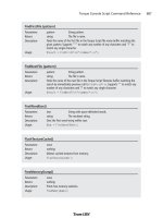
You need to go to the Materials tab of the toolbox and create six new materials—one for
each animation sequence. Table 14.3 lists the material names you need to use. The text in
the "Sequence Material Name" column must all be included in the name, exactly as
shown. These special materials tell the Torque DTS Exporter program what special oper-
ation to perform on the model as it creates the DTS formatted file for use in Torque.
Note that some of the Sequence Material Names don't include some of the option set-
tings. If you leave them out, the defaults are used. A little later in this chapter you'll find
more detail about the exporter.
Finally, there is one more special material we need to make, in order to set the global scale.
We built this model on a large scale so we could use the Snap To Grid function without
seeing our vertices snapped way out of line. Now, when we export the model, we will need
to have it scaled down. Add a material and name it "opt:scale=0.02". This will shrink the
model to one-twentieth its created size, which is about right for our needs.
Character Animation 457
Figure 14.92 Frame 110.
Figure 14.93 Frame 120.
Team LRN
Please purchase PDF Split-Merge on www.verypdf.com to remove this watermark.
Exporting the Model for Torque
In the next section of this chapter, we will look at the Torque DTS Exporter for MilkShape,
but for now we'll just use it in a fundamental way to get our model to work in Torque.
1. After saving your work, choose File, Export, Torque Game Engine DTS. You will
see the Torque Game Engine (DTS) Exporter dialog box appear.
2. We're going to take the defaults, but we should make sure they are correct. You
want to have Export animation and Export material information selected, and
Collision Mesh should be set to None (Torque handles player collision internally).
Click OK when ready.
3. Save your DTS file as C:\3DGPAi1\resources\ch14\myhero.dts.
That was pretty painless. Now let's make sure the model works! We'll dust off the old
Torque Show Tool we used in Chapter 9 and check out the model.
1. In Windows Explorer browse your way to C:\3DGPAi1 and launch the Show Book
Models shortcut.
2. Click Load Shape.
3. Find RESOURCES/CH14/myhero.dts, choose it, and click Load.
4. The model should appear in the center of the screen, facing away from you.
5. Use the navigation keys (described in Chapter 9 in Table 9.1) to rotate the model
and bring it closer to you. You should notice that it is already performing the idle
animation (root).
6. Click Thread Control. A window will appear on your screen, probably at the lower
right. Drag it to the upper-left corner, or wherever is most convenient.
7. Click Run in the Sequences list. The character should start the run sequence.
8. Check out the other sequences, but remember, the ones that don't cycle are going
to run just once and will stay at the last frame. You can use the Transitions button
to adjust the transition speeds so that you can check to see if you are getting your
desired results.
Chapter 14
■
Making a Character Model458
Table 14.3 Animation Sequence Material Names
Torque Sequence Name Sequence Material Name
root seq:root=1-30,fps=10,cyclic
run seq:run=31-70,fps=15,cyclic
head seq:head=71-72
headside seq:headside=73-74
look seq:look=75-76,fps=15
die1 seq:die1=80-120
Team LRN
Please purchase PDF Split-Merge on www.verypdf.com to remove this watermark.
9. If necessary, go back to your model in MilkShape and make adjustments to your
animations, and then come back here to check them out.
Good job! The rule of thumb is, if it works in the Show Tool, it will work in the game,
because the Torque Engine is behind both.
You now have an animated Hero character to use in your game! And it really isn't that dif-
ficult. If you are even a halfway decent artist and have a good eye, I'm sure your model and
animations are much better than mine.
The next section provides some detail into the workings of the DTS Exporter for the
Torque Engine. With its help, you should take some time to fiddle with settings and dif-
ferent animations and add your own animation sequences.
The Torque DTS Exporter for MilkShape
The Torque DTS Exporter is included in your C:\3DGPAi1\resources\tools directory and
is called ms2dtsexporter.dll. Copy this file into your MilkShape directory, C:\Program
Files\MilkShape 3D 1.6.6, and then restart MilkShape. The name of the MilkShape folder
changes from version to version, so watch out for that. The exporter shows up under the
File, Export menu.
The Torque Game Engine (DTS) Exporter Dialog Box
The Torque Game Engine (DTS) Exporter dialog box (see Figure 14.94) has three groups
of options, none of which normally need to be set. Option settings are not saved, so you
rarely use this dialog box for more than just a means to double-check your option values.
The recommended approach is to set options using special materials.
Collision Mesh
The exporter allows you to
create as many collision
meshes as you want. Each
collision mesh must be
named "Collision"; if you
have three collision meshes,
they will all be named
"Collision". If you do not
have a collision mesh
defined, you may have the
exporter create one for you
as either a box or a cylinder.
The Torque DTS Exporter for MilkShape 459
Figure 14.94 Torque Game Engine (DTS) Exporter dialog box.
Team LRN
Please purchase PDF Split-Merge on www.verypdf.com to remove this watermark.
You can also manually select an existing mesh. Player-characters don't need a collision
mesh at all.
Select the Create a visible copy of the collision mesh check box to make the mesh visible
as well as collidable.
Animation Settings
The Animation Settings group displays the global values for the Animations.
■
Frames per second. This field indicates at what speed the Torque Engine should
play at the animations. This field can be set using an Export Options material and
applies globally to all animation sequences. This does not affect the number of
keyframes; it simply sets the rate at which they will be played.
■
Export animation. If the shape is animated, but no animation sequence has been
defined for it, then this field contains the name that will be assigned to it. The
sequence will cover the full timeline. This feature is useful for simple models with
a single animation sequence.
Other Settings
The Other Settings group contains miscellaneous settings values.
■
Global scale factor. The global scale factor is the amount by which the shape is
scaled when it is exported. The default scale factor is 0.1, but this field can be
changed to any value set using an Export Options material.
■
Minimum visible size (pixels). If the projected screen size of the bounding radius
of the shape drops to the minimum visible size, the shape will no longer render.
This is normally used to switch between different detail levels, and it's recom-
mended that you leave this at the default value: 0.
■
Export material information. You may disable the exporting of material informa-
tion (not recommended) by clearing the Export material information check box.
Special Materials
MilkShape does not directly support a number of Torque Engine features, so the tool has
been extended through the use of several clever uses of existing MilkShape features, based
on material and mesh names. These are described more fully in the following sections, but
they basically fall into two categories: mesh flags embedded in the mesh's name and spe-
cially named materials that are used to declare animation sequences and exporter options.
Special materials are materials that are not exported as real materials but are instead used
only to store information in the MilkShape file. These materials are processed by the
exporter but are not written into the DTS file.
Chapter 14
■
Making a Character Model460
Team LRN
Please purchase PDF Split-Merge on www.verypdf.com to remove this watermark.
Export Options
Materials with special names can be used to set several export options. These materials are
ignored during export and are solely used to set options.
Option materials are named as follows:
opt: option, option,
All other properties of the material are ignored. Table 14.4 lists the available options.
There may be more than one option material. If the same options are set on multiple
materials, then the last one in the material list is the value used. Here are a couple exam-
ples of valid material names:
opt: fps=10, cyclic
opt: scale=0.1
Material Option Flags
Material attributes can be set using the MilkShape Shininess and Translucency sliders as
well as by embedding additional flags in the material name.
Environment mapping can be controlled for the model by use of the Shininess slider—it's
the one on the left-hand side. Setting the slider to any value but 0 will enable environment
mapping for the texture. Note that the texture you are using must have an alpha channel,
which will be used to control the per-pixel shininess of the texture. Any value of the slid-
er other than 1.0 or 0.0 will be ignored.
You can enable translucency by setting the MilkShape Translucency slider—this is the
slider on the right-hand side. Setting the slider to any value other than 1.0, which is to the
far right, will enable translucency for the texture. The texture you are using must have an
The Torque DTS Exporter for MilkShape 461
Table 14.4 Export Options
Option Description
scale=n The global shape scale factor, where n is a floating point value. The default scale
value is 0.1.
size=n The global minimum visible pixel size. The default is 0.
fps=n The global default frames per second value for animations. Each animation
sequence may set this value, but if it's not defined by the sequence, this default
value is used.
cyclic The global default animation looping flag. Each animation sequence may set this
value, but if it's not defined by the sequence, this default value is used.
Team LRN
Please purchase PDF Split-Merge on www.verypdf.com to remove this watermark.
alpha channel, which will be used by the Torque Engine to control the per-pixel translu-
cency of the texture. Any value of the slider other than 1.0 or 0.0 will be ignored.
Options that are embedded in the material name follow this format:
name: flag, flag,
where the
:
and
flags
are optional. Table 14.5 shows which flags are available.
A self-illuminating additive material could be called as follows:
Flare: Add, Illum
Mesh Option Flags
Meshes can have additional flags embedded in the mesh (or group) name. The mesh
name follows this format:
name: flag, flag,
where the
:
and
flags
are optional. Table 14.6 shows which flags are available.
Chapter 14
■
Making a Character Model462
Table 14.5 Material Option Flags
Flag Description
Add Enables additive transparency.
Sub Enables subtractive transparency.
Illum Enables self-illumination (lighting doesn't affect it).
NoMip Disables mipmapping.
MipZero Sets the "MipMapZeroBorder" flag.
Table 14.6 Mesh Option Flags
Flag Description
Billboard The mesh always faces the viewer.
BillboardZ The mesh faces the viewer but is only rotated around the mesh's Z-axis.
ENormals This flag encodes vertex normals. It is deprecated and should not be used unless
you know what you're doing.
Team LRN
Please purchase PDF Split-Merge on www.verypdf.com to remove this watermark.
Here are some legal mesh or group names:
■
leaf
■
leaf: Billboard
■
leaf: BillboardZ
By default, meshes do not have any flags set.
Animation Sequences
MilkShape only provides a single animation timeline, but the Torque Engine supports
multiple animation sequences, each of which can be named and have different properties.
Multiple sequences in MilkShape are animated on the main timeline and are split into
separate sequences by the exporter. For this to happen animation sequences must be
declared, indicating where each sequence starts and ends on the master timeline. This is
done through materials with special names. These materials are ignored during export
and are solely used to declare animation sequences. The section on Special Materials
above provides more details.
Sequence materials are named as follows:
"seq: option, option, …"
All other properties of the material are ignored. Table 14.7 describes the Sequence
Material Options.
Here are some valid sequence declarations:
seq: fire=1-4
seq: rotate=5-8, cyclic, fps=2
seq: reload=9-12, fps=5
The Torque DTS Exporter for MilkShape 463
Table 14.7 Sequence Material Options
Option Description
name=start-end This declares the name of the sequence followed by the starting and ending
keyframes. This option must exist for the sequence declaration to be valid.
fps=n This is the number of frames per second. This value affects the duration and
playback speed of the sequence.
cyclic Sequences are noncyclic by default. Cyclic animations automatically loop back to
the start and never end.
Team LRN
Please purchase PDF Split-Merge on www.verypdf.com to remove this watermark.
Moving Right Along
That was a pretty busy chapter, huh? We created a character model and a texture skin for
it, created a skeleton and rigged the model's meshes to the skeleton, and then proceeded
to animate the skeleton. It's a lot of work, and that's why even the smallest game develop-
ment team usually has at least one modeler on board to handle that workload.
So now that you can create your own player-character, it's time to create some sort of
transportation so he can get around in the game world. That's the subject of the next
chapter, "Making a Vehicle Model."
Chapter 14
■
Making a Character Model464
Team LRN
Please purchase PDF Split-Merge on www.verypdf.com to remove this watermark.
465
Making a
Vehicle Model
chapter 15
I
n Chapter 9 we looked at creating skins, and during that process we created a skin for
a cool runabout-type vehicle. In this chapter we'll create the model itself.
Of course, there is a whole host of different vehicle types, such as those for the open road
or off road, aircraft, hovercraft, ships, and so on. In most cases the methods used to cre-
ate the vehicles can be used with any type of object. But different vehicle types have dif-
ferent capabilities and therefore may require some specialized accommodation for those
capabilities in the models.
For example, if you want your vehicles to be drivable by a player-avatar that gets into the
vehicle when you want to drive, then your vehicle will need mount points, which are spe-
cial nodes or subobjects within the model that indicate where your player-avatar gets
attached to the vehicle. Different vehicle types, makes, and models will have different
needs in this area.
Then there are those special nodes that indicate where other game functions will happen:
Wheeled vehicles need to know where the wheels are located, as well as information about
how the springs and steering mechanisms are oriented.
Some vehicles might need nodes in their models to indicate to the engine where to gen-
erate engine exhaust smoke using particles. Flying vehicles may require nodes to help the
engine generate contrails (condensation trails). The list goes on.
Team LRN
Please purchase PDF Split-Merge on www.verypdf.com to remove this watermark.
The Vehicle Model
In this chapter we are going to build a complete wheeled vehicle—the runabout, which
will wear the skin you created in Chapter 9. Then we will insert it into a little test game so
that we can carom about and drive our insurance rates through the roof!
The Sketch
I find the best way to start a new model is with a sketch. Doodle out some ideas, and keep
working them up on paper until you get something that suits your needs. Then choose a
view (Left or Right, Top or Bottom, Front or Back) that presents you with the most num-
ber of intersections of lines to use as points.
Figure 15.1 shows a sketch of the runabout from the right-hand side. Notice that it is really a
sketch and not a drawing. As long as the general proportions and coarse features are present,
it's satisfactory. Now if you were going to model a real car, you might need to use a more
detailed sketch or perhaps something that would qualify more as a drawing than a sketch.
Then again you may not—it all depends on how much detail is necessary to suit your needs.
The Side view is the main sketch
we will use to make our model.
When modeling most vehicles,
you will usually use a Side view
as your primary source for
extrusion modeling. The reason
for this is pretty obvious: Most
vehicles are longer than they are
tall or wide. The symmetries of
vehicles (how one side mirrors the other) tend to reflect
around the longitudinal axis, the one that runs from the rear
to the front of the vehicle up the middle.
The Top view of the runabout is shown in Figure 15.2. The
purpose for sketching this view is to provide a guide for your
modeling efforts as they proceed. You will find yourself
checking back against this drawing quite often.
One more useful thing is to make a copy of the Side view and,
using Paint Shop Pro, adjust the brightness of the image. This
is because when we import the sketch into MilkShape, we
don't want the image to overpower any of the on-screen mod-
eling marks we make. I find the best approach is to darken the
whole image by around 40 to 50 percent and reduce the con-
trast by about 50 to 60 percent or so. Figure 15.3 shows the
Chapter 15
■
Making a Vehicle Model466
Figure 15.1 Side view sketch of the runabout.
Figure 15.2 Top view
sketch of the runabout.
Team LRN
Please purchase PDF Split-Merge on www.verypdf.com to remove this watermark.
adjusted Side view. I keep the original
sketches as they were so that I can print
them out for reference purposes (and also
just to pin up on the wall because it's a cool
artsy thing to do).
The Model
So pour some gasoline in the ol' comput-
er, grab the pull-start, and fire up
MilkShape again if it isn't already running. If you need a quick refresher, you can jump
back to Chapter 14. Set your MilkShape GUI display to the four-view mode by choosing
Window, Viewports, 4 Window.
Create a fresh new MilkShape document. It's a good idea to save the empty file right now,
just to get the path set up and establish the file name.
Then you want to import the side sketch as the background in the Side view (Top Right view).
Right-click in the Side view and choose Choose Background Image from the pop-up menu.
Select your sketch and click OK. You can use my sketch if you want—it's located at
C:\3DGPAi1\RESOURCES\CH15\ref_sketch.bmp.
You should end up with something like Figure 15.4.
So now we start.
Building the Body
First, we'll build the body:
1. Select the Vertex tool, making sure that the
Auto Tool check box is cleared.
2. In the Side view, start placing vertices at all
the major corners and points around the
edge of the car's body—don't do the fenders
yet. See Figure 15.5 for reference.
note
There is also a string of vertices across the "waist" of
the body—in Figure 15.5 they are highlighted as black
squares (they show red in MilkShape).These extra ver-
tices are added for two reasons: First, they act as use-
ful anchors for creating the faces that we'll make later.
And second, they help add more malleability to the
model for shaping the sides of the car.
The Vehicle Model 467
Figure 15.3 Side view sketch adjusted for use in
MilkShape.
Figure 15.4 MilkShape windows with
reference sketch.
Figure 15.5 Placing vertices over the
reference sketch.
Team LRN
Please purchase PDF Split-Merge on www.verypdf.com to remove this watermark.
After we have the vertices placed, we move on to creating the faces joined by the
vertices.
tip
It's important to remember that when we create faces using the Face tool, we click on three vertices
in sequence to create one face.The order we click on the vertices is important.To create a face or poly-
gon that is facing toward us, we need to select the vertices in a counterclockwise order, as shown in
Figure 15.6. For most cases this is not hard to do, but it's possible to get confused and lose track of
the sequence. In this case you can use the Edit,Undo menu item to back up until the sequence is clear.
You can also abort any three-vertex sequence by just clicking on the Selection tool (or any other tool)
and then clicking back on the Face tool again. Then you can start with a fresh trio of vertices.
3. Starting at the right side (the front of the car), begin creating faces, moving to the left
along the top as you proceed, including the window area, as shown in Figure 15.7.
When you reach the left side, you should have something resembling Figure 15.8.
4. After completing the top row of faces, start making faces along the bottom, from
the left back over to the right (see Figure 15.9).
5. Finish up the faces for the side of the body. You should end up with something like
Figure 15.10.
Okay, so now we have a plane
of body faces. We want to make
sure they are all oriented cor-
rectly. The quickest way to do
this is to look at the output in
the 3D Perspective view. Make
sure the view (it should be the
Bottom Right view) is set to
Chapter 15
■
Making a Vehicle Model468
Figure 15.6 Vertex order for creating faces.
Figure 15.7 Creating faces starting from the
right.
Figure 15.8 Finishing the top row of faces.
Team LRN
Please purchase PDF Split-Merge on www.verypdf.com to remove this watermark.
either Flat Shaded or Smooth Shaded by
right-clicking on the view and then choos-
ing either Flat Shaded or Smooth Shaded in
the pop-up menu.
What you should see is the outline of the
body rendered in white or light gray, just as
in Figure 15.11.
tip
This is a long one, so make sure you've got some pop-
corn handy!
Sometimes you end up with two overlapping faces: one oriented correctly, and the other reversed.
These are hard to catch until they start showing strange results when rendering, as the model grows
more complex. There is another way to check for misoriented faces that is a little more involved:
1. Pick the Selection tool and set it to Face mode. Make sure that the Ignore Backfaces check
box is
selected
.
2. Now use the Selection tool to select all the faces by dragging the selection rectangle
around all of them. This will highlight all the faces.
3. Now choose Edit, Hide Selection. All of the correctly oriented faces will vanish, leaving
behind only the ones facing the wrong way.
4. To fix the problem, unhide all the hidden faces,
clear
the Ignore Backfaces check box, and
select all the faces again. This will select all correct and incorrect faces.
5. Then choose Face, Reverse Vertex Order. This will make the good ones bad, and the bad
ones good. Still with me?
6. Okay, now deselect everything by clicking the Select tool in an open area, and
select
the
Ignore Backfaces check box again.
The Vehicle Model 469
Figure 15.9 Working the bottom row of faces. Figure 15.10 Completed plane of body faces.
Figure 15.11 The 3D view of the initial
body faces.
Team LRN
Please purchase PDF Split-Merge on www.verypdf.com to remove this watermark.
7. Drag select over all the faces one more time. Now only the faces that were originally incor-
rect will be selected.
8. Choose Face, Reverse Vertex Order with those faces selected.
9. Then for one final time
clear
the Ignore Backfaces check box, select all the faces, and
choose Reverse Vertex Order. This should flip all faces back to the correct orientation. If
this reminds you of manipulating a Rubik's Cube, then you think a lot like I do!
So now we'll move on to adding some width to the body.
6. Choose the Selection tool and set it to Face mode.
7. Select all the faces.
8. Click the Extrude tool and fill in the X entry of the XYZ boxes with the value
Ϫ10.0 (that's minus ten point zero). Leave Y and Z at 0.0.
9. Click on the Extrude button to the
right of the XYZ boxes. You should
get a new set of polygons negatively
offset in the X-axis by 10 units, as
shown in Figure 15.12.
Notice the way that the image in the
3D view looks—now the body has
some depth to it. It's not just a plane
of faces anymore.
10. Repeat step 9 four more times, until
you get five segments as shown in
Figure 15.13. Warning: Do not click
on any other tool or in the edit win-
dows. After the fifth extrusion you
want to end up with the body faces
still selected.
11. The body faces should still be
selected if you got my warning in
time. Choose Edit, Duplicate
Selection.
12. Click the Move tool, then go to the
Top view at the lower left, and drag
the highlighted faces (these will now
be the copies, not the originals) to
the right, clear of the extrusion seg-
ments, so that you get something
like that shown in Figure 15.14.
Chapter 15
■
Making a Vehicle Model470
Figure 15.12 First extrusion.
Figure 15.13 After extruding the body faces five
times.
Team LRN
Please purchase PDF Split-Merge on www.verypdf.com to remove this watermark.
13. Choose Face, Reverse Vertex Order.
14. Using the Side views and Top views, align the vertices of the copy of the body faces
with their counterparts in the main body.
15. In the Top view drag the body face copy over to the right edge of the rest of the
body polygons. Align the vertices as best you can by eye.
tip
We want to make sure that the vertices in Step 15 are perfectly aligned. To do this, we'll scale our
entire model up. Making our model larger in relation to the grid allows us more precision with the
grid. This will help ensure good results when we snap our vertices to the grid, which is going to
happen shortly.
16. Select the entire set of polygons in all the faces, and then use the Scale tool to make
the entire model four times larger.
17. Select the entire model in vertex
selection mode, and choose Vertex,
Snap To Grid.
18. Choose Vertex, Weld Vertices.
19. Scale the model by 0.25. This will
restore the model back to its origi-
nal size.
20. In the Top view make sure the
entire model is selected, and then
use the Move tool to drag the
model over the sketch so that it is
aligned around the longitudinal
center of the car in the sketch.
You should now have a model that
looks like that shown in Figure
15.15.
21. In the Top view select the bottom
nine rows (or forwardmost nine
rows) of vertices.
22. Use the Scale tool to scale the selec-
tion to 0.9 in the X-axis only; leave
the other values at 0.0. Figure 15.16
shows the result of this operation.
23. Change your selection to be the
bottom eight rows and scale to 0.9.
The Vehicle Model 471
Figure 15.14 After duplicating and moving the
copies.
Figure 15.15 Scaling the nose of the runabout.
Team LRN
Please purchase PDF Split-Merge on www.verypdf.com to remove this watermark.