Tài liệu 3D Game Programming All in One- P21 doc
Bạn đang xem bản rút gọn của tài liệu. Xem và tải ngay bản đầy đủ của tài liệu tại đây (997.42 KB, 30 trang )
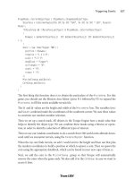
You will end up with a textured
bridge (see Figure 17.17) in your
3D view at the upper left.
11. For safety's sake, save your work,
by Choosing File, Save As File.
In the Save As Type combo box,
select Quake map file (*.map).
12. Choose Torque,
Export220map/Build High
Detail DIF.
This will export the map again,
overwriting what you just
saved (so you can see that you
could have gotten away with not doing the initial Save
As operation), and then compile the map to DIF format
and gather all of the used textures into the used textures
directory. Contrast this all-in-one operation with the
discrete steps we executed earlier when we did the
quick start with the default room. This is certainly more
convenient!
13. Copy the textures and the bridge.map file to C:\aEma-
gaCh6\control\data\structures.
There is already a bridge with that name in that directory
that is being used in the mission file. Go ahead and replace
that file, as well as the textures, if necessary.
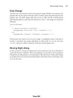
14. Launch Emaga6 and when you spawn in, turn to your
right and run to the edge of the wadi. You should see your
bridge spanning the wadi ahead of you, as depicted in Fig-
ure 17.18.
Building Bridges 507
Figure 17.14 A new cube.
Figure 17.15 The
Texture item in the
Object pop-up menu.
Team LRN
Please purchase PDF Split-Merge on www.verypdf.com to remove this watermark.
Building a House
The bridge was nice and certainly useful. But one must admit that it's fairly simple. Of
course, if you need a bridge you will probably make something more ornate.
In this section we will go a little bit farther and make something more complex: a house
with a door opening and a window and internal lighting.
1. Launch QuArK and open the Torque Map Editor. Delete the default room and save
the empty file as C:\QuArK 6.3\torque\tmpquark\maps\house.map.
2. Select the Cube brush and create a cube that measures 260 units in width by 360
units in length by 256 units in height. You can see the dimensions by hovering the
cursor over the cube and looking in the lower-left corner of the Map Editor window.
3. Create a smaller brush in front
of the first cube, as shown in
Figure 17.19. This will be used
to create the front stairs.
4. Select the new brush in the lower-
left window, and then right-click
to get the pop-up menu and
choose Stair. You will see your
brush change into a staircase, as
shown in Figure 17.20.
5. Select the large brush, right-click
to get the pop-up menu, and
choose Make Hollow. Your large
Chapter 17
■
Making Structures508
Figure 17.16 The Texture Browser.
Figure 17.17 The finished bridge.
Figure 17.18 The bridge in Emaga6.
Team LRN
Please purchase PDF Split-Merge on www.verypdf.com to remove this watermark.
brush will now be a hollowed
room and will look like the one
in Figure 17.21.
6. Create another brush and place
it in the wall above the stairs, as
shown in Figure 17.22. This
brush will be used for an opera-
tion called a subtraction.
7. Ensure that the new brush is
selected, right-click it, and
choose Brush Subtraction. You
will see a bunch of new lines
appear in the wall in which the
brush is embedded.
8. Select the Subtraction brush and
press the Delete key to make it
go away. You will see a hole in
the wall now, as depicted in Fig-
ure 17.23. This is the doorway.
9. Using the texture assignment
technique you learned in the
earlier sections of this chapter,
set the house's texture to con-
crete and the stairs' texture to
256_BrickA.
Now you have to add a special
brush of a type known as an
entity. Entities are constructs
used when making maps that
give special instructions to the
map compiler about things it
needs to do or understand when
it goes about building the DIF
version of the map for use in
Torque.
You are going to create an entity
called a portal. Portals tell
Torque how to go about lighting
the interior of the object when
Building a House 509
Figure 17.19 The Stair brush.
Figure 17.20 The stairs.
Figure 17.21 The hollowed room.
Team LRN
Please purchase PDF Split-Merge on www.verypdf.com to remove this watermark.
there is an opening. By placing
the portal in the doorway, you
can tell Torque that it should not
try to do its special interior
lighting outside the door. You
can also indicate whether or not
Torque will allow external light
to pass through the portal to the
interior.
10. Locate the Entities panel in the
upper-left portion of the Map
Editor, and in it find the Torque
Entities button. Click it.
11. Choose Brush-based entities,
portal, as shown in Figure 17.24.
12. An entry for the entity will
appear in the Tree view in the
lower-left portion of the Map
Editor, as shown in Figure
17.25.
13. Select the portal entity and then
click the Cube button to create a
Portal brush, as shown in Figure
17.26. A new brush will appear in
the model—this is the Portal
brush.
14. Reshape the Portal brush to be just a little larger than the doorway in width and
height, and a little narrower than the doorway in thickness, as you can see in Fig-
ure 17.27.
15. In the Tree view, double-click the portal icon (not the poly icon that it contains). A
small dialog box will appear; the bottom field is the parameter
ambient_light
set-
ting for the portal. Choose passes through from the combo box.
16. Using the texture assignment technique you learned in the earlier sections of this
chapter, set the portal's texture to
NULL
.
Next we are going to create another entity—a light entity. The process is similar to
the portal entity at first, but a light entity is a point entity, not a brush entity, so
things will be just a little different.
Chapter 17
■
Making Structures510
Figure 17.22 The Subtraction brush.
Figure 17.23 The doorway.
Team LRN
Please purchase PDF Split-Merge on www.verypdf.com to remove this watermark.
17. As before, go to the Entities
panel and find the Torque Enti-
ties button. Click it and choose
light_*entities, light_omni, as
shown in Figure 17.28.
18. A new light entity will be cre-
ated in the Tree view, and a
small rendition of a light bulb
will appear in your map. Move it
up closer to the ceiling, as you
can see in Figure 17.29.
19. Double-click the light_omni
entity in the Tree view to get to
its settings. Ensure that alarm_type is set to nor-
mal only.
20. Save your work and export it using the methods
you learned earlier in the Quick Start section.
21. Use UltraEdit to open the mission file for
Emaga6, C:\aEmagaCh6\control\data\maps\
book_ch6.mis.
22. Locate this line:
interiorFile = "~/data/structures/newmap.dif";
If the line doesn't exist in the file, then locate
this one:
interiorFile = "~/data/structures/hovelb.dif";
Change whichever line you find to reflect your new structure as follows:
interiorFile = "~/data/structures/house.dif";
23. Run Emaga6 and check out your new house, which should be in front of you. Go
on inside and see the effect the lighting has.
Building a House 511
Figure 17.27 The portal in place.
Figure 17.28 The light entity.
Figure 17.25 The portal
entity in the Tree view.
Figure 17.26 The portal
entity's brush in the Tree view.
Figure 17.24 The portal entity.
Team LRN
Please purchase PDF Split-Merge on www.verypdf.com to remove this watermark.
Moving Right Along
So, in this chapter you've learned yet
another tool. QuArK is an extremely
feature-complete tool for creating
structures for Torque. You've built the
two most common sorts of structures,
an outdoor structure (the bridge) and
a building with a lighted interior.
Your imagination is the only real limit
here—castles, complex underground
tunnel systems, factories, playgrounds,
and just about anything else can be
created with QuArK.
Normally, I would include a reference section for QuArK in this chapter. However, the
program has so many features and options that the material is just too hefty to present in
the chapter. Instead, I've included the QuArK reference in Appendix D.
In the next chapter, we'll take a look at how to make things for the game world environment.
Chapter 17
■
Making Structures512
Figure 17.29 The repositioned light entity.
Team LRN
Please purchase PDF Split-Merge on www.verypdf.com to remove this watermark.
513
Making the Game
World Environment
chapter 18
I
n many games, having a full suite of character models, buildings, trees, and other
visual clutter is still not enough to accomplish the needed sense of immersion. There
are a number of other aspects to the game world that come from the world around
us that we often take for granted: the background sky, the appearance of water, the appear-
ance of clouds in motion, and the terrain. Figure 18.1 is a nice serene picture of ocean-
side forested hills just after sunset. No, it's not a photograph—it's a screen shot from the
game Tubettiworld being developed using the Torque Game Engine.
Now way back in Chapter 12 we covered terrains to a certain extent, so you probably have
a reasonable sense of what is involved with creating terrains using a height map. In this
chapter we will revisit terrains using the more labor-intensive method of manually build-
ing up a terrain with the in-game editor. We'll get into that at the end of this chapter.
First, however, we will visit sky, clouds,
and water—the environmental triad
of computer game ambience.
Skyboxes
When you are tasked to create a 3D
game that offers unrestricted player
movement in unlimited vistas, you will
need to come up with ways to provide
that open, outdoors perception.
A technique that works well is to pro-
vide a static background sky that con-
tains elements of the sky that we often
Figure 18.1 A serene scene.
Team LRN
Please purchase PDF Split-Merge on www.verypdf.com to remove this watermark.
take for granted, like clouds, and a color gradient that changes as you move farther away from
the horizon. We do this using a construct known as a skybox.
A skybox is a cube that surrounds the game player. The player stands inside the box, and
no matter which way he turns, he will see some part of the box as long as it isn't obscured
by other in-game objects. The box never rotates, and the sides are always the same distance
away from the player no matter how far or how fast he moves. Because of the way the
images on the faces of the skybox are created, the player does not have the feeling that he
is inside a big cube. The skybox images are on the inside faces of this cube, as you can see
in Figure 18.2. The back view has been left out to help illustrate the point.
When using skyboxes, we treat them as if they are infinitely large. Only objects that the
player can never reach will look correct, like clouds in the sky or distant mountains. If you
limit a player's movement to just viewing from a fixed location, you could even use a sky-
box for nearby scenery.
Figure 18.3 shows an exploded view of the skybox images and how they relate to each
other. Note that the image for the bottom is a black field. If you were depicting an area
with a usable view in that direction,
you would of course include an
appropriate image.
To create the illusion that the player is
embedded in a large and seamless
world, there are two things that you
must get right when creating a skybox:
seamless, matching adjacent edges and
correct perspective.
The edge matching issue is one we are
already familiar with from previous tex-
ture endeavors.
The perspective issue is a little less
obvious when you first consider mak-
ing skyboxes—but take a look at
Figure 18.4. Remember that the sky-
box is always the same distance away
from the player, and the orientation is
fixed. The front face, if it happens to
be facing north, will always face north,
no matter which way the player is fac-
ing or looking. This causes a visual
problem when viewing the images on
the skybox faces.
Chapter 18
■
Making the Game World Environment514
Figure 18.2 A pictorial skybox.
Figure 18.3 An exploded skybox.
Team LRN
Please purchase PDF Split-Merge on www.verypdf.com to remove this watermark.
The image areas that are on the face closest to the player will
appear larger than the portions of the image nearest the corners,
because the corners are farther away. Figure 18.5 simulates what
that would look like.
In order to remove the distortion when the image is viewed in game,
we need to distort its appearance outside the game environment in
such a way that when the perspective comes into play in game, the
image looks natural. Figure 18.6 shows such a predistorted image.
Each of the six square skybox images
should be created with the same reso-
lution. The most common resolution
to use is 256 by 256 pixels. The higher
the resolution, the better the skybox
will look in most cases, but there is a
limit beyond which higher skybox
image resolution doesn't help the
appearance. Because we are always worried about memory used and
processing time consumed, we want to make sure we don't go higher
than the maximum. If you are interested in using larger skybox
images, there is a way to calculate the maximum resolution to use as
your upper limit, using this mathematical formula:
maxSkyboxResX = maxScreenResX * 1/tan(FOV/2)
maxSkyboxResY = maxScreenResY * 1/tan(FOV/2)
The basic concept is that the smaller the Field of View (FOV), the
higher the resolution you will need for the skybox. This is because as the FOV gets small-
er, you are looking farther and at a smaller portion of the skybox image. This smaller por-
tion fills the view, and therefore the pixels are larger. Typical first-person point-of-view
games use a 90-degree FOV and often have a 60-degree (or even smaller) zoomed-in view
for sniper scopes or binoculars.
For example, if our screen resolution is 800 by 600 pixels and our FOV is 90 degrees, then
applying our formula yields this:
maxSkyboxResX = 800 * 1/tan(90/2)
maxSkyboxResX = 800 * 1/1
maxSkyboxResX = 800
It also follows that we don't need to recompute the Y resolution because it will scale pro-
portionally. So for this 800 by 600 pixel display with a 90-degree FOV, the highest resolu-
tion we should use for the skybox images is 800 by 600 pixels, by happy coincidence!
Skyboxes 515
Figure 18.4
Skybox edge
distances.
Figure 18.5 Distorted image.
Figure 18.6
Predistorted
image.
Team LRN
Please purchase PDF Split-Merge on www.verypdf.com to remove this watermark.
However, if we want to know the deal for the 60-degree FOV that our player's binoculars
provide, we need to recompute that value as follows:
maxSkyboxResX = 800 * 1/tan(60/2)
maxSkyboxResX = 800 * 1/ 0.57735
maxSkyboxResX = 800 * 1.732
maxSkyboxResX = 1386
For the Y resolution, the value is 1,039. So if you decide to create a high-resolution sky-
box, you should probably go with nothing larger than 1,280 by 1,024 pixels. (Most games,
including Torque, need the image resolution values to be powers of two.)
Personally, I would go with 1,024 by 1,024 as a reasonable compromise for a maximum
resolution. These dimensions would apply to all of your skybox panels in a given skybox.
The size you eventually choose for your game will in the end be a judgment call, but by
using the previous calculations, not just a hopeful stab in the dark.
Creating the Skybox Images
As with other texture-related issues, there is always the question of where to obtain source
material. Once again, you have the option of creating your own by using a digital camera
or a camera and scanner combination or by simply drawing your own images.
In this section I will walk you through drawing some clouds on the horizon for your sky-
box—this is a common sunny-day sort of scene. Low cumulus clouds in the distance peek
just above the horizon, all around you.
1. Open Paint Shop Pro and create a new image by selecting File, New. Fill in the dia-
log box with 256 for both the height and width of the blank image. Make sure that
the color depth is set to 16 million colors (24 bit).
2. Save this blank file as C:\aEmaga6\control\data\maps\front.png.
3. Select the Fill tool.
4. Over in the Materials palette, select the Foreground and Stroke Properties check
box, just to the right of the color picker (see Figure 18.7).
5. When the Materials dialog box opens, click the
Gradient tab.
6. Make sure the value in the Angle window is set
to 0, and then click the Edit button.
7. Set the Gradient scale to have two color mark-
ers (they look like little pens) on the bottom
side of the scale to approximate the settings
shown in Figure 18.8. Do the same for the
range modifier (the little diamond on the top).
Chapter 18
■
Making the Game World Environment516
Figure 18.7 Foreground and Stroke
Properties check box.
Team LRN
Please purchase PDF Split-Merge on www.verypdf.com to remove this watermark.
8. Click the leftmost color
marker, and then click in the
color picker window to its
left.
9. In the Color dialog box, enter
the RGB values as 215, 215,
255, respectively.
10. In the same manner, set the
right-hand marker to 0,0,192.
11. Click OK and then OK again
to close the windows and
accept the settings.
12. Now click the Fill tool in the
image to get a gradient like
that shown in Figure 18.9.
13. Change the Foreground and
Stroke Properties check box
out of gradient mode and into color mode. Then use the Eye-
dropper to set its color to pure white.
14. Next select the Air Brush tool and set the size to 8, the Hard-
ness and Density to 70, and the Opacity to 15.
15. Now draw some cloudlike shapes between about half and
two-thirds of the way from the top of the image so that you
get something like Figure 18.10.
16. Create three more versions of this image, naming the others
"left.png", "right.png", and "back.png" in the same place you
saved front.png. Go ahead and make each one different in its
own way, if you like.
17. Make a fifth image that is solid blue, with RGB values of
0,0,192. This color matches the darkest blue in the gradient
we made. Name this file "top.png".
18. Make the sixth and final image and fill it in with black. Name
this one "bottom.png".
Now it's time to test out your images.
19. Locate the file in your Emaga6 map folder called
C:\aEmaga6\control\data\maps\sky_day.dml. Make a copy of this file in the same
directory and name the copy "sky_book.dml".
Skyboxes 517
Figure 18.8 The Gradient scale.
Figure 18.9
Image with
gradient.
Figure 18.10
Some clouds.
Team LRN
Please purchase PDF Split-Merge on www.verypdf.com to remove this watermark.
20. Open the sky_book dml file with UltraEdit. Change the first six lines to read as
follows:
skyfront
skyright
skyback
skyleft
skytop
skybottom
21. Save the file.
22. Open C:\aEmaga6\control\data\maps\book_ch6.mis and locate the line that looks
like this:
materialList = "./sky_day.dml";
and replace it with this:
materialList = "./sky_book.dml";
23. Save the file.
24. Launch the Emaga6 sample program and enter into the game. Take a look around.
Notice the corners? See how your clouds become distorted?
You already know how to fix up the textures so that they join seamlessly, so I'll leave you
to do that. Note that you probably don't have to worry about the top edges, because the
top image and the top edges of the side images all have the same RGB value—0,0,192.
Also, the bottom doesn't need to be blended either, because it's not going to be visible
beneath our terrain. So that just leaves the perspective distortion to fix.
Adjusting for Perspective
Although we are going to be adjusting for perspective distortion, we aren't going to use
the built-in perspective tools in Paint Shop Pro. Instead, we will use the Warp tool.
1. Open up one of your side images, like the front one, for example.
2. Choose Effects, Distortion Effects, Warp. Your image will be distorted as shown in
Figure 18.11.
3. Repeat the warping for all three of the other image files so that you've corrected all
of the lateral view images, left, right, front, and back.
4. Run Emaga6 and check your work.
Now you might find that after you've done the distortion you now have seams again in
your skybox. If so, go back and fix the edges.
There you have it! Your very own do-it-yourself skybox!
Chapter 18
■
Making the Game World Environment518
Team LRN
Please purchase PDF Split-Merge on www.verypdf.com to remove this watermark.
The Sky Mission Object
You probably noticed when you were editing the
Emaga6 MIS file that there was an object defined
in there called "Sky". There are lots of goodies in
that object for us sky worshipers.
Here it is:
new Sky(Sky) {
position = "-1088 -928 0";
rotation = "1 0 0 0";
scale = "1 1 1";
materialList = "./sky_book.dml";
cloudHeightPer[0] = "0.349971";
cloudHeightPer[1] = "0.25";
cloudHeightPer[2] = "0.199973";
cloudSpeed1 = "0.0002";
cloudSpeed2 = "0.0004";
cloudSpeed3 = "0.0006";
visibleDistance = "1100";
fogDistance = "1000";
fogColor = "0.820000 0.828000 0.844000 1.000000";
fogStorm1 = "0";
fogStorm2 = "0";
fogStorm3 = "0";
fogVolume1 = "500 0 100";
fogVolume2 = "0 0 0";
fogVolume3 = "0 0 0";
windVelocity = "0.1 0.1 0";
windEffectPrecipitation = "1";
SkySolidColor = "0.547000 0.641000 0.789000 0.000000";
useSkyTextures = "1";
renderBottomTexture = "0";
noRenderBans = "0";
locked = "true";
};
We have already encountered the
MaterialList
property and have seen that it is used to
point to a file that contains the names of the images that will be displayed on the interior
faces of our skybox.
Not all of the properties in the skybox are particularly interesting; they owe their presence
to Torque's beginnings as the code that drives the Tribes 2 game. The
position
,
scale
, and
The Sky Mission Object 519
Figure 18.11 Applying perspective-
correcting warp.
Team LRN
Please purchase PDF Split-Merge on www.verypdf.com to remove this watermark.
rotation
properties don't accomplish much when you use them—they are there because
all objects have those properties whether or not they are meaningful.
The
cloudHeight
properties are useful, and we will cover them in the next section. The
same applies to the properties for fog.
One of the most useful properties is
visibleDistance
. This property specifies the distance,
in world units, beyond which the terrain and all game objects will not be rendered. This
is a useful, though rather ham-handed, method for increasing frame rates in game worlds
that have many objects present. In conjunction with the
fogDistance
property, this sort of
simulates the concept that all landscape artists are familiar with that objects become
hazier and harder to see at a distance. This is because there is simply more atmosphere
between you and the objects you are viewing in the distance, and the greater the distance,
the more the air obscures your view. This effect is a well-known one called atmospheric
perspective. The great Leonardo Da Vinci studied this effect quite a bit back in the 15th and
16th centuries—he called it aerial perspective.
By exaggerating this effect we have a useful mechanism to reduce the number of objects
that the video card needs to render, and this improves your frame rate.
The
fogDistance
property specifies the distance from you that the haziness we just talked
about begins. The distant fogginess starts at this point and gets thicker as the distance
increases, until the
visibleDistance
is reached, after which nothing is rendered. By using
these two properties, you can prepare a game world where there is a natural-appearing
haziness that slowly obscures distant objects until they disappear completely.
note
You should
always
make sure that
visibleDistance
is a bigger number than
fogDistance
, other-
wise you risk crashing the game engine in clients in certain situations. In fact, for the sake of safety,
always make sure that
visibleDistance
is at least 50 units larger than
fogDistance
. Less than
that is not really useful anyway.
If you don't want to use a skybox, there is the
SkySolidColor
property, which you can set.
Then you will get a uniformly colored sky all around with a band of changing color near
the horizon to simulate the lightening effect we see—something like the gradient we made
for our skybox. In this case, to disable the skybox, set
useSkyTextures
to 0 or
False
.Set
noRenderBans
to 0 or
False
to enable the simulated horizon coloring, and set it to
True
to
disable the coloring.
You can also just prevent the bottom image in the skybox from being rendered, or con-
sidered for rendering, by setting
renderBottomTexture
to 0 or
False
. This might eke out a
frame or two of frame rate for you.
Chapter 18
■
Making the Game World Environment520
Team LRN
Please purchase PDF Split-Merge on www.verypdf.com to remove this watermark.
The
windVelocity
and
windEffectPrecipitation
precipitation properties have no effect on
their own. They are used in conjunction with the storm effects we will cover later.
Cloud Layers
Your game's sky doesn't start and end with the skybox. A beautiful background sky is nice,
and important in some settings, but it's static. If you go outside on a nice day and look
around, you will often see a sky with clouds that presents itself much like the one you can
make with the skybox.
But more often, you will see that and you will have clouds moving across the sky above you,
blowing in the wind. In fact, you will probably notice layers of clouds—often two layers
and sometimes even three layers. The lower layers whip across the view above you, while
the upper layers move at a more sedate pace, sometimes even in a different direction.
In Torque we can define up to three layers of moving clouds with the Sky mission object
in the MIS file that the server uses to define the game world.
Cloud Specifications
For each layer, we define its altitude as a percentage of a pseudo-altitude. Now this is tricky
and might be a bit difficult to understand. The first thing to get is that your player can
never go up—either in camera fly mode or in a flying vehicle—high enough to reach the
lowest cloud layer. In this sense, cloud layers operate somewhat like a skybox. However,
you can position the three layers relative to each other. The reason for this is so that the
motions of each cloud layer can be calculated in correct proportion to each other. If you
have a steady wind that is the same at all altitudes, then the lowest cloud layer will seem
to move faster than the others, and the highest will seem to move slower than the others.
How much faster or slower depends on the distance between the cloud layers and their
distance from your player, as the observer.
And that's what the
cloudHeightPer
properties do—they inform the visual appearance of
the clouds but not their physical location in the game.
Now another consideration is that wind speeds are not the same at all altitudes in real life.
Usually, the winds aloft (winds at altitudes of 1,000 feet or greater above the ground) are high-
er the higher you go, up to about 30,000 or 40,000 feet or so. Then it starts to get really weird.
You can plug in the movement speeds for the clouds at different altitudes using the
cloudSpeedn
for each specified
cloudHeightPer[n]
and have the game engine figure out the
relative motion based on pseudo-altitude and the speed at that altitude. Unfortunately,
Torque doesn't handle wind direction for clouds as well—that would be the final link
needed to provide really neat cloud motion. Wind direction is specified by a single
windVelocity
property that applies to all layers. In real life, wind directions back and veer
according to altitude, but we can't do that here.
Cloud Layers 521
Team LRN
Please purchase PDF Split-Merge on www.verypdf.com to remove this watermark.
Using the
windVelocity
property requires a little thought. The value is expressed as an XYZ
coordinate. The third value, the Z, is irrelevant, but the X and Y values are used to calcu-
late the vector on the horizontal plane in two dimensions. The vector then points to the
world origin (or center). If we look up at the sky and imagine the X- and Y-axes pasted up
there, somewhat like in Figure 18.12, we can figure out the direction.
The value "1 1 0" would describe a wind from the southeast, as illustrated in Figure 18.12,
and "1 0 0" would be a wind from the east.
Cloud Textures
Now, you need to tell the engine what all those clouds you have zipping around up there
actually look like. You do this by specifying an image file in the same material file that you
used to specify the skybox image files. After the first six lines in that file that indicate the
skybox images, the next lines indicate the cloud image files. One line equals one cloud
layer, with the first line after the skybox image lines indicating layer one, the next being
layer two, and the last being layer three, like this:
skyfront
skyright
skyback
skyleft
skytop
skybottom
no_cloud
cloud2
cloud3
That is the contents of sky_book.dml. Notice the use of the name "no_cloud" for the first
cloud layer. In this example I didn't want to have any clouds at that first layer, so for this
layer I created an image file that has no clouds in it.
So, you are asking, how do we make a cloud texture that does have clouds? Glad you asked!
Let's make one.
1. Launch Paint Shop Pro and create a new file that is 256 pix-
els by 256 pixels in size, has a transparent background, and
includes 16 million (24-bit) colors.
2. Save this empty image file as
C:\aEmaga6\control\data\maps\no_cloud.png.
3. Select the Air Brush tool, set it to spray white, and then spray
a little bit around your new image, avoiding the edges, like in
Figure 18.13. Or spray the edges, but make sure you adjust
the edges so that the image is suitable for tiling.
Chapter 18
■
Making the Game World Environment522
Figure 18.12 Wind
velocity conversion
correcting warp.
Team LRN
Please purchase PDF Split-Merge on www.verypdf.com to remove this watermark.
4. Save your image as
C:\aEmaga6\control\data\maps\mycloud.png. (Or
you can save it as a JPG, if you like.)
5. Edit C:\aEmaga6\control\data\maps\sky_book.dml
so that the last three lines look like this:
mycloud
no_cloud
no_cloud
Now run your game, and check out the clouds! Of course,
you can add more cloud images for the other layers, or you
can use the same image for all three.
Fog
Fog is, of course, another nifty weather feature. We've already encountered one kind of fog
that is used to obscure distant objects and terrains. There is another kind of fog that oper-
ates in layers, just like the clouds—except that with fog, these are real layers in the game
world that you can actually get into with your player, depending on where the layers are
placed.
This layered fog is a limited form of volumetric fog. It is limited in the sense that although
you can specify the upper and lower bounds of the fog, it will appear at those levels
throughout the entire map.
You can use this layered fog to complement the moving cloud textures to create clouds
(except that the fog will never be at the same altitude as the cloud textures). You can also
deposit fog in low-lying river valleys.
A good use for this fog is underwater, helping to reduce visibility there. This reduced vis-
ibility results because of silt and other materials that often exist underwater, cutting down
your ability to see far.
This layered volume fog is specified in the Sky mission object that we looked at earlier. An
entry looks like this:
fogVolume1 = "500 0 100";
The three parameter numbers are, in order, distance, bottom, and top. Their meanings are
shown in Table 18.1.
You already know how to edit the mission file and change the properties of the various
mission objects, so go ahead and putz around with the fog values and see how they work.
Fog 523
Figure 18.13 A simple cloud
texture.
Team LRN
Please purchase PDF Split-Merge on www.verypdf.com to remove this watermark.
Storms
Torque has built-in capabilities to generate storms, using lightning, rain, and thunder. It's
pretty cool how this is done. You can manually instigate a storm using script code, and
there are some functions provided that will automate portions for you.
note
The lightning storm features require the use of sound effects files, but we don't cover those until
the next chapter. So you will have to add the appropriate code to make the sound effects work.This
will be done with minimal commentary here—just enough to get the thunder sounds working. See
Chapters 19 and 20 for a detailed look at sounds.
Setting Up Sound
There's some preparation we need to do at this point before proceeding with the rest of
the weather features. We need to get some sound files, images, and supporting code files
and put them in the right places for our game, as follows:
1. In the directory C:\3DGPAi1\RESOURCES\CH18 locate the file SettingsScreen.cs
and copy it to the directory C:\aEmaga6\control\client\misc\. Then copy SettingsS-
creen.gui from the same place to C:\aEmaga6\control\client\interfaces\.
2. Copy the following files to the directory C:\aEmaga6\control\data\sound\:
C:\aEmaga6\control\data\sound\thunder1.wav
C:\aEmaga6\control\data\sound\thunder2.wav
C:\aEmaga6\control\data\sound\thunder3.wav
C:\aEmaga6\control\data\sound\thunder4.wav
C:\aEmaga6\control\data\sound\buttonOver.wav
C:\aEmaga6\control\data\sound\rain.wav
3. Copy the following files from the same place:
C:\aEmaga6\control\data\sound\lightning.dml
C:\aEmaga6\control\data\sound\lightning1frame1.png
Chapter 18
■
Making the Game World Environment524
Table 18.1 Volume Fog Settings
Parameter Description
distance View distance when in the layer. This works like the distance fog, except
that a value of 0 here means there is no fog at all. If you want a really,
really close view distance, use 1, not 0.
bottom Bottom of fog layer.
top Top of fog layer.
Team LRN
Please purchase PDF Split-Merge on www.verypdf.com to remove this watermark.
C:\aEmaga6\control\data\sound\lightning1frame2.png
C:\aEmaga6\control\data\sound\lightning1frame3.png
C:\aEmaga6\control\data\sound\rain.dml
C:\aEmaga6\control\data\sound\rain.png
However, this time they go to the directory C:\aEmaga6\control\data\maps\.
4. Edit the file C:\aEmaga6\control\client\initialize.cs and locate the following line:
Exec("./interfaces/MasterScreen.gui");
and after it, add this line:
Exec("./interfaces/SetupScreen.gui");
5. Next, locate the line:
Exec("./misc/MasterScreen.cs");
and after it, add this line:
Exec("./misc/SetupScreen.cs");
6. Edit the file C:\aEmaga6\control\client\default_profile.cs and add the following
line near the top:
GuiButtonProfile.soundButtonOver = "AudioButtonOver";
7. Copy the file C:\3DGPAi1\RESOURCES\CH18\OpenAL32.dll to the directory
C:\aEmaga6\.
8. Locate the file C:\aEmaga6\control\client\initialize.cs and add these lines to the
top:
$pref::Audio::driver = "OpenAL";
$pref::Audio::forceMaxDistanceUpdate = 0;
$pref::Audio::environmentEnabled = 0;
$pref::Audio::masterVolume = 1.0;
$pref::Audio::channelVolume1 = 1.0;
$pref::Audio::channelVolume2 = 1.0;
$pref::Audio::channelVolume3 = 1.0;
$pref::Audio::channelVolume4 = 1.0;
$pref::Audio::channelVolume5 = 1.0;
$pref::Audio::channelVolume6 = 1.0;
$pref::Audio::channelVolume7 = 1.0;
$pref::Audio::channelVolume8 = 1.0;
$GuiAudioType = 1;
$SimAudioType = 2;
$MessageAudioType = 3;
Storms 525
Team LRN
Please purchase PDF Split-Merge on www.verypdf.com to remove this watermark.
new AudioDescription(AudioGui)
{
volume = 1.0;
isLooping= false;
is3D = false;
type = $GuiAudioType;
};
new AudioDescription(AudioMessage)
{
volume = 1.0;
isLooping= false;
is3D = false;
type = $MessageAudioType;
};
new AudioProfile(AudioButtonOver)
{
filename = "~/data/sound/buttonOver.wav";
description = "AudioGui";
preload = true;
};
Now that we've done that, we can move on to the storm-specific stuff.
9. Type the following into a new file and save it as C:\aEmaga6\control\server\misc\
weather.cs.
datablock AudioProfile(HeavyRainSound)
{
filename = "~/data/sound/rain.wav";
description = AudioLooping2d;
};
datablock AudioProfile(ThunderCrash1Sound)
{
filename = "~/data/sound/thunder1.wav";
description = Audio2d;
};
datablock AudioProfile(ThunderCrash2Sound)
{
filename = "~/data/sound/thunder2.wav";
description = Audio2d;
};
datablock AudioProfile(ThunderCrash3Sound)
Chapter 18
■
Making the Game World Environment526
Team LRN
Please purchase PDF Split-Merge on www.verypdf.com to remove this watermark.
{
filename = "~/data/sound/thunder3.wav";
description = Audio2d;
};
datablock AudioProfile(ThunderCrash4Sound)
{
filename = "~/data/sound/thunder4.wav";
description = Audio2d;
};
datablock LightningData(LightningStorm)
{
strikeTextures[0] = "~/data/maps/lightning.dml";
thunderSounds[0] = ThunderCrash1Sound;
thunderSounds[1] = ThunderCrash2Sound;
thunderSounds[2] = ThunderCrash3Sound;
thunderSounds[3] = ThunderCrash4Sound;
};
datablock PrecipitationData(HeavyRain)
{
type = 1;
materialList = "~/data/maps/rain.dml";
soundProfile = "HeavyRainSound";
sizeX = 0.1;
sizeY = 0.1;
movingBoxPer = 0.35;
divHeightVal = 1.5;
sizeBigBox = 1;
topBoxSpeed = 20;
frontBoxSpeed = 30;
topBoxDrawPer = 0.5;
bottomDrawHeight = 40;
skipIfPer = -0.3;
bottomSpeedPer = 1.0;
frontSpeedPer = 1.5;
frontRadiusPer = 0.5;
};
10. Finally, add some datablocks to the mission file to cause our new storm features to
load when the game launches. Locate the mission file again,
C:\aEmaga6\control\data\maps\book_ch6.mis, and find the last two lines of code,
which should look like this:
};
// OBJECT WRITE END
Storms 527
Team LRN
Please purchase PDF Split-Merge on www.verypdf.com to remove this watermark.
And add the following two datablocks before those last two lines:
new Precipitation(RainStorm) {
position = "-45.0071 -29.016 244.517";
rotation = "1 0 0 0";
scale = "1 1 1";
nameTag = "rs";
dataBlock = "HeavyRain";
offsetSpeed = "0.25";
minVelocity = "1.5";
maxVelocity = "3";
color1 = "1.000000 1.000000 1.000000 1.000000";
color2 = "-1.000000 0.000000 0.000000 1.000000";
color3 = "-1.000000 0.000000 0.000000 1.000000";
percentage = "1";
maxNumDrops = "5000";
MaxRadius = "60";
};
new Lightning(ElectricalStorm) {
position = "200 100 300";
rotation = "1 0 0 0";
scale = "250 400 500";
datablock = "LightningStorm";
strikesPerMinute = "30";
strikeWidth = "2.5";
chanceToHitTarget = "100";
strikeRadius = "250";
boltStartRadius = "20";
color = "1.000000 1.000000 1.000000 1.000000";
fadeColor = "0.100000 0.100000 1.000000 1.000000";
useFog = "1";
locked = "true";
};
That should do it. Launch your game, and enjoy the storm!
Storm Materials
You will have noticed that when you copied those files from the book's resources directo-
ry, there were DML (material definition) and PNG files for both the lightning and rain. If
you look inside the rain.dml file, you will see this one line:
rain.png
Chapter 18
■
Making the Game World Environment528
Team LRN
Please purchase PDF Split-Merge on www.verypdf.com to remove this watermark.
Figure 18.14 shows what this texture looks like. It has 16 images of raindrops in a 4 by 4
grid arrangement.
Now, the actual texture file has a difference—the areas shown in black in Figure 18.14 are
really transparent when viewed in the file. To create your own such file, make a new file in
Paint Shop Pro, and set it to 128 pixels square, 16 million colors (24 bits), and transpar-
ent using the New Image dialog box. Then choose View, Change Grid Guide and Snap
Properties, and set the vertical and horizontal values in the Current Image Settings to 32
for both. A 4 by 4 grid will appear in your view of the new blank image. Draw your ver-
sion of each of the 16 drops in a grid box on the image. The grid is not part of the image.
Save the file and deposit it in the same place where you had put the rain.png file. Then edit
the rain.dml file to point to your new version instead of the original.
The same process applies to the lightning images, except that the lightning images are not
grids. Instead, the lightning.dml material file looks like this:
lightning1frame1
lightning1frame2
lightning1frame3
The lightning.dml material file is a list of lightning image
files that are displayed in sequence as the lightning stroke
occurs. Figure 18.15 shows each of these images in order,
from left to right.
When making the lightning frame files, you need to make
them 128 pixels wide by 256 pixels high. Draw your lightning
bolts on a black background—all the areas you leave black
will be treated as transparent. That is, they really are black and
are not just rendered that way for purposes of the picture, as
was the case back with Figure 18.14.
Lightning
Now, let's take a look at what makes light-
ning tick, as it were. There are two signifi-
cant declarations: one is the
LightningData
datablock in the server code, and the other is
the
Lightning
object definition that resides
in the mission file. The datablock is trans-
mitted to the client when the mission is
loaded with the
Lightning
object definition
Storms 529
Figure 18.14 Raindrop
images.
Figure 18.15 Lightning stroke images.
Team LRN
Please purchase PDF Split-Merge on www.verypdf.com to remove this watermark.
getting transmitted to the client. The datablock describes what resources are used to cre-
ate the lightning visuals and sound effects, as follows:
datablock LightningData(LightningStorm)
{
strikeTextures[0] = "~/data/maps/lightning.dml";
thunderSounds[0] = ThunderCrash1Sound;
thunderSounds[1] = ThunderCrash2Sound;
thunderSounds[2] = ThunderCrash3Sound;
thunderSounds[3] = ThunderCrash4Sound;
};
Every time Torque triggers the thunder, one of the listed
thunderSoundn
properties is cho-
sen randomly.
The
Lightning
object defines how the lightning actually works in the game, as follows:
new Lightning(ElectricalStorm) {
position = "200 100 300";
rotation = "1 0 0 0";
scale = "250 400 500";
datablock = "LightningStorm";
strikesPerMinute = "30";
strikeWidth = "2.5";
chanceToHitTarget = "100";
strikeRadius = "250";
boltStartRadius = "20";
color = "1.000000 1.000000 1.000000 1.000000";
fadeColor = "0.100000 0.100000 1.000000 1.000000";
useFog = "1";
};
Obviously, it's important to indicate which datablock to use. This is done with the
datablock
property. There are then a couple of self-evident properties:
strikesPerMinute
and
chanceToHitTarget
.Then
strikeWidth
indicates the scale factor applied to the image overlay
of the lightning bolt that comes from the image files.
When a bolt is generated, a random spot within a circular area is chosen to be the place
where the bolt begins, and then another random spot within a different circular area is
chosen to be the spot where the bolt hits. The size of the starting area is defined by
boltStartRadius,
and the size of the strike area is defined by
strikeRadius
.
The centers of the start and strike areas are defined by the
position
property. The whole
shebang can be made larger or smaller based on the
scale
property. The
rotation
proper-
ty has no effect.
Chapter 18
■
Making the Game World Environment530
Team LRN
Please purchase PDF Split-Merge on www.verypdf.com to remove this watermark.
The
color
property defines a coloring that is applied when the bolt first appears, and the
color values are changed over the life of the bolt until they reach the settings in
fadeColor
.
The
useFog
property indicates whether the fog defined by the
stormFogn
property in the
Sky mission object will be used.
In Figure 18.16 you can see a lighting bolt coming out of the sky in the game setting.
Rain
You can make it rain in much the same way as you make thunder and lightning, though
there are differences in the details.
For one thing, the
Precipitation
datablock is much bigger.
datablock PrecipitationData(HeavyRain)
{
type = 1;
materialList = "~/data/maps/rain.dml";
soundProfile = "HeavyRainSound";
sizeX = 0.1;
sizeY = 0.1;
movingBoxPer = 0.35;
divHeightVal = 1.5;
sizeBigBox = 1;
topBoxSpeed = 20;
frontBoxSpeed = 30;
topBoxDrawPer = 0.5;
bottomDrawHeight = 40;
skipIfPer = -0.3;
bottomSpeedPer = 1.0;
frontSpeedPer = 1.5;
frontRadiusPer = 0.5;
};
Significant properties here are
sizeX
and
sizeY
, which dictate the scaled size of the
drops.
The rest of the properties are not well doc-
umented and are hard to decipher. Of
course, you are free to fiddle with them to
your heart's content. The settings included
in the preceding code work well.
Storms 531
Figure 18.16 A lightning bolt.
Team LRN
Please purchase PDF Split-Merge on www.verypdf.com to remove this watermark.