Tài liệu Designing with FPGAs and CPLDs- P3 pdf
Bạn đang xem bản rút gọn của tài liệu. Xem và tải ngay bản đầy đủ của tài liệu tại đây (154.96 KB, 30 trang )
44 Chapter 3: Field Programmable Gate Arrays (FPGAs)
There are two main types of antifuses in production today. In one type, con-
ductor 1 is polysilicon, and conductor 2 is n+ diffused silicon. The insulator is
oxide-nitride-oxide (ONO) and the link is composed of silicon.
In the second type of antifuse, both conductors are metal, the insulator is
amorphous silicon, and the link is composed of titanium or tungsten silicide.
SRAM-based FPGAs have the advantage of being reprogrammable. Espe-
cially as FPGAs become larger and therefore more expensive, it is a nice feature
during debugging to be able to reprogram them rather than toss out a bad
design. SRAM-based FPGAs can also be reprogrammed while in the system,
which makes in-field upgrading very easy. Programmers can alter a communica-
tion protocol or add a feature to the FPGA by a simple software change.
SRAM-based FPGAs allow you to include small memories like FIFOs in your
design, though large memories inside an FPGA are not cost effective. Also,
SRAM-based FPGAs can be used for reconfigurable computing, a concept
whereby computers contain FPGAs and algorithms can be compiled to run in
the FPGAs.
A disadvantage of SRAM-based FPGAs is that they’re reprogrammable.
Some applications, particularly military ones, often require that a device be non-
volatile and not susceptible to changes from radiation or power glitches. Anti-
fuse FPGAs fit these criteria.
In theory, antifuse FPGAs are much faster than SRAM FPGAs. This is
because antifuse FPGAs have a real connection between conductors for routing
traces, as opposed to the logic or transistors used in SRAM-based FPGAs.
Although the antifuse connections have a high resistance and therefore some RC
delay associated with them, this delay should be much lower than the delay in
SRAM-based FPGAs. You’ll notice that I use some wishy-washy terms here. The
reason is that, in practice, antifuse FPGAs are not significantly faster than
SRAM-based FPGAs, despite the theory. That’s because every semiconductor
company in the world knows how to make SRAMs. It’s a standard product
using a standard technology. Even companies that do not produce SRAMs often
use SRAM structures to test their new processes because the structures are so
regular and their performance is predicable. And because each semiconductor
company is continually trying to improve its processes, they are always making
faster and smaller SRAMs. On the other hand, only a small number of semicon-
ductor companies, those manufacturing antifuse FPGAs, know how to make
antifuses. There simply aren’t as many people or companies at work attempting
to improve the yields, size, and speed of antifuses. For this reason, from a practi-
cal point of view, the speed difference between the two technologies is, and will
probably remain, fairly small.
Please purchase PDF Split-Merge on www.verypdf.com to remove this watermark.
Emulating and Prototyping ASICs 45
Antifuse FPGAs do have the advantage of lower power over SRAM-based
FPGAs. Antifuse FPGAs also have an intellectual property security advantage.
By this I mean that SRAM-based FPGAs must always be programmed by an
external device upon power-up. It’s possible, then, for some unscrupulous engi-
neer to copy your design simply by capturing the external bit stream. This engi-
neer can then load the bit stream into any other FPGA, making a perfect copy of
your design. Because an antifuse FPGA is programmed once, the program and
the design are safe from prying eyes.
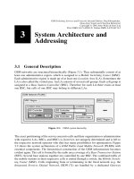
A newer technology that shows promise is
flash-based FPGAs. These devices are essen-
tially the same as SRAM-based devices,
except that they use flash EPROM bits for
programming. Flash EPROM bits tend to be
small and fast. They are nonvolatile like anti-
fuse, but reprogrammable like SRAM.
Flash-based FPGA routing is shown in Figure
3.10.
Table 3.1 summarizes how SRAM and
antifuse programming technologies compare.
3.8 Emulating and Prototyping ASICs
Designers can also use FPGAs in places where an ASIC will eventually be used.
For example, designers may use an FPGA in a design that needs to get to market
quickly at a low initial development cost. Later, they can replace the FPGA with
an ASIC when the production volume increases, in order to reduce the part cost.
Most FPGA designs, however, are not intended to be replaced by an ASIC.
Table 3.1 Comparison of FPGA programming technologies.
SRAM Antifuse
Volatile Yes No
In-system programmable Yes No
Speed Fast Somewhat faster
Power consumption Higher Lower
Density High High
IP security No Yes
Embedded RAM Yes No
Flash
bit
a) mux routing
Flash
bit
b) transistor
routing
Figure 3.10 FPGA routing using
flash bits
Please purchase PDF Split-Merge on www.verypdf.com to remove this watermark.
46 Emulating and Prototyping ASICs
Reconfigurable Computing
An interesting concept, reconfigurable computing, has been floating around universities for the past
decade or so and has been the subject of a number of research papers. In recent years, some compa-
nies have begun offering different variations of the concept in actual products. Essentially, the concept
behind configurable computing is that computations can be performed much faster using special pur-
pose hardware than using general-purpose hardware (a processor) running software. Therefore, general
computing could be sped up significantly if hardware could be dynamically reconfigured to act as a spe-
cialized coprocessors. Obviously, SRAM-based FPGAs would be an ideal implementation for this hard-
ware.
The first, and most difficult, obstacle to reconfigurable computing is that a compiler must be able to
partition a general-purpose computer program into software and hardware functionality by extracting
the algorithms that can be implemented in hardware. It must then compile the algorithm code into an
FPGA design. Synthesis programs have a difficult enough time doing the same operation using a hard-
ware description language, which is designed specifically for this use. And a synthesis program doesn’t
need to partition the code between hardware and software — all of the HDL code represents hard-
ware. Because the process is so difficult, synthesis programs restrict the HDL code to a specific coding
style to make the job easier. Also, hardware designers still need to set switches within comments in
the code and change settings of the synthesis program, in order to get usable results. And after all of
this, the designer often needs to tweak the HDL code to fit the design into the FPGA and to meet the
required performance criteria.
The second obstacle is the relatively long time required to load a new design into an FPGA. Unless
companies can speed up this process, reconfigurable computing will be limited to algorithms that are
repeated in a loop in the code, so that the overhead of reprogramming the FPGA is compensated by
the number of times the hardware algorithm is executed.
As companies come to market with reconfigurable computing solutions, they have been taking a more
practical approach than the “Holy Grail” described above. Some of the solutions include libraries of
algorithms that have already been developed, tested, and synthesized and that can be called from soft-
ware. Other companies have created new programming languages that combine the flexibility of C++,
for example, with an HDL. Such languages make it easier for compilers to partition and synthesize the
code. The disadvantage is that these a new non-standard languages represent a particularly challenging
learning hurdle, becuase they require a knowledge of both software and hardware design techniques.
(Continued on page 47.)
Please purchase PDF Split-Merge on www.verypdf.com to remove this watermark.
Emulating and Prototyping ASICs 47
FPGAs tend to be used where programmability, up-front cost, and time to mar-
ket are more important than part cost, speed, or circuit density.
There are two methodologies in integrated circuit chip design where FPGAs
are being used to assist in the development of chips and the development of soft-
ware that depends on these chips. These methodologies are known as emulation
and prototyping.
3.8.1 Emulation
Several companies provide standalone hardware boxes for emulating the func-
tion of an ASIC or a custom integrated circuit. These hardware emulators can be
programmed with a design for a chip. Once programmed, the emulator can be
physically connected to a target circuit board where the chip would normally be
connected. Then, the entire target system can be run as if the chip were actually
available and functioning. You can then debug the design using real world hard-
ware and real world software. You can stop and start the hardware emulator in
order to examine internal nodes of the design. You can capture waveform traces
of internal and I/O signals for debugging. You can make changes to the design to
correct mistakes or to improve performance, before the design is committed to
silicon.
I believe that these practical, but limited solutions will eventually produce a real-world product that
will have some use in specific areas. The progress of reconfigurable computing will probably paral-
lel that of silicon compilation. In the early 1980s, some companies, such as Silicon Compilers, Inc.,
were touting the ability to go directly from a schematic diagram to a chip layout. The problem turned
out to be bigger than these advocates thought; the algorithms needed were much more complex
than they originally believed, and the computing power to execute the algorithms just wasn’t avail-
able yet at a reasonable cost. So these companies all folded, but not without first producing corpo-
rate offspring and cousins, such as Synopsys Corporation, that decided they could tackle a much
easier problem and still provide a solution that engineers could use. Their solution was software
synthesis — software that could produce a gate level description from an RTL level description.
This much less ambitious but much more achievable solution was a great success and may still
eventually lead to the ultimate solution of silicon compilation. Many successful new products in the
engineering design automation (EDA) industry follow this same trajectory. An ambitious first prod-
uct fails, leading others to attempt smaller, less costly, more achievable products that succeed. In
the same way, I believe, restricted solutions to reconfigurable computingwill make their way into
the marketplace and be successful, and eventually lead to more and more complex implementa-
tions.
Please purchase PDF Split-Merge on www.verypdf.com to remove this watermark.
48 Chapter 3: Field Programmable Gate Arrays (FPGAs)
For example, if you are designing a new microprocessor, you could load the
microprocessor design into a hardware emulator, plug the emulator into a target
personal computer motherboard, and actually boot Linux or any other operat-
ing system. You could even run real applications. Of course, a hardware emula-
tor runs at a fraction of the speed of the final chip, but it affords a form of
testing that is otherwise not possible, except with prototyping.
Different hardware emulators from different manufacturers have different
internal architectures. Many of them, though, use large sets of FPGAs to emu-
late the chip design, because FPGAs allow users to easily load and modify
designs, stop the design while it is in the system, and easily examine internal
nodes and external I/O.
3.8.2 Prototyping
As FPGAs become faster and denser, and ASICs become larger, prototyping has
become an important alternative to emulation. Prototyping involves loading a
chip design into one or more FPGAs. If the chip design fits into a single FPGA,
the FPGA can be plugged into a socket or soldered into a target circuit board
where the final chip will ultimately go. The board can then be powered up and
tested using real data. If the design cannot fit into a single FPGA, a board can be
designed that contains several FPGAs into which the chip design is partitioned.
Companies now provide software that will automatically partition a chip design
into multiple FPGAs.
These design-specific FPGA prototypes generally run faster than a hardware
emulator because they do not have the overhead required for a general purpose
machine, and there are fewer FPGAs — only the exact number required to
implement your chip design. On the other hand, they do not have the built-in
diagnostic capabilities of a hardware emulator, and they do not come with
application engineers to support you. FPGA prototypes are generally cheaper
than hardware emulators, but you must do all of the work, including partition-
ing the design, designing the board to hold the FPGAs, and designing whatever
debug capabilities you require.
3.9 Summary
This section summarizes the various aspects of FPGAs that we have learned in
this chapter. This section also provides a list of factors to use when deciding
whether to choose a CPLD or FPGA for your design.
Please purchase PDF Split-Merge on www.verypdf.com to remove this watermark.
Summary 49
3.9.1 FPGA Selection Criteria
Knowledge of the internal architecture of FPGAs and the semiconductor tech-
nologies used to implement the programmable elements is critical for consider-
ing which FPGA to use in your design. When making that decision, you should
take into account the following architectural and technological issues:
• Configurable logic blocks — Although most FPGAs have similar logic blocks,
there are differences, for example, in the number of flip-flops and the width
of the lookup tables. Try to find a CLB architecture that fits your design. If
your design has wide combinatorial functions, choose an FPGA using CLBs
with large numbers of inputs. If your design has many pipelined stages, you
will prefer CLBs with several flip-flops. Newer architectures are always being
developed that fit the needs of specific types of designs, such as digital signal
processing.
• The number of CLBs in the device — This will determine how much logic the
device can hold and how easily your design will fit into it.
• The number and type of I/O pins — Obviously, the FPGA will need to sup-
port the number of I/O pins in your design. Also, determine how many of
these are general purpose I/O and how many are reserved for special func-
tions such as clock input, master reset, etc.
• The number of clock input pins — Clock signals can be driven only into par-
ticular pins. If your design has several clock domains (i.e., sections driven by
separate clocks), you will need an FPGA that has that many clock input pins.
• Embedded devices — Does your design interface with devices such as a
microcontroller or a PLL? Many FPGAs now incorporate specialized func-
tions like these, which will make your job much easier and allow you to inte-
grate more devices into a single FPGA.
• Antifuse vs. SRAM programming — Which technology makes sense for your
design? Do you need the speed, low power, nonvolatility, and security of an
antifuse device, or do you need the reprogrammability of an SRAM-based
device?
• Emulating and prototyping ASICs — FPGAs can be found in off-the-shelf
hardware emulators for testing the design of an ASIC in a real-world target
before it goes to silicon. Or you can use FPGAs to create your own custom
prototype of an ASIC for the same kind of pre-silicon real-world testing.
Other issues must be taken into account for all programmable chips that you
intend to use in your design. For a list of these general issues, refer to Section 4.2
about the chip specification.
Please purchase PDF Split-Merge on www.verypdf.com to remove this watermark.
50 Chapter 3: Field Programmable Gate Arrays (FPGAs)
3.9.2 Choosing Between CPLDs and FPGAs
Choosing between a CPLD and an FPGA will depend on the requirements of
your project. Table 3.2 shows a summary of the characteristics of each type of
programmable device. You will notice that I use fuzzy terms like “low,”
“medium,” and “high” for some of the characteristics. People often want me to
give a definitive answer on, for example, the number of gates in a typical CPLD
or the cost of a typical FPGA. Because these numbers change so quickly, they are
wrong as soon as they leave my lips (or in this case when they reach print). For
that reason, I prefer to give relative characteristics that will still be correct for a
while after I give them.
Table 3.2 CPLDs vs. FPGAs
CPLD FPGA
Architecture PAL-like Gate array–like
Speed Fast, predictable Application dependent
Density Low to medium Medium to high
Interconnect Crossbar Routing
Power consumption High per gate Low per gate
Please purchase PDF Split-Merge on www.verypdf.com to remove this watermark.
Exercises 51
Exercises
1. What does the term FPGA mean?
(a) Formally Programmable Gate Array
(b) Field Programmable Gate Array
(c) Finite Programmable Gate Array
2. Select all of the parts of a typical FPGA architecture.
(a) Configurable logic blocks
(b) Configurable program blocks
(c) Programmable interconnect
(d) Configurable I/O blocks
(e) Programmable address decode blocks
3. Select TRUE or FALSE for the following statements:
(a) TRUE or FALSE: Configurable I/O blocks contain flip-flops on the inputs to
enable a designer to reduce the hold-time requirement for the inputs.
(b) TRUE or FALSE: Configurable I/O blocks contain flip-flops on the outputs to
enable the designer to decrease the clock-to-output times of the outputs.
(c) TRUE or FALSE: FPGA programmable interconnect consists of lines that start
at one end of the chip and continue to the other end to enable all CLBs to be
connected.
(d) TRUE or FALSE: Programmable switches inside the chip allow the connection
of CLBs to interconnect lines.
(e) TRUE or FALSE: Programmable switches inside the chip allow the connection
of interconnect lines to each other and to the switch matrix.
(f) TRUE or FALSE: Each flip-flop in an FPGA has its own unique clock line and
clock buffer to reduce skew.
(g) TRUE or FALSE: Any input to an FPGA can be used for the clock input.
(h) TRUE or FALSE: Antifuse FPGAs use an industry standard process.
(i) TRUE or FALSE: Antifuse technology is faster than SRAM technology, in theory.
(j) TRUE or FALSE: SRAM FPGAs are more common than antifuse FPGAs.
Please purchase PDF Split-Merge on www.verypdf.com to remove this watermark.
52 Chapter 3: Field Programmable Gate Arrays (FPGAs)
4. Select all potential advantages of embedded devices
(a) Reduced board area
(b) Reduced power consumption
(c) Reduced cost
(d) Increased system speed
(e) No need to design and test the embedded device
5. Select TRUE or FALSE for each of the following statements about SRAM-based
FPGAs and antifuse FPGAs:
(a) SRAM-based FPGAs are based on an industry standard technology.
(b) In theory, SRAM-based FPGAs are much slower than antifuse FPGAs.
(c) Antifuse FPGAs retain their programming after being powered off and then on
again.
(d) Antifuse FPGAs can be erased and reprogrammed.
(e) SRAM-based FPGAs can be erased and reprogrammed.
(f) In practice, SRAM-based FPGAs are much slower than antifuse FPGAs.
(g) SRAM-based FPGAs are programmed using high voltages.
(h) Antifuse FPGAs are programmed using high voltages.
6. Clock trees are designed for (select one)
(a) Low speed and low power
(b) Small delay and low power
(c) Small delay and low skew
(d) Low inductance and low skew
(e) Low power and high density
Please purchase PDF Split-Merge on www.verypdf.com to remove this watermark.
Exercises 53
7. Fill in the following table by selecting the correct attributes of CPLDs and FPGAs
from the choices in each box.
CPLD FPGA
Architecture
Gate array–like
PAL-like
PROM-like
Gate array–like
PAL-like
PROM-like
Density
Low to medium
Medium to high
Low to medium
Medium to high
Speed
Fast and predictable
Slow and predictable
Application dependent
Fast and predictable
Slow and predictable
Application dependent
Interconnect
Bonded
Routing
Crossbar
Bonded
Routing
Crossbar
Power
consumption
Negligible
Low per gate
High per gate
Negligible
Low per gate
High per gate
Please purchase PDF Split-Merge on www.verypdf.com to remove this watermark.
54 Chapter 3: Field Programmable Gate Arrays (FPGAs)
This Page Intentionally Left Blank
Please purchase PDF Split-Merge on www.verypdf.com to remove this watermark.
55
Chapter 4
Universal Design Methodology
for Programmable Devices
(UDM-PD)
This chapter describes the Universal Design Methodology for programmable
devices. This method, based on my years of experience designing many types of
programmable devices for small and large companies in different industries, lays
out the entire process for designing a programmable device. Following the UDM
guarantees that you will not overlook any steps and that you will have the best
chance of creating a chip that functions correctly in your system.
Objectives
In this chapter, using Universal Design Methodology as a reference model, you
will learn what steps are necessary to create working, reliable chips that func-
tion correctly in your system. The first section of this chapter explains UDM and
specifically UDM-PD for programmable devices. The following sections detail
each step of the design process and how it relates to the method. Reading this
chapter will help you:
• Understand the UDM and UDM-PD methods.
In this chapter
• UDM and UDM-PD
• Specification and
specification review
• Devices and tools
• Design, simulate, and review
• Testing
Please purchase PDF Split-Merge on www.verypdf.com to remove this watermark.
56 Chapter 4: Universal Design Methodology for Programmable Devices
• Discover the importance of writing a specification and performing a specifi-
cation review.
• Learn how to choose appropriate programmable devices and software tools
based on your specification.
• Recognize the issues to consider when synthesizing your design.
• Understand the need for proper simulation, review, and testing techniques
during and after the process.
4.1 What is UDM and UDM-PD?
After years of designing circuit boards, ASICs,
FPGAs, and CPLDs for a large number of
companies, I noticed that engineers rarely fol-
lowed a complete methodology, i.e., a com-
plete set of standard procedures and steps. In
many cases, companies simply assumed their
engineers somehow knew what to do next —
and the outstanding engineers often did. If the
methodology was in some brilliant engineer’s
head, though, when that engineer left the com-
pany the methodology left, too, leaving the
company to rediscover and redevelop the
knowledge through costly trial-and-error. In
those companies that had established proce-
dures, the process documentation often con-
sisted of scattered notes and files; rarely was
the documentation compiled in one place.
Even in companies that followed a defined
procedure, often parts of the procedure were
not well understood or completely imple-
mented. For example, a company might
emphasize the design process and not under-
stand the testing process.
Eventually, as a consultant going from company to company, I decided I
needed a methodology that I could take with me for each new design. It would
have to be one that applied universally to large and small companies in any
industry. Rather than being a method that described very specific steps, it would
need to be a methodology that could be generally applied to different designs. I
called this methodology the Universal Design Methodology. As technology
changed, the methodology was adapted. I did find that different types of devices
Write a Specification
Specification Review
Choose Chip and Tools
Design
Simulate
Design Review
Synthesize
Simulate, Formal Verification
Final Review
System Integration and Test
Ship product!
Verification
Place and Route
Figure 4.1 Design Flow
Please purchase PDF Split-Merge on www.verypdf.com to remove this watermark.
Writing a Specification 57
required slightly different methodologies. ASICs and printed circuit boards
required slightly different methodologies than FPGAs and CPLDs. The method-
ology described here is specifically for programmable devices, and I call it
UDM-PD.
4.1.1 The Goals of UDM
The goals of the Universal Design Methodology are these:
• Design a device that
• Is free from manufacturing defects
• Works reliably over the lifetime of the device
• Functions correctly in your system
• Design this device efficiently, meaning
• In the least amount of time
• Using the least amount of resources, including personnel
• Plan the design efficiently, meaning
• Create a reasonable schedule as early in the process as possible
• Know all necessary resources up front and allocate them as early in the pro-
cess as possible
4.1.2 The Design Flow of UDM-PD
UDM-PD specifies a design flow that enables you to reach the UDM design
goals when designing a programmable device. The design flow consists of the
steps shown in Figure 4.1. Each particular design will have slight variations in
the specifics of each step, but essentially the steps will be the same. By under-
standing the entire flow before the project begins, you will be able to meet goal
number three, a better understanding of how to schedule and allocate resources
for the development process.
4.2 Writing a Specification
I cannot overstate the importance of a specification. A specification is an abso-
lute must, especially as a guide for choosing the right device and the right tech-
nology and for making your needs known to the vendor. All too often I’ve been
called in to consult for a company, and when I ask to see the spec, I am told that
it doesn’t exist. Or I am given a copy of a spec, but told to ignore it because it is
not up to date.
A specification allows each engineer to understand the entire design and his
piece of it. It allows the engineer to design the correct interface to the rest of the
Please purchase PDF Split-Merge on www.verypdf.com to remove this watermark.
58 Chapter 4: Universal Design Methodology for Programmable Devices
chip. It also saves time and thus cost, and helps avoid misunderstanding. There
is no excuse for not having a written specification.
A specification should include the following information:
• External block diagram showing how the chip fits into the system
• Internal block diagram showing each major functional section
• Description of the I/O pins, including:
• Output drive capability
• Input threshold level (e.g., CMOS, TTL, ECL, etc.)
• Timing estimates, including:
• Setup and hold times for input pins
• Propagation times for output pins
• Clock cycle time
• Gate count estimate
• Package type
• Power consumption target
• Price target
• Test procedures
It is very important to understand that the specification is a living document.
Many sections will have best guesses in them, but these will become more accu-
rate as the chip is being designed. Engineering problems will arise that will
require compromises in functionality. Market changes may require changes in
the specification. All of these decisions must use the specification as an
up-to-date reference and all subsequent changes must be entered into the specifi-
cation.
4.2.1 External Block Diagram
The external block diagram must show how the device fits into the system. This
diagram will help describe the overall functionality of the device and will be a
good reference for the system designers, PC board designers, designers of other
chips in the system, and software developers.
4.2.2 Internal Block Diagram
The internal block diagram will be the starting point for the behavioral descrip-
tion of the device. As the behavioral HDL code changes, these changes must be
incorporated into the internal block diagram. As other factors necessitate
changes in the internal block diagram, these changes can also be incorporated
easily into the behavioral HDL code.
Please purchase PDF Split-Merge on www.verypdf.com to remove this watermark.
Writing a Specification 59
4.2.3 Description of the I/O Pins
The device that you choose is often restricted by the requirements of the I/O
pins. The number of pins will help decide which package you will need. The
electrical characteristics of the I/O will determine which vendors and which
technologies can be used.
Life Without Specification
One of my first jobs out of school was at a large semiconductor company. Although this company
had developed some unique analog parts and a few digital parts in its history, the company was
known mostly for second sourcing “jelly beans.” That was the term for high volume, small density
parts such as TTL logic. They were able to crank them out in volume at cut-rate prices. To their credit,
they saw the future of high-end microprocessors and microprocessor peripherals that had much
lower volumes but much higher profit margins. What they didn’t understand was that these parts
were much more complex and that they accordingly required more sophisticated design methods
and procedures to produce. Instead, the engineers, project leaders, and managers at this company
continued to use the same old procedures that they had for the small jellybean parts.
The inability to recognize the need for better procedures and methodologies really doomed this
company to failure over the next decade. When other companies, like Intel, were rising to domi-
nance, this company’s revenues had a steady decline, and it was eventually bought by a much larger
company.
One example of this shortsightedness was with regard to specifications. I was recruited out of col-
lege to join the microprocessor group, which had the mandate to create complex peripheral devices,
such as memory managers and cache controllers, for the Motorola family of processors. Typically,
two or three of the best engineers in the department were assigned to a single chip. The entire doc-
umentation for the chip consisted of handfuls of schematics and lab books with handwritten notes.
Without the necessary direction or planning that these large designs required, they often dragged
on, missing schedule after schedule. Eventually, these engineers would leave the company, frus-
trated at not being able to get their designs out the door. Each time this happened, there was no
specification to turn to. It was impossible to bring a new engineer onto the project because one
third or one half of the entire specification had walked out the door in the head of the engineer who
had left. I saw all four major chip designs in this division die for exactly these reasons. Eventually,
without a single significant product in over two years, the division was closed down.
Please purchase PDF Split-Merge on www.verypdf.com to remove this watermark.
60 Writing a Specification
A Living Document
My last full-time employer (before becoming a full-time consultant) was a telecom startup. The com-
pany had lots of problems and became a great example of what not to do when designing a product or
running a company.
One of these problems should have been an early warning sign for me. I joined the company as the
main ASIC designer employee number nine and the only one with any experience designing chips. One
of the chips that needed to be designed was a simple buffer between a board and a backplane. The
logic requirements of the design were extremely simple, but the current drive requirements — 48 mA
per signal for 8 signals — was more than most ASIC vendors could produce at the time. We found that
one company, NCR Corporation, had the technology. Because the logic design was so simple, we
decided that I would produce a written specification that would be handed off to the engineers at NCR.
I would supervise their progress while I did the real design work on another important chip.
At the end of the design review, one of the engineers at the company adamantly stated that we should
demand that NCR meet the specifications that we had written. If not, he proclaimed, we would not pay
them. That would give them the incentive they needed to design the chip to our specifications. I said
that it made more sense for us to work with them to understand any issues that might arise. If NCR
couldn’t meet the specification, we would work with them to get the best results possible and see how
we could change the specifications, and the specifications of our system, to get the best results possi-
ble. He was insistent. We argued for some time, the other engineers at the review sitting quietly and
uncomfortably. Finally, I told him that I agreed. If NCR couldn’t manufacture the chip, we should refuse
to pay them. We would then save the $20,000 NRE fee. He smiled. I then said that we could all go
home because we had saved all that money, had no chips for our boards, no working product, no com-
pany, and no jobs. I think I then called him an idiot.
Luckily the president of this company saw my logic immediately and agreed that we should work with
NCR to produce the best product that we could. If, along the way the specifications needed to be
changed, we would change them. The written specification is not gospel; it’s a living, changing roadmap
that gets you where you’re going even if a lightning storm suddenly throws a tree along the road. You
must be specific enough to create your design, and flexible enough to make changes when necessary.
And by the way, don’t call anyone an idiot at a company meeting, even if it’s true. It makes an enemy for
a long time — an enemy who can take revenge in secret ways, refuse to cooperate on important
projects, and blame you for all of his mistakes. I’m speaking from experience.
Please purchase PDF Split-Merge on www.verypdf.com to remove this watermark.
Writing a Specification 61
4.2.4 Timing Estimates
Timing estimates are needed to determine which devices, vendors, and technolo-
gies can be used. You should have a good understanding of the clock frequency
required for the design and also the setup and hold time requirements of the I/O.
(These requirements are determined by the interface between your device and
the other chips in the system.)
Remember to identify all asynchronous input signals. You can then discuss
metastability issues with the vendors that you are considering. This will give you
an idea about how well the vendor has characterized their devices and the tech-
nical proficiency of their own engineers — a definite factor in choosing a vendor.
4.2.5 Gate Count Estimate
As you gain experience designing programmable devices, estimating gate counts
will become easier. For your first few designs, talk to the various vendors you
are considering. They will be able to help you construct reasonable estimates
and determine which of their devices are appropriate for your design.
4.2.6 Package Type
Package type is often a very large percentage of the entire cost of an FPGA.
Understand the package options offered by different vendors. Also, you will
need to understand the capabilities of your PC board layout designers and fabri-
cation facilities to work with the different package types.
4.2.7 Power Consumption Target
Be certain you understand the variables that affect the device’s power consump-
tion. You must also understand how the device’s operation will affect overall
board and system power consumption. Finally, whoever is designing or choosing
the power supply will need to know how much power, typical case and worst
case, each chip in the system will require.
4.2.8 Price Target
For most projects, you will need a realistic price target. This target can help you
determine the necessary tradeoffs between pin count, functionality, speed, pack-
age type, and other factors.
4.2.9 Test Procedures
Test procedures must be known at a very early stage of the design flow. Too
often, design teams leave test procedures for the end of the design flow at which
time they discover that the device cannot be tested completely or accurately. If
the tests require software, the software team must begin planning the tests very
Please purchase PDF Split-Merge on www.verypdf.com to remove this watermark.
62 Writing a Specification
The Correct Way To Calculate Power Consumption
Engineers often ask me about power calculations for circuit boards or systems. When they add up the
worst-case power consumption numbers for all of the parts in the system, they end up with a number
so large that it seems unreasonable. They can’t justify designing in a power supply that large, or the
necessary cooling needed to get the predicted temperature down to something acceptable. When they
put the system together, the power numbers are often much closer to the typical power consumption
numbers than the worst-case power consumption numbers. Many engineers simply shrug or apply
some rule of thumb such as cutting the worst-case power number by a factor of two. Some engineers
are bothered by the fact that the numbers are off. Some know the secret to correctly calculating
worst-case power consumption, and I’m about to reveal that secret to you.
The power numbers which manufacturer’s report for individual components are statistical numbers. The
best case and worst case numbers are usually values three sigma in either direction from the mean
(looking at a standard Bell curve). In other words, there is an insignificant probability that the power
consumption is more than the worst-case numbers or less than the best-case numbers. If you treat the
individual components statistically, you should treat the entire circuit board or system statistically.
Therefore, to get a realistic number of the best-case, typical-case, and worst-case power consumption
for a system, use the following formulae (which are standard formulae for the mean and standard devi-
ation of a discrete random variable):
Minimum system power
Typical system power
Maximum system power
where
is the minimum power of component i
is the typical power of component i
is the maximum power of component i
Using the formula for worst-case maximum power consumption of a system, you’ll find that the more
components in the system, the closer this maximum power is to the typical power. And this makes
sense. For a system with many components, it is more likely that most of them are running under typi-
cal conditions and only a few of them are running at worst-case conditions.
P
min
P
i typ,
∑
P
i typ,
P
i min,
–()
∑
2
–=
P
typ
P
i typ,
∑
=
P
max
P
i typ,
∑
P
i max,
P
i typ,
–()
∑
2
+=
P
i min,
P
i typ,
P
i max,
Please purchase PDF Split-Merge on www.verypdf.com to remove this watermark.
Specification Review 63
early, and they must have input into the hardware design so that testability is
built in from the beginning.
4.3 Specification Review
At the end of the specification phase, it is very important to have a design
review. As many people as are interested should take part in this review, because
this specification is the basis for the entire chip. You want to know right now if
anything is wrong or has been left out. Invite people from all departments who
are specifically involved with the chip and the system, including marketing,
sales, software, applications, etc.
4.4 Choosing Device and Tools
Once a specification has been written, the design team can use it to find the best
vendor with a technology and price structure that best meets their requirements.
They can also choose tools to work well together and with the device and tech-
nology they have chosen.
One important case in point for choosing the device and tools at this early
stage is that of synthesis. The selection of a synthesis tool will determine the
coding style for the RTL HDL. A specific coding style is necessary because syn-
thesis tools cannot do a good job if they must handle too many code possibili-
ties. For example, there are many ways to code state machines. If the synthesis
tool needs to understand each possible way, it becomes more complex and thus
more error prone. To avoid problems like this, synthesis tool vendors specify
coding guidelines guaranteeing that their tools will recognize the structures you
are designing and synthesize them correctly to gate level descriptions.
4.5 Design
When designing the chip, remember to design according to the rules that are dis-
cussed in detail in Chapter 5. These are
• Use top-down design
• Work with the device architecture
• Do synchronous design
• Protect against metastability
• Avoid floating nodes
• Avoid bus contention
Please purchase PDF Split-Merge on www.verypdf.com to remove this watermark.
64 Design
A Testing Horror Story
If you’re frightened easily, don’t read further. Some years ago I was called into a small startup company
that was designing medical imaging equipment. The founder of the company, an engineer, had been
kicked out by the investors. The senior members of the engineering team, maybe three or four people,
left with him. The company called me in as a consultant to help them figure out why the hardware they
had didn’t work. Through a painful reverse engineering process (the fleeing engineers had left no docu-
mentation), I found a slew of reliability problems that I corrected one by one. At that point, although we
had a working board covered by blue wires, I suggested that we redesign the board. The company
agreed. I then submitted a plan, including a test plan, whereby the software engineers would write
code to test the hardware.
When the board had been redesigned and it came back from fabrication and assembly, I went to the
software engineers to get the code to begin testing. The software engineers told me that the new Vice
President of Engineering had changed all of the priorities so that the test code was dead last on the list.
I went to the VP’s office for an explanation. He explained that getting the next round of funding was
contingent on getting a beta site for our system. If we had a system working in a hospital, then we
could get funding to keep going. Otherwise the company would be out of business. How could we get
the system working, I asked, if we couldn’t test the hardware. Wouldn’t it be better if we put a working
system into a beta site than a nonworking one? He told me that he trusted my abilities so much that he
was sure my hardware worked perfectly. I told him that I appreciated his confidence, but even I don’t
deserve that kind of responsibility.
The story gets worse. I decided to write some software tests at that time. It was difficult because I
didn’t understand all of the software running on this system. I was able to get a test running that looped
random data throughout this imaging system. Lo and behold, sometimes the data sent out came back
corrupted. I showed this to the VP and to the CEO of the company. Their response? Don’t worry. It’s
only a few pixels that get corrupted. No one will miss them. What if these pixels were enough to look
like a tumor to a doctor reviewing the image, I asked. Or worse, God forbid, they covered up a real
tumor? Don’t worry, was the reply I got again. We’ll fix it after we get the funding.
I finished up my work at the company, collected my check, and left when the contract expired. A year
later they had been turned down for more funding and went out of business.
Please purchase PDF Split-Merge on www.verypdf.com to remove this watermark.
Verification 65
4.6 Verification
Verification is a “super-phase” because it consists of several other phases of the
design process. Which exact phases that make up verification is open to argu-
ment, but generally verification can be broken into several phases, each of which
is essential to the entire process. These steps consist of
• Simulation
• Design review
• Synthesis
• Place and route
• Formal verification
The components of verification are discussed further in the following sections
and in much greater detail in Chapter 6.
4.6.1 Simulation
Simulation is an ongoing process; some kind of simulation will be performed as
part of nearly every stage of the design process. Small sections of the design
should be simulated separately before hooking them up to larger sections, as
described in Chapter 7. There will be many iterations of design and simulation
in order to get the correct functionality.
4.6.2 Design Review
Once design and simulation are finished, another design review must take place
so that other engineers can check the design. It is important to get other engi-
neers to look over the simulations. At this stage, they should be looking for
missed details and improper assumptions. This is one of the most important
reviews because only with correct and complete simulation will you know that
the chip will work correctly in your system.
In addition to the chip design team, you should invite engineers who were
not involved in the actual chip design to this review. Often, the chip designers
will inadvertently make assumptions that outsiders would question. These out-
siders can also suggest corner cases that were not already simulated that will
often uncover additional problems in the design.
4.6.3 Synthesis
The next step is to synthesize the chip. This involves using synthesis software to
optimally translate your RTL design into a gate level design that can be mapped
to logic blocks in the FPGA. This may involve specifying switches and optimiza-
tion criteria in the HDL code, or playing with parameters of the synthesis soft-
ware in order to ensure good timing and utilization.
Please purchase PDF Split-Merge on www.verypdf.com to remove this watermark.
66 Chapter 4: Universal Design Methodology for Programmable Devices
After synthesis, the chip must be resimulated using the gate level output of
the synthesis tool. If everything has gone well up to this point, the gate level sim-
ulation results will agree with the RTL results. Another possibility is to use a
formal verification tool that will logically compare the RTL description to the
gate level description. Whichever method is used, the design team will need to
address any discrepancies. Discrepancies discovered at this stage often are the
result of processing RTL code that doesn’t conform to the style rules expected
The Need For Specification Reviews
After about two years at the large semiconductor company that employed me right out of school, I
was given my first responsibility as a project leader designing a dual universal asynchronous receiver
transmitter, or dual UART. I had another engineer reporting to me, and I was pretty excited about
this. The project had some visibility within the division and people would periodically stop me to find
out about my progress. What confused me, though, was that different people from different depart-
ments had different ideas about what I was designing. One day, a sales person would ask me about
the quad UART. I would explain that it was a dual UART. They would say something about customers
needing four, not two, on a chip. Another day, a marketing person would ask me about the UART. I
would explain that it was a dual UART. They would say something about the customers who had
been waiting for a UART to drop into their existing systems. When I mentioned a quad UART to the
people in semiconductor processing, they would laugh, saying it wasn’t possible to put a device that
large on a single die and still fit into an existing package.
I finally decided to hold a specification review — something that I then realized should have been
held at the beginning of the project. I invited the managers from engineering, sales, marketing, test-
ing, and production. In going over the specifications I found that the product I was in charge of met
no one’s expectations and could probably not be sold. Had we known this at the beginning, we
could have modified the specifications or spent our energies on a product that would actually make
money.
Afterwards, I was told to continue working on the chip, despite the fact that we couldn’t sell it,
because we had already announced it and wanted to show that at least once we could produce
something we had publicized. Demoralized about my new project, I continued with the company
long enough to get the chip design on the right track and put it in the hands of my colleague. The
design was fully documented, a rarity at this company, and I left to find other work. Later I found out
that the design was cancelled right before production because someone higher up found out that no
one really wanted to buy it.
Please purchase PDF Split-Merge on www.verypdf.com to remove this watermark.
Verification 67
by the synthesis tool. Correcting these problems is usually a straightforward
matter of rewriting the code in the correct format.
4.6.4 Place and Route
The next step is to lay out the chip, resulting in a real layout for a real chip. This
involves using the vendor’s software tools to place various functions into the
available blocks in the device and to route the blocks together. The software will
figure out the bits needed to program the chip to implement the design. If you
cannot successfully place the design into the device and route it, you may need
to tweak the design. In some cases, you will need to make radical changes, such
as eliminating some functionality or using a larger device. If you have followed
all of the procedures outlined in this book, the chances of a major problem at
this stage, resulting in a major design change, will be minimized.
Once the place and route is successful, the design team must perform timing
analysis. The timing analysis will determine whether the designmeets the timing
goals. Typically, the design team will need to redesign and resimulate certain
paths in order to get the correct timing. In some cases, they will need to change
functionality, or they will need to change the timing specifications of the chip, in
order to get the design to work.
4.6.5 Resimulation and Formal Verification
At this stage, the design team must check the results of synthesis to make sure
that the RTL design that was fully simulated is functionally equivalent to the
gate level design that was produced after synthesis. In some cases, it may also be
necessary to show that the configuration of the programmable device behaves
identically to the RTL description. There are two ways to do this: by resimulat-
ing the lower level design or by using formal verification. In some cases, both
techniques can be used for further certainty.
Resimulation
The most common method of determining that the input circuit and the final cir-
cuit are correct is to resimulate the final circuit using all of the tests that were
used to simulate the original circuit. These tests are called regression tests. The
results of both circuits should be identical for each clock edge.
Equivalency Checking
The formal verification that takes place at this stage is known as equivalency
checking. This kind of formal verification involves a software tool that com-
pares the RTL design with the gate level design created by the synthesis soft-
ware, or possibly even compares it with the resulting configuration of the FPGA
Please purchase PDF Split-Merge on www.verypdf.com to remove this watermark.
68 Chapter 4: Universal Design Methodology for Programmable Devices
or CPLD. This software performs a mathematical comparison of the functional-
ity of both circuits in order to confirm that both circuits will operate correctly.
4.7 Final Review
The final review of the chip should be a formality at this point. If the design
team has followed all of the other steps and the other reviews have taken place,
this review should be a simple sign-off that verifies that the design has been
coded, simulated, synthesized, laid out and routed, and is now ready to go into
the system.
4.8 System Integration and Test
For a one-time programmable device such as most CPLDs or an antifuse FPGA,
you simply program the device at this time, and you immediately have your pro-
totypes. For a reprogrammable chip, such as an SRAM-based FPGA, you place
a blank chip into your system, and the system programs it during power up. In
either case, you have the responsibility to determine that the entire system, with
your programmable device, actually works correctly.
If you have followed the procedure up to this point, chances are very good
that your system will perform correctly with only minor problems. The design
team can often work around these minor problems by modifying the system or
changing the system software. The team needs to test and document these prob-
lems so that they can fix them on the next revision of the chip. System integra-
tion and system testing is necessary at this point to ensure that all parts of the
system work correctly together.
When the chips are put into production, the production process should
include some sort of burn-in test that continually tests the system over some
long amount of time. If a chip has been designed correctly, it will only fail
because of marginal physical defects that will usually show up with this kind of
stress testing.
4.9 Ship Product!
At this point you are done. It is time to ship your product and take that long
awaited vacation.
Please purchase PDF Split-Merge on www.verypdf.com to remove this watermark.