Tài liệu FAILURE CONSIDERATIONS P4 pptx
Bạn đang xem bản rút gọn của tài liệu. Xem và tải ngay bản đầy đủ của tài liệu tại đây (1.88 MB, 31 trang )
hypothesis
may be
written
as
follows:
If a
design limit
of
creep strain
8
D
is
specified,
it is
predicted
that
the
creep strain
8
D
will
be
reached when
ST-=!
(!8-78)
i=l
L
1
where
t
t
=
time
of
exposure
at the rth
combination
of
stress level
and
temperature
L
1
=
time required
to
produce creep strain
8
D
if
entire exposure were held constant
at the
/th
combination
of
stress level
and
temperature
Stress rupture
may
also
be
predicted
by
(18.78)
if the
L
1
values correspond
to
stress rupture. This
prediction technique gives relatively accurate results
if the
creep deformation
is
dominated
by
stage
II
steady-state
creep behavior. Under other circumstances
the
method
may
yield predictions
that
are
seriously
in
error.
Other cumulative creep prediction techniques that have been proposed include
the
time-hardening
rule,
the
strain-hardening rule,
and the
life-fraction
rule.
The
time-hardening rule
is
based
on the
assumption that
the
major
factor
governing
the
creep rate
is the
length
of
exposure
at a
given tem-
perature
and
stress level,
no
matter what
the
past history
of
exposure
has
been.
The
strain-hardening
rule
is
based
on the
assumption that
the
major
factor
governing
the
creep rate
is the
amount
of
prior
strain,
no
matter what
the
past history
of
exposure
has
been.
The
life-fraction
rule
is a
compromise
between
the
time-hardening rule
and the
strain-hardening rule which accounts
for
influence
of
both
time history
and
strain history.
The
life-fraction
rule
is
probably
the
most accurate
of
these prediction
techniques.
18.7
COMBINED
CREEP
AND
FATIGUE
There
are
several important high-performance applications
of
current interest
in
which conditions
persist that lead
to
combined creep
and
fatigue.
For
example,
aircraft
gas
turbines
and
nuclear power
reactors
are
subjected
to
this combination
of
failure
modes.
To
make matters worse,
the
duty cycle
in
these applications might include
a
sequence
of
events including
fluctuating
stress levels
at
constant
temperature,
fluctuating
temperature
levels
at
constant stress,
and
periods during which both stress
and
temperature
are
simultaneously
fluctuating.
Furthermore, there
is
evidence
to
indicate that
the
fatigue
and
creep processes interact
to
produce
a
synergistic response.
It
has
been observed that interrupted stressing
may
accelerate, retard,
or
leave
unaffected
the
time
under stress required
to
produce stress rupture.
The
same observation
has
also been made with respect
to
creep
rate. Temperature cycling
at
constant stress level
may
also produce
a
variety
of
responses,
depending
on
material properties
and the
details
of the
temperature cycle.
No
general
law has
been
found
by
which cumulative creep
and
stress rupture response under
temperature cycling
at
constant stress
or
stress cycling
at
constant temperature
in the
creep range
can
be
accurately predicted. However, some recent progress
has
been made
in
developing
life
prediction
techniques
for
combined creep
and
fatigue.
For
example,
a
procedure sometimes used
to
predict
failure
under combined creep
and
fatigue
conditions
for
isothermal cyclic stressing
is to
assume that
the
creep
behavior
is
controlled
by the
mean stress
cr
m
and
that
the
fatigue
behavior
is
controlled
by
the
stress amplitude
cr
a
,
with
the two
processes combining linearly
to
produce failure. This approach
is
similar
to the
development
of the
Goodman diagram described
in
Section
18.5.4
except that instead
of
an
intercept
of
cr
u
on the
cr
m
axis,
as
shown
in
Fig.
18.38,
the
intercept used
is the
creep-limited
static
stress
o~
cr
,
as
shown
in
Fig.
18.64.
The
creep-limited static stress corresponds either
to the
design limit
on
creep strain
at the
design
life
or to
creep
rupture
at the
design
life,
depending
on
which
failure mode governs.
The
linear prediction rule then
may be
stated
as
Failure
is
predicted
to
occur under combined isothermal
creep
and
fatigue
if
&„
<r
m
— + —
>
1
(18.79)
(T
N
0-
cr
An
elliptic relationship
is
also shown
in
Fig. 18.64, which
may be
written
as
Failure
is
predicted
to
occur under combined isothermal
creep
and
fatigue
if
/<r
a
\
2
/o-
m
y
M
+
M
^
1
(1880)
\(T
N
/
\cr
c
j
The
linear rule
is
usually (but
not
always) conservative.
In the
higher-temperature portion
of the
creep
range
the
elliptic relationship usually gives better agreement with data.
For
example,
in
Fig.
18.65fl
actual data
for
combined isothermal creep
and
fatigue
tests
are
shown
for
several
different
Fig.
18.64
Failure prediction diagram
for
combined creep
and
fatigue under
constant-temperature conditions.
temperatures using
a
cobalt-base
S-816
alloy.
The
elliptic approximation
is
clearly better
at
higher
temperatures
for
this alloy. Similar data
are
shown
in
Fig.
18.65&
for
2024
aluminum alloy.
Detailed
studies
of the
relationships among
creep
strain, strain
at
rupture, mean stress,
and
alternating stress
amplitude over
a
range
of
stresses
and
constant temperatures involve extensive, complex testing
programs.
The
results
of one
study
of
this
type
82
are
shown
in
Fig. 18.66
for
S-816 alloy
at two
different
temperatures.
Several other
empirical
methods have
recently
been
proposed
for the
purpose
of
making life
predictions under more general conditions
of
combined creep
and
low-cycle fatigue.
These
methods
include:
1.
Frequency-modified stress
and
strain-range
method.
83
2.
Total time
to
fracture
versus
time-of-one-cycle
method.
84
3.
Total time
to
fracture
versus number
of
cycles
to
fracture
method.
85
4.
Summation
of
damage fractions using interspersed
fatigue
with
creep
method.
86
5.
Strain-range partitioning
method.
87
The
frequency-modified
strain-range approach
of
Coffin
was
developed
by
including
frequency-
dependent terms
in the
basic
Manson-Coffin-Morrow
equation, cited earlier
as
(18.54).
The
resulting
equation
can be
expressed
as
Ae
-
AN
a
f
v
b
+
BN
c
f
v
d
(18.81)
where
the first
term
on the
right-hand side
of the
equation represents
the
elastic component
of
strain
range,
and the
second term represents
the
plastic component.
The
constants
A and B are the
intercepts,
respectively,
of the
elastic
and
plastic strain components
at
N
f
= 1
cycle
and v
—
\
cycle/min.
The
exponents
a,
b,
c,
and d are
constants
for a
particular material
at a
given temperature. When
the
constants
are
experimentally evaluated, this expression provides
a
relationship between total strain
range
Ae and
cycles
to
failure
N
f
.
The
total time
to
fracture
versus time-of-one-cycle method
is
based
on the
expression
t
f
= — = CrJ
(18.82)
v
Fig. 18.65 Combined isothermal creep
and
fatigue data
plotted
on
coordinates suggested
in
Figure
18.64.
(a)
Data
for
S-816
alloy
for
100-hr
life, where
cr
N
is
fatigue strength
for
100-hr life
and
(T
cr
is
creep rupture stress
for
100-hr
life. (From
Refs.
80 and
81.)
(b)
Data
for
2024 alumi-
num
alloy, where
o-
N
is
fatigue strength
for
life
indicated
on
curves
and
o-
cr
is
creep stress
for
corresponding time
to
rupture. (From
Refs.
80 and
82.)
Fig. 18.66 Strain
at
fracture
for
various combinations
of
mean
and
alternating stresses
in
unnotched specimens
of
S-816
alloy,
(a)
Data taken
at
816
0
C.
(b)
Data taken
at
90O
0
C.
(From Refs.
80 and
81.)
where
t
f
is the
total time
to
fracture
in
minutes,
v is
frequency
expressed
in
cycles
per
minute,
N
f
is
total cycles
to
failure,
t
c
—
1 / v is the
time
for one
cycle
in
minutes,
and C and k are
constants
for
a
particular material
at a
particular temperature
for a
particular
total
strain range.
The
total time
to
fracture
versus
number-of-cycles
method characterizes
the
fatigue-creep inter-
action
as
t
f
=
DNj
m
(18.83)
which
is
identical
to
(18.82)
if D =
C
ll(l
~
k}
and m =
k/(l
-
K).
However,
it has
been postulated
that
there
are
three
different
sets
of
constants
D and m: one set for
continuous cycling
at
varying
strain rates,
a
second
set for
cyclic
relaxation,
and a
third
set for
cyclic
creep.
The
interspersed fatigue
and
creep analysis proposed
by the
Metal Properties Council involves
the
use of a
specified combined test cycle
on
unnotched bars.
The
test cycle consists
of a
specified
period
at
constant tensile load followed
by
various numbers
of
fully
reversed strain-controlled fatigue
cycles.
The
specified test cycle
is
repeated until failure occurs.
For
example,
in one
investigation
the
specified
combined test cycle consisted
of 23
hr
at
constant tensile load followed
by
either 1.5, 2.5,
5.5,
or
22.5
fully
reversed strain-controlled fatigue cycles.
The
failure data
are
then plotted
as
fatigue
damage
fraction
versus creep damage fraction,
as
illustrated
in
Fig.
18.67.
The
fatigue damage fraction
is the
ratio
of
total number
of
fatigue cycles
N'
f
included
in the
combined test cycle divided
by the
number
of
fatigue cycles
N
f
to
cause failure
if no
creep time
were interspersed.
The
creep damage fraction
is the
ratio
of
total creep
time
t
cr
included
in the
combined test cycle divided
by the
total creep
life
to
failure
t
f
if no
fatigue cycles were interspersed.
A
"best-fit" curve through
the
data provides
the
basis
for
making
a
graphical estimate
of
life
under
combined creep
and
fatigue conditions,
as
shown
in
Fig.
18.67.
The
strain-range partitioning method
is
based
on the
concept that
any
cycle
of
completely reversed
inelastic strain
may be
partitioned into
the
following strain-range components: completely reversed
plasticity,
Ae^;
tensile plasticity reversed
by
compressive creep,
Ae
pc
;
tensile creep reversed
by
compressive
plasticity,
Ae
cp
;
and
completely reversed creep,
Ae
cc
.
The first
letter
of
each subscript
Fig.
18.67
Plot
of
fatigue damage fraction versus creep damage fraction
for 1
Cr-1
Mo-
1
A
V
rotor steel
at
100O
0
F
in
air,
using
the
method
of the
Metal Properties Council.
(After
Ref.
88,
copyright Society
for
Experimental Stress Analysis, 1973; reprinted with permission.)
in the
notation,
c for
creep
or p for
plastic deformation, refers
to the
type
of
strain imposed during
the
tensile portion
of the
cycle,
and the
second letter refers
to the
type
of
strain imposed during
the
compressive portion
of the
cycle.
The
term plastic
deformation
or
plastic
flow in
this context refers
to
time-independent
plastic strain that occurs
by
crystallographic
slip within
the
crystal grains.
The
term
creep
refers
to
time-dependent
plastic deformation that occurs
by a
combination
of
diffusion
within
the
grains together with grain boundary sliding between
the
grains.
The
concept
is
illustrated
in
Fig.
18.68.
It
may be
noted
in
Fig. 18.68
that tensile inelastic strain, represented
as AD is the sum of
plastic
strain
AC
plus creep strain
CD.
Also,
^oppressive
inelastic
strain_DA
is the sum of
plastic strain
DB
plus creep strain
BA. In
general,
AC
will
not be
equal
to DB, nor
will
CD be
equal
to BA.
However, since
we are
dealing with
a
closed hysteresis loop,
AD
does equal
DA. The
partitioned
strain
ranges
are
obtained
in the
following
manner.
89
The
completely reversed portion
of the
plastic
strain
range,
Ae^,,
is the
smaller
of the two
plastic
flow
components, which
in
Fig. 18.68
is
equal
to
DB.
Likewise,
the
completely reversed portion
of
the^reep
strain range,
Ae
cc
,
is the
smaller
of the
two
creep components, which
in
Fig. 18.68
is
equal
to CD. As can be
seen graphically,
the
difference
between
the_two_plastic
components must
be
equal
to the
difference
between
the two
creep compo-
nents,
or AC
—
DB
must equal
BA - CD.
This
difference
then
is
either
Ae
pc
or
Ae
cp
,
in
accordance
with
the
notation just
defined.
For the
case illustrated
in
Fig.
18.68,
the
difference
is
Ae
pc
,
since
the
tensile plastic strain component
is
greater
than
the
compressive plastic strain component.
It
follows
from
this discussion that
the sum of the
partitioned strain ranges will necessarily
be
equal
to the
total
inelastic strain range,
or the
width
of the
hysteresis
loop.
It
is
next assumed that
a
unique relationship exists between cyclic
life
to
failure
and
each
of the
four
strain-range components listed. Available data indicate that these relationships
are of the
form
of
the
basic
Manson-Coffin-Morrow
expression
(18.54),
as
indicated,
for
example,
in
Fig.
18.69
for
a
type
316
stainless-steel alloy
at
130O
0
F.
The
governing
life
prediction equation,
or
"interaction
damage
rule,"
is
then postulated
to be
JT
=
JT
+
JT
+
JT
+
JT
(18
-
84)
^pred
Mpp
M
pc
^CP
M
cc
where
AT
pred
is the
predicted total number
of
cycles
to
failure under
the
combined straining cycle
containing
all of the
pertinent strain range components.
The
terms
F
pp
,
F
pc
,
F
cp
,
and
F
cc
are
defined
as
=
A
Ss
=
A^
"
^
PC
^
(18.85)
^CP
^CC
F
=
—££
F =
—-
*
Ae/
~
A.
p
Fig.
18.68
Typical
hysteresis
loop.
Fig.
18.69
Summary
of
partitioned strain-life relations
for
type
316
stainless steel
at
130O
0
F
(After
Ref.
90):
(a)
pp-type
strain range;
(b)
pc-type strain range;
(c)
cp-type strain range;
(of)
cc-type strain range.
for
any
selected inelastic strain range
Ae
p
,
using information
from
a
plot
of
experimental data such
as
that shown
in
Fig.
18.69.
The
partitioned failure lives
N
pp
,
N
pc
,
N
cp
,
and
N
cc
are
also obtained
from
Fig.
18.69.
The use of
(18.84) has,
in
several
investigations,
90
-
95
shown
the
predicted lives
to
be
acceptably accurate, with most experimental results
falling
with
a
scatter band
of
±2^
of the
predicted value.
More recent investigations have indicated that improvements
in
predictions
by the
strain-range
partitioning method
may be
achieved
by
using
the
"creep"
ductility
and
"plastic"
ductility
of a
material determined
in the
actual service environment,
to
"normalize"
the
strain versus
life
equations
prior
to
using
(18.85).
Procedures
for
using
the
strain-range partitioning method under conditions
of
multiaxial loading have also been
proposed
94
but
remain
to be
verified
more
fully.
18.8
FRETTINGANDWEAR
Fretting
and
wear share many common characteristics but,
at the
same time,
are
distinctly
different
in
several ways. Basically,
fretting
action has,
for
many years, been
defined
as a
combined mechanical
and
chemical action
in
which contacting
surfaces
of two
solid
bodies
are
pressed together
by a
normal
force
and are
caused
to
execute oscillatory sliding relative motion, wherein
the
magnitude
of
normal
force
is
great enough
and the
amplitude
of the
oscillatory sliding motion
is
small enough
to
signif-
icantly restrict
the flow of
fretting
debris away
from
the
originating
site.
96
More recent definitions
of
fretting
action have been broadened
to
include
cases
in
which contacting surfaces periodically separate
and
then reengage,
as
well
as
cases
in
which
the fluctuating
friction-induced surface tractions produce
stress
fields
that
may
ultimately result
in
failure.
The
complexities
of
fretting
action have been
discussed
by
numerous investigators,
who
have postulated
the
combination
of
many mechanical,
chemical, thermal,
and
other phenomena that interact
to
produce
fretting.
Among
the
postulated
phenomena
are
plastic deformation caused
by
surface asperities plowing through each other, welding
and
tearing
of
contacting
asperities,
shear
and
rupture
of
asperities, friction-generated subsurface
shearing
stresses,
dislodging
of
particles
and
corrosion products
at the
surfaces, chemical reactions,
debris accumulation
and
entrapment, abrasive action,
microcrack
initiation,
and
surface
delam-
ination.
97
-
112
Damage
to
machine parts
due to
fretting
action
may be
manifested
as
corrosive surface damage
due to
fretting
corrosion, loss
of
proper
fit or
change
in
dimensions
due to
fretting
wear,
or
accelerated
fatigue
failure
due to
fretting
fatigue. Typical sites
of
fretting
damage include interference
fits;
bolted,
keyed, splined,
and
riveted joints; points
of
contact between wires
in
wire ropes
and flexible
shafts;
friction
clamps;
small-amplitude-of-oscillation
bearings
of all
kinds; contacting surfaces between
the
leaves
of
leaf springs;
ad all
other places where
the
conditions
of
fretting
persist. Thus,
the
efficiency
and
reliability
of the
design
and
operation
of a
wide range
of
mechanical systems
are
related
to the
fretting
phenomenon.
Wear
may be
defined
as the
undesired cumulative change
in
dimensions brought about
by the
gradual
removal
of
discrete particles
from
contacting surfaces
in
motion,
due
predominantly
to me-
chanical action.
It
should
be
further
recognized that corrosion
often
interacts with
the
wear process
to
change
the
character
of the
surfaces
of
wear particles through reaction with
the
environment. Wear
is, in
fact,
not a
single process
but a
number
of
different
processes that
may
take place
by
themselves
or
in
combination.
It is
generally accepted that there
are at
least
five
major
subcategories
of
wear
(see
p. 120 of
Ref.
113,
see
also Ref.
114),
including adhesive wear, abrasive wear, corrosive wear,
surface
fatigue
wear,
and
deformation wear.
In
addition,
the
categories
of
fretting
wear
and
impact
wear
115
"
117
have been recognized
by
wear specialists. Erosion
and
cavitation
are
sometimes considered
to be
categories
of
wear
as
well. Each
of
these types
of
wear proceeds
by a
distinctly
different
physical process
and
must
be
separately considered, although
the
various subcategories
may
combine
their
influence
either
by
shifting
from
one
mode
to
another during
different
eras
in the
operational
lifetime
of a
machine
or by
simultaneous activity
of two or
more
different
wear modes.
18.8.1
Fretting Phenomena
Although
fretting
fatigue,
fretting
wear,
and
fretting
corrosion phenomena
are
potential failure modes
in
a
wide variety
of
mechanical systems,
and
much research
effort
has
been devoted
to the
under-
standing
of the
fretting
process, there
are
very
few
quantitative design data available,
and no
generally
applicable design procedure
has
been established
for
predicting failure under
fretting
conditions.
However, even though
the
fretting
phenomenon
is not
fully
understood,
and a
good general model
for
prediction
of
fretting
fatigue
or
fretting
wear
has not yet
been developed,
significant
progress
has
been
made
in
establishing
an
understanding
of
fretting
and the
variables
of
importance
in the
fretting
process.
It has
been suggested that there
may be
more than
50
variables that play some
role
in the
fretting
process.
118
Of
these, however, there
are
probably only eight that
are of
major
importance;
they
are:
1. The
magnitude
of
relative motion between
the
fretting
surfaces.
2. The
magnitude
and
distribution
of
pressure between
the
surfaces
at the
fretting
interface.
3. The
state
of
stress, including magnitude, direction,
and
variation with respect
to
time
in the
region
of the
fretting
surfaces.
4. The
number
of
fretting
cycles accumulated.
5. The
material,
and
surface condition,
from
which each
of the
fretting
members
is
fabricated.
6.
Cyclic
frequency
of
relative motion between
the two
members being
fretted.
7.
Temperature
in the
region
of the two
surfaces being
fretted.
8.
Atmospheric environment surrounding
the
surfaces being fretted.
These variables interact
so
that
a
quantitative prediction
of the
influence
of any
given variable
is
very
dependent
on all the
other variables
in any
specific application
or
test. Also,
the
combination
of
variables
that produce
a
very serious consequence
in
terms
of
fretting
fatigue
damage
may be
quite
different
from
the
combinations
of
variables that produce serious
fretting
wear damage.
No
general
techniques
yet
exist
for
quantitatively predicting
the
influence
of the
important variables
of
fretting
fatigue
and
fretting
wear damage, although many special cases have been investigated. However,
it
has
been observed that certain trends usually exist when
the
variables just listed
are
changed.
For
example,
fretting
damage tends
to
increase with increasing contact pressure until
a
nominal pressure
of
a few
thousand pounds
per
square inch
is
reached,
and
further
increases
in
pressure seem
to
have
relatively little direct
effect.
The
state
of
stress
is
important, especially
in
fretting
fatigue. Fretting
damage accumulates with increasing numbers
of
cycles
at
widely
different
rates, depending
on
spe-
cific
operating conditions. Fretting damage
is
strongly influenced
by the
material properties
of the
fretting
pair—surface
hardness, roughness,
and finish. No
clear trends have been
established
regarding
frequency
effects
on
fretting
damage,
and
although both temperature
and
atmospheric environment
are
important
influencing
factors, their
influences
have
not
been clearly established.
A
clear
presen-
tation
of the
current state
of
knowledge relative
to
these
various parameters
is
given, however,
in
Ref.
109.
Fretting fatigue
is
fatigue damage directly attributable
to
fretting action.
It has
been suggested
that
premature
fatigue
nuclei
may be
generated
by
fretting
through either abrasive pit-digging action,
asperity-contact microcrack
initiation,
119
friction-generated cyclic stresses that lead
to the
formation
of
microcracks,
120
or
subsurface cyclic shear stresses that lead
to
surface
delamination
in the
fretting
zone.
112
Under
the
abrasive pit-digging hypothesis,
it is
conjectured that tiny grooves
or
elongated
pits
are
produced
at the
fretting interface
by the
asperities
and
abrasive debris particles moving under
the
influence
of
oscillatory relative motion.
A
pattern
of
tiny grooves would
be
produced
in the
fretted
region with their longitudinal axes
all
approximately parallel
and in the
direction
of
fretting
motion,
as
shown schematically
in
Fig.
18.70.
The
asperity-contact microcrack initiation mechanism
is
postulated
to
proceed
due to the
contact
force
between
the tip of an
asperity
on one
surface
and
another asperity
on the
mating
surface
as the
surfaces
move back
and
forth.
If the
initial contact does
not
shear
one or the
other asperity
from
its
base,
the
repeated contacts
at the
tips
of the
asperities give
rise to
cyclic
or
fatigue stresses
in the
region
at the
base
of
each asperity.
It has
been
estimated
105
that under such conditions
the
region
at
the
base
of
each asperity
is
subjected
to
large local stresses that probably lead
to the
nucleation
of
fatigue
microcracks
at
these
sites.
As
shown schematically
in
Fig.
18.71,
it
would
be
expected that
the
asperity-contact mechanism would produce
an
array
of
microcracks whose longitudinal axes
would
be
generally perpendicular
to the
direction
of
fretting
motion.
The
friction-generated cyclic stress
fretting
hypothesis
107
is
based
on the
observation that when
one
member
is
pressed against
the
other
and
caused
to
undergo
fretting
motion,
the
tractive
friction
force
induces
a
compressive tangential stress component
in a
volume
of
material that lies ahead
of
the
fretting
motion,
and a
tensile tangential stress component
in a
volume
of
material that lies behind
the
fretting
motion,
as
shown
in
Fig.
18.72<2.
When
the
fretting
direction
is
reversed,
the
tensile
and
compressive regions change places. Thus,
the
volume
of
material adjacent
to the
contact zone
is
subjected
to a
cyclic stress that
is
postulated
to
generate
a field of
microcracks
at
these sites. Fur-
thermore,
the
geometrical stress concentration associated with
the
clamped joint
may
contribute
to
microcrack generation
at
these
sites.
108
As
shown
in
Fig.
18.72c,
it
would
be
expected that
the
friction-
generated microcrack mechanism would produce
an
array
of
microcracks whose longitudinal axes
would
be
generally perpendicular
to the
direction
of
fretting motion. These cracks would
lie in a
region adjacent
to the
fretting
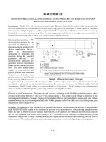
contact zone.
Fig.
18.70
Idealized schematic illustration
of the
stress concentrations produced
by the
abrasive pit-digging mechanism.
Fig.
18.71
Idealized schematic illustration
of the
stress concentrations produced
by the
asperity-contact microcrack initiation mechanism.
In
the
delamination theory
of
fretting
112
it is
hypothesized that
the
combination
of
normal
and
tangential tractive forces transmitted through
the
asperity-contact
sites
at the
fretting interface produce
a
complex multiaxial state
of
stress, accompanied
by a
cycling deformation
field,
which produces
subsurface
peak shearing stress
and
subsurface crack nucleation sites. With
further
cycling,
the
cracks
propagate
approximately parallel
to the
surface,
as
in
the
case
of the
surface fatigue phenomenon,
finally
propagating
to the
surface
to
produce
a
thin wear sheet, which
"delaminates"
to
become
a
particle
of
debris.
Supporting
evidence
has
been generated
to
indicate that under various circumstances each
of the
four
mechanisms
is
active
and
significant
in
producing fretting damage.
The
influence
of the
state
of
stress
in the
member during
the
fretting
is
shown
for
several
different
cases
in
Fig.
18.73,
including static
tensile
and
compressive
mean
stresses
during fretting.
An
inter-
esting observation
in
Fig. 18.73
is
that fretting under conditions
of
compressive mean stress,
either
static
or
cyclic, produces
a
drastic reduction
in
fatigue properties. This,
at first,
does
not
seem
to be
in
keeping with
the
concept that compressive stresses
are
beneficial
in
fatigue loading. However,
it
was
deduced
121
that
the
compressive stresses during
fretting
shown
in
Fig. 18.73 actually resulted
in
local residual tensile stresses
in the
fretted region. Likewise,
the
tensile stresses during fretting shown
in
Fig. 18.73 actually resulted
in
local residual compressive stresses
in the
fretted
region.
The
con-
clusion,
therefore,
is
that local compressive stresses
are
beneficial
in
minimizing
fretting
fatigue
damage.
Further evidence
of the
beneficial
effects
of
compressive residual stresses
in
minimizing fretting
fatigue
damage
is
illustrated
in
Fig. 18.74, where
the
results
of a
series
of
Prot (fatigue limit) tests
are
reported
for
steel
and titanium
specimens subjected
to
various combinations
of
shot peening
and
fretting
or
cold rolling
and
fretting.
It is
clear
from
these results that
the
residual compressive stresses
produced
by
shot peening
and
cold rolling
are
effective
in
minimizing
the
fretting
damage.
The
reduction
in
scatter
of the
fretted
fatigue properties
for
titanium
is
especially important
to a
designer
because design stress
is
closely related
to the
lower limit
of the
scatter band.
Recent
efforts
to
apply
the
tools
of
fracture mechanics
to the
problem
of
life
prediction under
fretting
fatigue conditions have produced encouraging preliminary results that
may
ultimately provide
designers with a viable quantitative
approach.
122
These
studies emphasize that the principal
effect
of
fretting
in the
fatigue failure process
is to
accelerate crack initiation
and the
early stages
of
crack
growth,
and
they suggest that when cracks have reached
a
sufficient
length,
the
fretting
no
longer
Fig.
18.72
Idealized schematic illustration
of the
tangential stress components
and
micro-
cracks produced
by the
friction-generated microcrack
initiation
mechanism.
has a
significant
influence
on
crack propagation.
At
this point
the
fracture mechanics description
of
crack propagation
described
in
Section
18.5.8
becomes
valid.
In
the final
analysis,
it is
necessary
to
evaluate
the
seriousness
of
fretting fatigue damage
in any
specific
design
by
running simulated service tests
on
specimens
or
components. Within
the
current
state-of-the-art
knowledge
in the
area
of
fretting fatigue, there
is no
other
safe
course
of
action open
to
the
designer.
Fretting wear
is a
change
in
dimensions through wear directly attributable
to the
fretting
process
between
two
mating surfaces.
It is
thought that
the
abrasive pit-digging mechanism,
the
asperity-
contact
microcrack initiation mechanism,
and the
wear-sheet
delamination
mechanism
may all be
important
in
most
fretting
wear failures.
As in the
case
of
fretting fatigue, there
has
been
no
good
model developed
to
describe
the
fretting wear phenomenon
in a way
useful
for
design.
An
expression
for
weight loss
due to
fretting
has
been
proposed
102
as
W
10-1
=
(V-
1
'
2
-
*i«
i
+
k
2
SLC
(18.86)
r
Fig.
18.73
Residual fatigue properties subsequent
to
fretting under various states
of
stress.
where
W
total
=
total specimen weight loss
L
=
normal contact load
C =
number
of
fretting
cycles
F
=
frequency
of
fretting
S
=
peak-to-peak slip between
fretting
surfaces
&
0
,
Jt
1
,
k
2
=
constants
to be
empirically determined
This equation
has
been shown
to
give relatively good agreement with experimental data over
a
range
of
fretting
conditions using mild steel
specimens.
102
However, weight loss
is not of
direct
use
to a
designer. Wear depth
is of
more interest. Prediction
of
wear depth
in an
actual design application
must
in
general
be
based
on
simulated service testing.
Some investigators have suggested that estimates
of
fretting wear depth
may be
based
on the
classical adhesive
or
abrasive wear equations,
in
which wear depth
is
proportional
to
load
and
total
distance slid, where
the
total distance slid
is
calculated
by
multiplying relative motion
per
cycle times
number
of
cycles. Although there
are
some supporting data
for
such
a
procedure,
123
more investigation
is
required before
it
could
be
recommended
as an
acceptable
approach
for
general
application.
If
fretting wear
at a
support interface, such
as
between tubes
and
support plates
of a
steam
generator
or
heat exchanger
or
between
fuel
pins
and
support grids
of a
reactor
core,
produces
loss
of
fit at a
support
site, impact
fretting
may
occur. Impact
fretting
is
fretting
action induced
by the
small
lateral relative displacements between
two
surfaces when they impact together, where
the
small
displacements
are
caused
by
Poisson strains
or
small tangential
"glancing"
velocity components.
Impact
fretting
has
only recently been addressed
in the
literature,
124
but it
should
be
noted that under
certain
circumstances impact
fretting
may be a
potential failure mode
of
great importance.
Fretting
corrosion
may be
defined
as any
corrosive surface involvement resulting
as a
direct result
of
fretting
action.
The
consequences
of
fretting
corrosion
are
generally much less severe than
for
either
fretting
wear
or
fretting
fatigue. Note that
the
term fretting corrosion
is not
being used here
Test Condition Used
Nonf
retted,
polished,
SAE
4340
steel
Nonf
retted,
polished,
Ti-
140-
A
titanium
Nonf
retted,
mildly
shot-peened,
Ti-
140-
A
titanium
Nonfretted,
severely
shot-peened,
Ti-140-A
titanium
Nonfretted,
mildly
cold-rolled,
Ti-140-A
titanium
Nonfretted,
severely cold-rolled,
Ti-140-A
titanium
Mildly
fretted,
polished,
SAE
4340
steel
Medium
fretted,
polished,
SAE
4340
steel
Severely
fretted,
polished,
SAE
4340
steel
Mildly
fretted,
polished,
Ti-140-A
titanium
Medium
fretted,
polished,
Ti-140-A
titanium
Severely
fretted,
polished,
Ti-140-A
titanium
Mildly
fretted,
mildly shot-peened,
Ti-140-A
titanium
Medium
fretted,
mildly
shot-peened,
Ti-140-A
titanium
Severely
fretted,
mildly
shot-peened,
Ti-140-A
titanium
Mildly
fretted,
severely shot-peened,
Ti-140-A
titanium
Medium
fretted,
severely shot-peened,
Ti-140-A
titanium
Severely
fretted,
severely shot-peened,
Ti-140-A
titanium
Mildly
fretted,
mildly cold-rolled,
Ti-140-A
titanium
Medium
fretted,
mildly
cold-rolled,
Ti-140-A
titanium
Severely
fretted,
mildly
cold-rolled,
Ti-140-A
titanium
Mildly
fretted,
severely cold-rolled,
Ti-140-A
titanium
Medium
fretted,
severely cold-rolled,
Ti-140-A
titanium
Severely
fretted,
severely cold-rolled.
Ti-140-A
titanium
Code
Designation
NF-P-S
NF-P-T
NF-MSP-T
NF-SSP-T
NF-MCR-T
NF-SCR-T
MF-P-S
MeF-P-S
SF-P-S
MF-P-T
MeF-P-T
SF-P-T
MF-MSP-T
MeF-MSP-T
SF-MSP-T
MF-SSP-T
MeF-SSP-T
SF-SSP-T
MF-MCR-T
MeF-MCR-T
SF-MCR-T
MF-SCR-T
MeF-SCR-T
SF-SCR-T
Sample
Size
15
15
15
15
15
15
15
15
15
15
15
15
15
15
15
15
15
15
15
15
15
15
15
15
Mean
Prot
Failure
Stress,
psi
78,200
77,800
83,100
85,700
85,430
95,400
77,280
71,850
67,700
81,050
58,140
38,660
84,520
84,930
84,870
83,600
83,240
83,110
82,050
76,930
67,960
93,690
91,950
93,150
Unbiased
Standard
Deviation,
psi
5,456
2,454
1,637
2,398
1,924
2,120
4,155
5,492
6,532
3,733
15,715
19,342
5,239
2,446
2,647
1,474
1,332
1,280
4,313
8,305
5,682
1,858
2,098
1,365
Fig.
18.74
Fatigue
properties
of
fretted
steel
and
titanium
specimens
with
various
degrees
of
shot
peening
and
cold
rolling.
(See
Ref. 106.)
as
a
synonym
for
fretting,
as in
much
of the
early literature
on
this topic. Perhaps
the
most important
single
parameter
in
minimizing
fretting
corrosion
is
proper selection
of the
material pair
for the
application. Table
18.5
lists
a
variety
of
material pairs grouped according
to
their resistance
to
fretting
corrosion.
125
Cross comparisons
from
one
investigator's results
to
another's must
be
made with care
because testing conditions varied widely.
The
minimization
or
prevention
of
fretting
damage must
be
carefully
considered
as a
separate problem
in
each individual design application because
a
palli-
ative
in one
application
may
significantly
accelerate
fretting
damage
in a
different
application.
For
example,
in a
joint that
is
designed
to
have
no
relative motion,
it is
sometimes
possible
to
reduce
or
prevent
fretting
by
increasing
the
normal pressure until
all
relative motion
is
arrested.
However,
if
the
increase
in
normal pressure does
not
completely arrest
the
relative motion,
the
result
may be
significantly
increasing
fretting
damage instead
of
preventing
it.
Nevertheless, there
are
several basic principles that
are
generally
effective
in
minimizing
or
pre-
venting
fretting.
These include:
1.
Complete separation
of the
contacting surfaces.
2.
Elimination
of all
relative motion between
the
contacting surfaces.
3. If
relative motion cannot
be
eliminated,
it is
sometimes
effective
to
superpose
a
large uni-
directional
relative motion that allows
effective
lubrication.
For
example,
the
practice
of
driv-
ing
the
inner
or
outer race
of an
oscillatory pivot bearing
may be
effective
in
eliminating
fretting.
4.
Providing
compressive
residual stresses
at the
fretting
surface;
this
may be
accomplished
by
shot
peening, cold rolling,
or
interference
fit
techniques.
5.
Judicious selection
of
material pairs.
6. Use of
interposed low-shear-modulus shim material
or
plating, such
as
lead, rubber,
or
silver.
7. Use of
surface
treatments
or
coatings
as
solid lubricants.
8. Use of
surface
grooving
or
roughening
to
provide debris escape routes
and
differential
strain
matching
through elastic action.
Of
all
these techniques, only
the first two are
completely
effective
in
preventing
fretting.
The re-
maining
concepts, however,
may
often
be
used
to
minimize
fretting
damage
and
yield
an
acceptable
design.
18.8.2
Wear Phenomena
The
complexity
of the
wear process
may be
better appreciated
by
recognizing that many variables
are
involved, including
the
hardness, toughness, ductility, modulus
of
elasticity,
yield
strength, fatigue
properties,
and
structure
and
composition
of the
mating surfaces,
as
well
as
geometry, contact pres-
sure,
temperature, state
of
stress, stress distribution,
coefficient
of
friction, sliding distance, relative
velocity,
surface
finish,
lubricants, contaminants,
and
ambient atmosphere
at the
wearing interface.
Clearance versus contact-time history
of the
wearing surfaces
may
also
be an
important factor
in
some cases. Although
the
wear processes
are
complex, progress
has
been made
in
recent years toward
development
of
quantitative empirical relationships
for the
various subcategories
of
wear under spec-
ified
operating conditions. Adhesive wear
is
often
characterized
as the
most basic
or
fundamental
subcategory
of
wear since
it
occurs
to
some degree whenever
two
solid surfaces
are in
rubbing
contact
and
remains active even when
all
other modes
of
wear have been eliminated.
The
phenomenon
of
adhesive wear
may be
best understood
by
recalling that
all
real surfaces,
no
matter
how
carefully
prepared
and
polished, exhibit
a
general waviness upon which
is
superposed
a
distribution
of
local
protuberances
or
asperities.
As two
surfaces
are
brought into contact, therefore, only
a
relatively
few
asperities actually touch,
and the
real
area
of
contact
is
only
a
small
fraction
of the
apparent
contact
area.
(See Chap.
1 of
Ref.
126 and
Chap.
2 of
Ref. 127.) Thus, even under very small applied loads
the
local pressures
at the
contact sites become high enough
to
exceed
the
yield strength
of one or
both
surfaces,
and
local plastic
flow
ensues.
If the
contacting surfaces
are
clean
and
uncorroded,
the
very
intimate contact generated
by
this local plastic
flow
brings
the
atoms
of the two
contacting
surfaces
close enough together
to
call
into play strong adhesive forces. This process
is
sometimes
called
cold
welding.
Then
if the
surfaces
are
subjected
to
relative sliding motion,
the
cold-welded
junctions
must
be
broken. Whether they break
at the
original interface
or
elsewhere within
the
asperity
depends
on
surface conditions, temperature distribution, strain-hardening characteristics, local
ge-
ometry,
and
stress distribution.
If the
junction
is
broken away
from
the
original interface,
a
particle
of
one
surface
is
transferred
to the
other surface, marking
one
event
in the
adhesive wear process.
Later sliding interactions
may
dislodge
the
transferred particles
as
loose
wear
particles,
or
they
may
remain
attached.
If
this adhesive wear
process
becomes severe
and
large-scale
metal transfer takes
place,
the
phenomenon
is
called galling.
If the
galling becomes
so
severe that
two
surfaces adhere
over
a
large region
so
that
the
actuating forces
can no
longer produce relative motion between them,
the
phenomenon
is
called seizure.
If
properly controlled, however,
the
adhesive wear rate
may be
Sakmann
and
Rightmire
Gray
and
Jenny
McDowell
Sakmann
and
Rightmire
Gray
and
Jenny
McDowell
Sakmann
and
Rightmire
Gray
and
Jenny
Lead
on
Steel
Silver plate
on
Steel
Silver plate
on
Silver plate
'Parco-lubrized'
steel
on
Steel
Grit blasted steel plus lead plate
on
Steel
(very
good)
1/16
in.
nylon insert
on
Steel (very good)
Zinc
and
iron phosphated
on
Steel (good with thick coat)
(Bonderizing) steel
Laminated plastic
on
Gold plate
Hard tool steel
on
Tool steel
Cold-rolled
steel
on
Cold-rolled steel
Cast iron
on
Cast iron with phosphate
coating
Cast iron
on
Cast iron with rubber cement
Cast
iron
on
Cast iron with tungsten
sulphide coating
Cast iron
on
Cast iron with rubber insert
Cast iron
on
Cast iron with Molykote
lubricant
Cast iron
on
Stainless steel with Molykote
lubricant
Material
Pairs
Having
Intermediate
Fretting
Corrosion
Resistance
Cadmium
on
Steel
Zinc
on
Steel
Copper
alloy
on
Steel
Zinc
on
Aluminum
Copper plate
on
Aluminum
Nickel plate
on
Aluminum
Silver plate
on
Aluminum
Iron plate
on
Aluminum
Sulphide coated bronze
on
Steel
Cast bronze
on
"Parco-lubrized"
steel
Magnesium
on
"Parco-lubrized"
steel
Grit-blasted steel
on
Steel
Cast iron
on
Cast iron (rough
or
smooth
surface)
Copper
on
Cast iron
Brass
on
Cast iron
Zinc
on
Cast iron
Cast iron
on
Silver plate
Cast
iron
on
Copper plate
Magnesium
on
Copper plate
Zirconium
on
Zirconium
Steel
on
Steel
Nickel
on
Steel
Aluminum
on
Steel
Al-Si alloy
on
Steel
Antimony
plate
on
Steel
Tin
on
Steel
Aluminium
on
Aluminum
Zinc plate
on
Aluminum
Grit blast plus silver plate
on
Steel*
Steel
on
Steel
Grit blast plus copper plate
on
Steel
Grit blast plus
tin
plate
on
Steel
Grit blast
and
aluminium
foil
on
Steel
Be-Cu insert
on
Steel
Magnesium
on
Steel
Nitrided
steel
on
Chromium plated
steelt
Table
18.5
Fretting
Corrosion
Resistance
of
Various
Material
Pairs
125
Material
Pairs
Having Good Fretting Corrosion Resistance
Table
18.5
(Continued)
Material
Pairs Having Poor Fretting Corrosion
Resistance
McDowell Aluminium
on
Cast iron
Aluminum
on
Stainless
steel
Magnesium
on
Cast iron
Cast
iron
on
Chromium plate
Laminated plastic
on
Cast iron
Bakelite
on
Cast iron
Hard tool steel
on
Stainless steel
Chromium plate
on
Chromium plate
Cast iron
on Tin
plate
Gold plate
on
Gold plate
*Possibly
effective
with light loads
and
thick
(0.005
inch) silver plate.
tSome
improvement
by
heating chromium plated steel
to
538
0
C
for 1
hour.
low
and
self-limiting,
often
being exploited
in the
"wearing-in"
process
to
improve mating surfaces
such
as
bearings
or
cylinders
so
that
full
film
lubrication
may be
effectively
used.
One
quantitative estimate
of the
amount
of
adhesive wear
is
given
as
follows (see Ref.
113
and
Chaps.
2 and 6 of
Ref. 128):
.
V.*
/
k
\(W\
^-"teJtaJ
1
*
(107)
or
fiU =
k*j>
m
L.
(18.88)
where
J
adh
is the
average wear depth,
A
a
is the
apparent contact area,
L
5
is the
total sliding distance,
V
adh
is the
wear volume,
W is the
applied load,
p
m
=
W/A
a
is the
mean nominal contact pressure
between
bearing surfaces,
and
£
adh
=
k/9cr
yp
is a
wear
coefficient
that depends
on the
probability
of
formation
of a
transferred
fragment
and the
yield strength
(or
hardness)
of the
softer
material. Typical
values
of the
wear constant
k for
several material
paris
are
shown
in
Table 18.6,
and the
influence
of
lubrication
on the
wear constant
k is
indicated
in
Table 18.7.
Noting
from
(18.88) that
*adh
=
-=7-
(18.89)
Pm
L
s
it may be
observed that
if the
ratio
d
adh
/p
m
L
s
is
experimentally
found
to be
constant,
(18.88)
should
be
valid. Experimental evidence
has
been accumulated (see
pp.
124-125
of
Ref.
113)
to
confirm
that
for
a
given material pair this ratio
is
constant
up to
mean nominal contact pressures approximately
equal
to the
uniaxial yield strength. Above this level
the
adhesive wear
coefficient
increases rapidly,
with attendant severe galling
and
seizure.
Table
18.6
Archard Adhesive Wear Constant
k for
Various
Unlubricated Material Pairs
in
Sliding
Contact
8
Material Pair Wear Constant
k
Zinc
on
zinc
160 X
10~
3
Low-carbon steel
on
low-carbon steel
45 x
10~
3
Copper
on
copper
32 X
10~
3
Stainless steel
on
stainless steel
21 X
10~
3
Copper
(on
low-carbon steel)
1.5 X
10~
3
Low-carbon steel
(on
copper)
0.5 x
10~
3
Bakelite
on
bakelite
0.02
x
10~
3
"From
Chap.
6 of
Ref. 128, with permission
of
John Wiley
&
Sons.
Table
18.7
Order
of
Magnitude
Values
for
Adhesive
Wear
Constant
k
Under
Various
Conditions
of
Lubrication
3
Metal
(on
Metal)Nonmetal
Lubrication
Condition
Like
Unlike
(on
Metal)
Unlubricated
5 X
10~
3
2 X
1(T
4
5 X
10~
6
Poorly lubricated
2 X
10~
4
2 X
1(T
4
5 X
1(T
6
Average
lubrication
2 X
10~
5
2 X
10~
5
5 X
ICT
6
Excellent lubrication
2 X
10~
6
to
1Q~
7
2 X
1(T
6
to
IQ"
7
2 X
10~
6
"From
Chap.
6 of
Ref. 128, with permission
of
John Wiley
&
Sons.
In
the
selection
of
metal combinations
to
provide resistance
to
adhesive wear,
it has
been
found
that
the
sliding pair should
be
composed
of
mutually insoluble metals
and
that
at
least
one of the
metals should
be
from
the B
subgroup
of the
periodic table. (See
p. 31 of
Ref. 129.)
The
reasons
for
these observations
are
that
the
number
of
cold-weld junctions formed
is a
function
of the
mutual
solubility,
and the
strength
of the
junction bonds
is a
function
of the
bonding characteristics
of the
metals involved.
The
metals
in the B
subgroup
of the
periodic
table
are
characterized
by
weak, brittle
covalent bonds. These criteria have been
verified
experimentally,
as
shown
in
Table
18.8,
where
114
of
123
pairs tested substantiated
the
criteria.
In
the
case
of
abrasive wear,
the
wear particles
are
removed
from
the
surface
by the
plowing
and
gouging
action
of the
asperities
of a
harder mating surface
or by
hard particles trapped between
the
rubbing surfaces. This type
of
wear
is
manifested
by a
system
of
surface grooves
and
scratches,
often
called scoring.
The
abrasive wear condition
in
which
the
hard asperities
of one
surface
wear away
the
mating
surface
is
commonly called
two-body
wear,
and the
condition
in
which hard abrasive
particles between
the two
surfaces cause
the
wear
is
called
three-body
wear.
An
average abrasive wear depth
d
abr
may
then
be
estimated
as
V
abr
(tan
0)
m
fw\
^
-
f
=
!^r=
y
L
>
(18
'
90)
or
4,br
=
k*,p
m
L.
(18.91)
where
W is
total applied load, (tan
0)
m
is a
weighted mean value
for all
asperities,
L
s
is a
total
distance
of
sliding,
a
yp
is the
uniaxial yield point strength
for the
softer
material,
V
abr
is
abrasive
wear volume,
p
m
=
W/A
a
is
mean nominal contact pressure between bearing surfaces,
and
&
abr
=
(tan
6)
m
/37ro~
yp
is an
abrasive wear
coefficient
that depends
on the
roughness characteristics
of the
surface
and the
yield strength
(or
hardness)
of the
softer
material.
Comparing (18.90)
for
abrasive wear volume with (18.87)
for
adhesive wear volume,
we
note
that
they
are
formally
the
same except
the
constant
k/3
in the
adhesive wear equation
is
replaced
by
(tan
Q)
m
lir
in the
abrasive wear equation. Typical values
of the
wear constant 3(tan
6)
m
l
TT
for
several
materials
are
shown
in
Table
18.9.
As
indicated
in
Table
18.9,
experimental evidence shows that
fc
abr
for
three-body wear
is
typically about
an
order
of
magnitude smaller
than
for the
two-body case,
probably because
the
trapped particles tend
to
roll
much
of the
time
and cut
only
a
small part
of the
time.
In
selecting materials
for
abrasive wear resistance,
it has
been established that both hardness
and
modulus
of
elasticity
are key
properties. Increasing wear resistance
is
associated with higher hardness
and
lower modulus
of
elasticity since both
the
amount
of
elastic deformation
and the
amount
of
elastic energy that
can be
stored
at the
surface
are
increased
by
higher hardness
and
lower modulus
of
elasticity.
Table
18.10
tabulates several materials
in
order
of
descending values
of
(hardness)/(modulus
of
elasticity). Well-controlled experimental data
are not yet
available,
but
general experience would
provide
an
ordering
of
materials
for
decreasing wear resistance compatible with
the
array
of
Table
18.10.
When
the
conditions
for
adhesive
or
abrasive wear exist together with conditions that lead
to
corrosion,
the two
processes
persist together
and
often
interact synergistically.
If the
corrosion product
is
hard
and
abrasive, dislodged corrosion particles trapped between contacting surfaces will
accelerate
the
abrasive wear
process.
In
turn,
the
wear
process
may
remove
the
"protective"
surface layer
of
corrosion product
to
bare
new
metal
to the
corrosive atmosphere, thereby accelerating
the
corrosion
process. Thus,
the
corrosion wear process
may be
self-accelerating
and may
lead
to
high rates
of
wear.
Description
of
Metal
Pair
Soluble pairs with poor
adhesive wear resistance
Soluble pairs with
fair
or
good adhesive wear
resistance.
(F) =
Fair
Insoluble
pairs, neither
from
the B
subgroup,
with
poor adhesive wear
resistance
Insoluble pairs,
one
from
the B
subgroup, with
fair
or
good adhesive
wear
resistance.
(F)
=
Fair
Insoluble pairs,
one
from
the B
subgroup, with
poor adhesive wear
resistance
"See
pp.
34-35
of
Ref. 129.
Al
Disk
Be
Mg
Al
Si
Ca
Ti
Cr
Fe
Co
Ni
Cu
Zr
Nb
Mo
Rh
Ag
Sn
Ce
Ta
W
Pt
Au
Th
U
Zn(F)
Cd
In
Te(F)
Tl
Pb(F)
Bi(F)
C
Se
Steel
Disk
Be
Al
Si
Ti
Cr
Mn
Fe
Co
Ni
Zn
Zr
Nb
Mo
Rh
Pd
Ce
Ta
W
Ir
Pt
Au
Th
U
Cu(F)
Li
Mg
Ca
Ba
C(F)
Se(F)
Ag
Cd
In
Sn(F)
Sb(F)
Te(F)
Tl
Pb
Bi
Cu
Disk
Be
Mg
Al
Si
Ca
Ti
Co
Ni
Cu
Zn
Zr
Nb
Mo
Rh
Ag
Cd
In
Sn
Ce
Ta
W
Pt
Au
Th
U
Sb(F)
Cr(F)
Ge(F)
Se(F)
Sb
Te(F)
Tl
Pb
Bi(F)
C
Ag
Disk
Be
Mg
Si
Zr
Cd
In
Au
Th
U
Ti(F)
Cr(F)
Fe(F)
Co(F)
Nb(F)
C
Ni
Mo
Remarks
These pairs substantiate
the
criteria
of
solubility
and
B
subgroup metals
These pairs
do not
substantiate
the
stated
criteria
These pairs substantiate
the
stated
criteria
These pairs substantiate
the
stated
criteria
These pairs
do not
substantiate
the
stated
criteria
Table
18.8
Adhesive Wear Behavior
of
Various
Pairs
3
Material Combination
Table
18.9
Abrasive Wear Constant 3(tan
6)
m
/iT
for
Various
Materials
in
Sliding Contact
as
Reported
by
Different
Investigators
3
Materials
Wear
Type
Particle Size,
^t
3(tan
Q]
m
I
TT
Many
Two-body
— 180 X
10~
3
Many
Two-body
110 150 X
10~
3
Many
Two-body
40-150
120 X
10"
3
Steel
Two-body
260 80 X
10~
3
Many
Two-body
80 24 X
10~
3
Brass Two-body
70 16 X
10~
3
Steel
Three-body
150 6 x
10~
3
Steel Three-body
80 4.5 X
15~
3
Many
Three-body
40 2 X
10"
3
*See
p. 169 of
Ref. 128. Reprinted with permission
from
John Wiley
&
Sons.
On
the
other hand, some corrosion products,
for
example, metallic phosphates,
sulfides,
and
chlorides,
form
as
soft
lubricative
films
that actually improve
the
wear rate markedly, especially
if
adhesive wear
is the
dominant phenomenon.
Three
major
wear control methods have been
defined,
as
follows (see
p. 36 of
Ref. 129): principle
of
protective
layers,
including protection
by
lubricant, surface
film,
paint, plating, phosphate, chem-
ical,
flame-sprayed, or
other types
of
interfacial layers: principle
of
conversion,
in
which wear
is
converted
from
destructive
to
permissible levels through better choice
of
metal pairs, hardness,
surface
finish, or
contact pressure:
and
principle
of
diversion,
in
which
the
wear
is
diverted
to an
economical
replaceable
wear element that
is
periodically discarded
and
replaced
as
"wear
out" occurs. When
two
surfaces operate
in
rolling contact,
the
wear phenomenon
is
quite
different
from
the
wear
of
sliding surfaces just described, although
the
"delamination"
theory
130
is
very similar
to the
mecha-
nism
of
wear between rolling surfaces
in
contact
as
described
here.
Rolling
surfaces
in
contact result
Table
18.10
Values
of
(Hardness/Modulus
of
Elasticity)
for
Various
Materials
113
1
BHNV(EX
10-
6
)
Material Condition
(in
mixed units)
Alundum
(Al
2
O
3
) Bonded
143
Chrome plate Bright
83
Gray
iron Hard
33
Tungsten
carbide
9% Co 22
Steel Hard
21
Titanium Hard
17
Aluminum
alloy Hard
11
Gray iron
As
cast
10
Structural
steel
Soft
5
Malleable iron
Soft
5
Wrought
iron
Soft
3.5
Chromium
metal
As
cast
3.5
Copper
Soft
2.5
Silver Pure
2.3
Aluminum
Pure
2.0
Lead Pure
2.0
Tin
Pure
0.7
!Reprinted
from
copyrighted work with permission; cour-
tesy
of
Elsevier Publishing Company.
*Brinell
hardness number.
in
Hertz contact stresses that produce maximum values
of
shear stress slightly below
the
surface.
(See,
for
example,
p. 389 of
Ref.
131.)
As the
rolling contact zone moves past
a
given location
on
the
surface,
the
subsurface peak shear stress cycles
from
zero
to a
maximum value
and
back
to
zero,
thus
producing
a
cyclic stress
field.
Such conditions
may
lead
to
fatigue failure
by the
initiation
of
a
subsurface crack that propagates under repeated cyclic loading
and
that
may
ultimately propagate
to
the
surface
to
spall
out a
macroscopic surface particle
to
form
a
wear pit. This action,
called
surface
fatigue
wear,
is a
common failure mode
in
antifriction bearings, gears,
and
cams,
and all
machine parts
that
involve rolling surfaces
in
contact. Deformation wear arises
as a
result
of
repeated
plastic deformations
at the
wearing
surfaces;
this wear
may
induce
a
matrix
of
cracks that grow
and
coalesce
to
form
wear particles
or may
produce cumulative permanent plastic deformations that
finally
grow
into
an
unacceptable
surface
indentation
or
wear scar. Deformation wear
is
generally caused
by
conditions that lead
to
impact loading between
the two
wearing surfaces. Although some progress
has
been made
in
deformation wear analysis,
the
techniques
are
highly specialized. Fretting wear,
which
has
received renewed attention
in the
recent literature (see
p. 55 of
Ref.
132 and p. 75 of
Ref.
128),
has
already been discussed. Impact wear
is a
term reserved
for
impact-induced repeated elastic
deformations
at the
wearing surfaces that produce
a
matrix
of
cracks that grow
in
accordance with
surface
fatigue phenomena. Under some circumstances impact wear
may be
generated
by
purely
normal impacts,
and
under other circumstances
the
impact
may
contain elements
of
rolling
and/or
sliding
as
well.
The
severity
of the
impact
is
generally measured
or
expressed
in
terms
of the
kinetic
energy
of the
striking mass.
The
geometry
of the
impacting surfaces
and the
material properties
of
the two
contacting surfaces play
a
major
role
in the
determination
of
severity
of
impact wear damage.
The
objective
of a
designer
faced
with impact wear
as a
potential failure mode
is to
predict
the
size
of
the
wear scar,
or its
depth,
as a
function
of the
number
of
repetitive load cycles.
An
empirical approach
to the
prediction
of
sliding wear
has
been
developed,
133
and the
pertinent
empirical constants have
been
evaluated
for a
wide variety
of
materials
and
lubricant combinations
for
various operating conditions. This empirical development permits
the
designer
to
specify
a
design
configuration
to
ensure
"zero
wear"
during
the
specified
design lifetime. Zero wear
is
defined
to be
wear
of
such small magnitude that
the
surface
finish is not
significantly
altered
by the
wear process.
That
is, the
wear depth
for
zero wear
is of the
order
of
one-half
the
peak-to-peak surface
finish
dimension.
If
a
pass
is
defined
to be a
distance
of
sliding
W
equal
to the
dimension
of the
contact area
in
the
direction
of
sliding,
TV
is the
number
of
passes,
r
max
is the
maximum shearing stress
in the
vicinity
of
the
surface,
r
yp
is the
shear yield point
of the
specified material,
and
y
r
is a
constant
for the
particular combination
of
materials
and
lubricant, then
the
empirical model asserts that there will
be
"zero
wear"
for N
passes
if
[2 X
1O
3
T
79
r
max
^
[—jj—\
y
r
r
yp
(18.92)
or,
to
interpret
it
differently,
the
number
of
passes that
can be
accommodated without exceeding
the
zero wear level
is
given
by
N
=
2 X
10
3
—
(18.93)
L
Tmax
J
It may be
noted that
the
constant
y
r
is
referred
to
2000 passes
and
must
be
experimentally determined.
For
quasihydrodynamic lubrication,
y
r
ranges between 0.54
and 1. For dry or
boundary lubrication,
y
r
is
0.54
for
materials with
low
susceptibility
to
adhesive wear
and
0.20
for
materials with high
susceptibility
to
adhesive wear.
Calculation
of the
maximum shear stress
r
max
in the
vicinity
of the
contacting surface must include
both
the
normal
force
and the
friction
force. Thus,
for
conforming geometries, such
as a flat
surface
on
a flat
surface
or a
shaft
in a
journal bearing,
a
critical point
at the
contacting interface
may be
analyzed
by the
maximum shear stress theory
to
determine
r
max
.
The
number
of
passes will usually require expression
as a
function
of the
number
of
cycles,
strokes,
oscillations,
or
hours
of
operation
in the
design lifetime.
Utilizing these
definitions
and a
proper stress analysis
at the
wear interface allows
one to
design
for
"zero
wear"
through
use of
Eqs. (18.92)
or
(18.93).
18.9 CORROSION
AND
STRESS CORROSION
Corrosion
may be
defined
as the
undesired deterioration
of a
material through chemical
or
electro-
chemical interaction with
the
environment,
or
destruction
of
materials
by
means other than purely
mechanical action. Failure
by
corrosion occurs when
the
corrosive action renders
the
corroded device
incapable
of
performing
its
design
function.
Corrosion
often
interacts synergistically with another
failure
mode, such
as
wear
or
fatigue,
to
produce
the
even more serious combined failure modes,
such
as
corrosion wear
or
corrosion fatigue. Failure
by
corrosion
and
protection against failure
by
corrosion
has
been estimated
to
cost
in
excess
of 8
billion dollars annually
in the
United States alone.
(See
p. 1 of
Ref. 134.)
The
complexity
of the
corrosion process
may be
better appreciated
by
recognizing that
many
variables
are
involved, including environmental, electrochemical,
and
metallurgical aspects.
For ex-
ample, anodic reactions
and
rate
of
oxidation; cathodic reactions
and
rate
of
reduction; corrosion
inhibition, polarization,
or
retardation; passivity phenomena;
effect
of
oxidizers;
effect
of
velocity;
temperature; corrosive concentration; galvanic coupling;
and
metallurgical structure
all
influence
the
type
and
rate
of the
corrosion process.
Corrosion
processes
have been categorized
in
many
different
ways.
One
convenient
classification
divides corrosion phenomena into
the
following types (see
p. 28 of
Ref.
134 and p. 85 of
Ref. 135):
direct chemical attack, galvanic corrosion, crevice corrosion, pitting corrosion, intergranular corrosion,
selective leaching, erosion corrosion, cavitation corrosion, hydrogen damage, biological corrosion,
and
stress corrosion cracking. Depending
on the
types
of
environment, loading,
and
mechanical
function
of the
machine parts involved,
any of the
types
of
corrosion
may
combine their
influence
with
other failure modes
to
produce premature failures.
Of
particular concern
are
interactions that
lead
to
failure
by
corrosion wear, corrosion
fatigue,
fretting
fatigue,
and
corrosion-induced brittle
fracture.
18.9.1
Types
of
Corrosion
Direct chemical attack
is
probably
the
most common type
of
corrosion. Under this type
of
corrosive
attack
the
surface
of the
machine part exposed
to the
corrosive media
is
attacked more
or
less
uniformly
over
its
entire surface, resulting
in a
progressive deterioration
and
dimensional reduction
of
sound load-carrying
net
cross section.
The
rate
of
corrosion
due to
direct attack
can
usually
be
estimated
from
relatively simple laboratory tests
in
which small specimens
of the
selected material
are
exposed
to a
well-simulated actual environment, with
frequent
weight change
and
dimensional
measurements
carefully
taken.
The
corrosion rate
is
usually expressed
in
mils
per
year (mpy)
and
may
be
calculated
as
(see
p. 133 of
Ref. 134)
*
=
^
(18.94)
yAt
where
R is
rate
of
corrosion penetration
in
mils
(1 mil =
0.001 in.)
per
year (mpy),
W is
weight loss
in
milligrams,
A is
exposed area
of the
specimen
in
square inches,
y is
density
of the
specimen
in
grams
per
cubic centimeter,
and t is
exposure time
in
hours.
Use of
this corrosion rate expression
in
predicting corrosion penetration
in
actual service
is
usually
successful
if the
environment
has
been
properly simulated
in the
laboratory. Corrosion rate data
for
many
different
combinations
of
materials
and
environments
are
available
in the
literature.
136
"
138
Figure 18.75 illustrates
one
presentation
of
such data.
Direct chemical attack
may be
reduced
in
severity
or
prevented
by any one or a
combination
of
several means, including selecting proper materials
to
suit
the
environment; using plating,
flame
spraying,
cladding,
hot
dipping, vapor deposition, conversion coatings,
and
organic coatings
or
paint
to
protect
the
base material; changing
the
environment
by
using lower temperature
or
lower velocity,
removing oxygen, changing corrosive concentration,
or
adding corrosion inhibitors; using cathodic
protection
in
which
electrons
are
supplied
to the
metal surface
to be
protected either
by
galvanic
coupling
to a
sacrificial anode
or by an
external power supply;
or
adopting other suitable design
modifications.
Galvanic corrosion
is an
accelerated electrochemical corrosion that occurs when
two
dissimilar
metals
in
electrical
contact
are
made part
of a
circuit completed
by a
connecting pool
or film of
electrolyte
or
corrosive medium. Under these circumstances,
the
potential
difference
between
the
dissimilar metals produces
a
current
flow
through
the
connecting electrolyte, which leads
to
corrosion,
concentrated primarily
in the
more anodic
or
less noble metal
of the
pair. This type
of
action
is
completely analogous
to a
simple battery
cell.
Current must
flow to
produce galvanic corrosion, and,
in
general, more current
flow
means more serious corrosion.
The
relative tendencies
of
various metals
to
form
galvanic
cells,
and the
probable direction
of the
galvanic action,
are
illustrated
for
several
commercial metals
and
alloys
in
seawater
in
Table
18.11.
(See
p. 32 of
Ref.
134 or p. 86 of
Ref.
135.)
Ideally,
tests
in the
actual service environment should
be
conducted; but,
if
such data
are
una-
vailable,
the
data
of
Table
18.11
should give
a
good indication
of
possible galvanic action.
The
farther
apart
the two
dissimilar metals
are in the
galvanic series,
the
more serious
the
galvanic corrosion
problem
may be.
Material pairs within
any
bracketed group exhibit little
or no
galvanic action.
It
should
be
noted, however, that there
are
sometimes
exceptions
to
the
galvanic
series
of
Table
18.11,
so
wherever
possible
corrosion tests should
be
performed with actual materials
in the
actual service
environment.
The
accelerated galvanic corrosion
is
usually most severe near
the
junction between
the two
metals, decreasing
in
severity
at
locations
farther
from
the
junction.
The
ratio
of
cathodic area
to
anodic area exposed
to the
electrolyte
has a
significant
effect
on
corrosion rate.
It is
desirable
to
•
Corrosion rate
less
than
2
mpy
(mils/year)
o
Corrosion rate
less
than
20 mpy
D
Corrosion rate
from
20 to 50 mpy
x
Corrosion rate greater
than
50 mpy
Fig.
18.75
Nelson's method
for
summarizing corrosion rate data
for
lead
in
sulfuric
acid
environment
as a
function
of
concentration
and
temperature. (See Ref.
136;
reprinted with
permission
of
McGraw-Hill Book Company.)
have
a
small
ratio
of
cathode area
to
anode area.
For
this reason,
if
only
one of two
dissimilar metals
in
electrical contact
is to be
coated
for
corrosion protection,
the
more
noble
or
more corrosion-
resistant
metal should
be
coated. Although this
at first may
seem
the
wrong metal
to
coat,
the
area
effect,
which produces anodic corrosion rate
of
10
2
-10
3
times cathodic corrosion rates
for
equal
areas,
provides
the
logic
for
this assertion.
Galvanic corrosion
may be
reduced
in
severity
or
prevented
by one or a
combination
of
several
steps,
including
the
selection
of
material pairs
as
close together
as
possible
in the
galvanic series,
preferably
in the
same bracketed group; electrical insulation
of one
dissimilar metal
from
the
other
as
completely
as
possible; maintaining
as
small
a
ratio
of
cathode area
to
anode area
as
possible;
proper
use and
maintenance
of
coatings;
the use of
inhibitors
to
decrease
the
aggressiveness
of the
corroding
medium;
and the use of
cathodic protection
in
which
a
third metal element anodic
to
both
members
of the
operating pair
is
used
as a
sacrificial
anode that
may
require periodic replacement.
Crevice corrosion
is an
accelerated corrosion process highly localized within crevices, cracks,
and
other small-volume regions
of
stagnant solution
in
contact with
the
corroding metal.
For
example,
crevice corrosion
may be
expected
in
gasketed joints; clamped interfaces;
lap
joints; rolled joints;
under
bolt
and rivet
heads;
and
under foreign deposits
of
dirt, sand, scale,
or
corrosion product. Until
recently,
crevice corrosion
was
thought
to
result
from
differences
in
either oxygen concentration
or
metal
ion
concentration
in the
crevice compared
to its
surroundings. More recent studies seem
to
indicate, however, that
the
local oxidation
and
reduction reactions result
in
oxygen depletion
in the
stagnant
crevice region, which leads
to an
excess positive charge
in the
crevice
due to
increased
metal
ion
concentration. This,
in
turn, leads
to a flow of
chloride
and
hydrogen ions into
the
crevice,
both
of
which accelerate
the
corrosion rate within
the
crevice. Such
accelerated
crevice
corrosion
is
highly localized
and
often
requires
a
lengthy incubation period
of
perhaps
many
months before
it
gets
under way. Once started,
the
rate
of
corrosion accelerates
to
become
a
serious problem.
To be
"See
p. 32 of
Ref. 134.
Reprinted with permission
of
McGraw-Hill Book
Company.
susceptible
to
crevice corrosion attack,
the
stagnant region must
be
wide enough
to
allow
the
liquid
to
enter
but
narrow enough
to
maintain stagnation. This usually implies cracks
and
crevices
of a few
thousandths
to a few
hundredths
of an
inch
in
width.
To
reduce
the
severity
of
crevice corrosion,
or
prevent
it, it is
necessary
to
eliminate
the
cracks
and
crevices. This
may
involve caulking
or
seal welding existing
lap
joints; redesign
to
replace
riveted
or
bolted joints
by
sound, welded joints;
filtering
foreign material
from
the
working
fluid;
inspection
and
removal
of
corrosion deposits;
or
using nonabsorbent gasket materials. Pitting corrosion
is a
very
localized attack that leads
to the
development
of an
array
of
holes
or
pits that penetrate
the
metal.
The
pits, which typically
are
about
as
deep
as
they
are
across,
may be
widely scattered
or so
heavily
concentrated that they simply appear
as a
rough surface.
The
mechanism
of pit
growth
is
virtually
identical
to
that
of
crevice corrosion described, except that
an
existing crevice
is not
required
to
initiate pitting corrosion.
The pit is
probably initiated
by a
momentary attack
due to a
random
variation
in fluid
concentration
or a
tiny surface scratch
or
defect. Some pits
may
become inactive
Table
18.11
Galvanic Series
of
Several Commercial Metals
and
Alloys
in
Sea
water
3
T
Noble
or
cathodic
(protected
end)
Active
or
anodic
(corroded
end)
1
Platnium
Gold
Graphite
Titanium
Silver
'Chlorimet
3 (62 Ni, 18 Cr, 18
Mo)]
Hastelloy
C (62 Ni, 17 C, 15 Mo) J
18-8
Mo
stainless steel (passive)
1
18-8 stainless steel (passive)
Chromium stainless steel
11-30%
Cr
(passive)
J
Inconel (passive)(80
Ni, 13 Cr, 7
Fe)I
Nickel (passive)
J
Silver solder
"Monel
(70 Ni, 30 Cu)
Cupronickels
(60-90
Cu,
40-10
Ni)
Bronzes (Cu-Sn)
Copper
^Brasses
(Cu-Zn)
"Chlorimet
2 (66 Ni, 32 Mo, 1 Fe) 1
Hastelloy
B (60 Ni, 30 Mo, 6 Fe, 1
Mn)J
Inconel (active)
Nickel (active)
J
Tin
Lead
Lead-tin solders
Fl
8-8 Mo
stainless steel
(active)!
[
18-8
stainless steel (active)
J
Ni-Resist (high
Ni
cast iron)
Chromium stainless steel,
13%
Cr
(active)
fCast
iron
1
[Steel
or
iron
J
2024 aluminum
(4.5
Cu, 1.5 Mg, 0.6 Mn)
Cadmium
Commercially pure aluminum
(1100)
Zinc
Magnesium
and
magnesium alloys
because
of a
stray convective current, whereas others
may
grow large enough
to
provide
a
stagnant
region
of
stable size, which then continues
to
grow over
a
long period
of
time
at an
accelerating rate.
Pits usually grow
in the
direction
of the
gravity force
field
since
the
dense concentrated solution
in
a pit is
required
for it to
grow actively. Most pits, therefore, grow downward
from
horizontal surfaces
to
ultimately perforate
the
wall. Fewer pits
are
formed
on
vertical walls,
and
very
few
pits grow
upward
from
the
bottom surface.
Measurement
and
assessment
of
pitting corrosion damage
is
difficult
because
of its
highly local
nature.
Pit
depth varies widely and,
as in the
case
of
fatigue
damage,
a
statistical approach must
be
taken
in
which
the
probability
of a pit of
specified depth
may be
established
in
laboratory testing.
Unfortunately,
a
significant
size
effect
influences
depth
of
pitting,
and
this must
be
taken into account
when
predicting service life
of a
machine part based
on
laboratory pitting corrosion data.
The
control
or
prevention
of
pitting corrosion consists primarily
of the
wise selection
of
material
to
resist pitting
or,
since pitting
is
usually
the
result
of
stagnant conditions, imparting velocity
to the
fluid.
Increasing
its
velocity
may
also
decrease
pitting corrosion attack.
Because
of the
atomic mismatch
at the
grain boundaries
of
polycrystalline metals,
the
stored strain
energy
is
higher
in the
grain boundary regions than
in the
grains themselves. These high-energy grain
boundaries
are
more chemically reactive than
the
grains. Under certain conditions depletion
or en-
richment
of an
alloying element
or
impurity concentration
at the
grain boundaries
may
locally change
the
composition
of a
corrosion-resistant metal, making
it
susceptible
to
corrosive attack. Localized
attack
of
this vulnerable region near
the
grain boundaries
is
called intergranular corrosion.
In
partic-
ular,
the
austenitic stainless steels
are
vulnerable
to
intergranular corrosion
if
sensitized
by
heating
into
the
temperature range
from
950°
to
145O
0
F,
which causes depletion
of the
chromium near
the
grain boundaries
as
chromium carbide
is
precipitated
at the
boundaries.
The
chromium-poor regions
then
corrode because
of
local galvanic cell action,
and the
grains literally
fall
out of the
matrix.
A
special case
of
intergranular corrosion, called
"weld
decay,"
is
generated
in the
portion
of the
weld-
affected
zone, which
is
heated into
the
sensitizing temperature range.
To
minimize
the
susceptibility
of
austenitic stainless steels
to
intergranular corrosion,
the
carbon
content
may be
lowered
to
below 0.03%, stabilizers
may be
added
to
prevent depletion
of the
chro-
mium
near
the
grain boundaries,
or a
high-temperature solution heat treatment, called quench-
annealing,
may be
employed
to
produce
a
more homogeneous alloy.
Other alloys susceptible
to
intergranular corrosion include certain aluminum alloys, magnesium
alloys, copper-based alloys,
and
die-cast zinc alloys
in
unfavorable environments.
The
corrosion phenomenon
in
which
one
element
of a
solid alloy
is
removed
is
termed selective
leaching. Although
the
selective leaching process
may
occur
in any of
several alloy systems,
the
more common examples
are
dezincification
of
brass alloys
and
graphitization
of
gray cast iron.
Dezincification
may
occur
as
either
a
highly
local
"plug-type"
or a
broadly distributed
layer-type
attack.
In
either case,
the
dezincified
region
is
porous, brittle,
and
weak. Dezincification
may be
minimized
by
adding inhibitors such
as
arsenic, antimony,
or
phosphorous
to the
alloy;
by
lowering
oxygen
in the
environment;
or by
using cathodic protection.
In
the
case
of
graphitization
of
gray cast iron,
the
environment selectively leaches
the
iron matrix
to
leave
the
graphite network intact
to
form
an
active galvanic cell. Corrosion then proceeds
to
destroy
the
machine part.
Use of
other alloys, such
as
nodular
or
malleable cast iron, mitigates
the
problem
because there
is no
graphite network
in
these alloys
to
support
the
corrosion residue. Other alloy
systems
in
adverse environments that
may
experience selective leaching include aluminum bronzes,
silicon bronzes,
and
cobalt alloys.
Erosion corrosion
is an
accelerated, direct chemical attack
of a
metal
surface
due to the
action
of
a
moving corrosive medium. Because
of the
abrasive wear action
of the
moving
fluid, the
formation
of
a
protective layer
of
corrosion product
is
inhibited
or
prevented,
and the
corroding medium
has
direct access
to
bare, unprotected metal. Erosion corrosion
is
usually characterized
by a
pattern
of
grooves
or
peaks
and
valleys generated
by the flow
pattern
of the
corrosive medium. Most alloys
are
susceptible
to
erosion corrosion,
and
many
different
types
of
corrosive media
may
induce erosion
corrosion, including
flowing
gases, liquids,
and
solid aggregates. Erosion corrosion
may
become
a
problem
in
such machine parts
as
valves, pumps, blowers, turbine blades
and
nozzles, conveyors,
and
piping
and
ducting systems, especially
in the
regions
of
bends
and
elbows.
Erosion corrosion
is
influenced
by the
velocity
of the flowing
corrosive medium, turbulence
of
the flow,
impingement characteristics, concentration
of
abrasive solids,
and
characteristics
of the
metal
alloy
surface
exposed
to the flow.
Methods
of
minimizing
or
preventing erosion corrosion include
reducing
the
velocity, eliminating
or
reducing turbulence, avoiding sudden changes
in the
direction
of
flow,
eliminating
direct
impingement where
possible,
filtering out
abrasive particles, using harder
and
more corrosion-resistant alloys, reducing
the
temperature, using appropriate surface coatings,
and
using
cathodic protection techniques.
Cavitation
often
occurs
in
hydraulic systems, such
as
turbines, pumps,
and
piping, when pressure
changes
in a flowing
liquid give
rise to the
formation
and
collapse
of
vapor bubbles
at or
near
the
containing metal surface.
The
impact associated with vapor bubble
collapse
may
produce
high-
pressure shock waves that
may
plastically deform
the
metal locally
or
destroy
any
protective surface
film
of
corrosion product
and
locally accelerate
the
corrosion process. Furthermore,
the
tiny
depres-
sions
so
formed
act as a
nucleus
for
subsequent vapor bubbles, which continue
to
form
and
collapse
at
the
same site
to
produce deep pits
and
pockmarks
by the
combined action
of
mechanical
defor-
mation
and
accelerated chemical corrosion. This phenomenon
is
called cavitation corrosion. Cavita-
tion corrosion
may be
reduced
or
prevented
by
eliminating
the
cavitation through appropriate design
changes. Smoothing
the
surfaces, coating
the
walls, using corrosion-resistant materials, minimizing
pressure differences
in the
cycle,
and
using cathodic protection
are
design changes that
may be
effective.
Hydrogen damage, although
not
considered
to be a
form
of
direct corrosion,
is
often
induced
by
corrosion.
Any
damage caused
in a
metal
by the
presence
of
hydrogen
or the
interaction with
hy-
drogen
is
called hydrogen damage. Hydrogen damage includes hydrogen blistering, hydrogen
em-
brittlement, hydrogen attack,
and
decarburization.
Hydrogen blistering
is
caused
by the
diffusion
of
hydrogen atoms into
a
void within
a
metallic
structure
where they combined
to
form
molecular hydrogen.
The
hydrogen pressure builds
to a
high
level that,
in
some cases, causes blistering, yielding,
and
rupture. Hydrogen blistering
may be
min-
imized
by
using materials without voids,
by
using corrosion inhibitors,
or by
using hydrogen-
impervious coatings.
Hydrogen embrittlement
is
also caused
by the
penetration
of
hydrogen into
the
metallic structure
to
form
brittle hydrides
and pin
dislocation movement
to
reduce slip,
but the
exact mechanism
is not
yet
fully
understood. Hydrogen embrittlement
is
more serious
at the
higher-strength levels
of
sus-
ceptible alloys, which include most
of the
high-strength steels. Reduction
and
prevention
of
hydrogen
embrittlement
may be
accomplished
by
"baking
out"
the
hydrogen
at
relatively
low
temperatures
for
several hours,
use of
corrosion inhibitors,
or use of
less susceptible alloys.
Decarburization
and
hydrogen attack
are
both high-temperature phenomena.
At
high temperatures
hydrogen
removes carbon
from
an
alloy,
often
reducing
its
tensile strength
and
increasing
its
creep
rate. This carbon-removing process
is
called decarburization.
It is
also possible that
the
hydrogen
may
lead
to the
formation
of
methane
in the
metal voids, which
may
expand
to
form
cracks, another
form
of
hydrogen attack. Proper selection
of
alloys
and
coatings
is
helpful
in
prevention
of
these
corrosion-related problems.
Biological corrosion
is a
corrosion process
or
processes that results
from
the
activity
of
living
organisms.
These
organisms
may be
microorganisms,
such
as
aerobic
or
anaerobic bacteria,
or
they
may
be
macroorganisms, such
as
fungi,
mold, algae,
or
barnacles.
The
organisms
may
influence
or
produce corrosion
by
virtue
of
their processes
of
food
ingestion
and
waste elimination. There are,
for
example, sulfate-reducing anaerobic bacteria, which produce iron
sulfide
when
in
contact with
buried steel structures,
and
aerobic sulfur-oxidizing bacteria, which produce localized concentrations
of
sulfuric
acid
and
serious corrosive attack
on
buried steel
and
concrete pipe lines. There
are
also
iron bacteria, which ingest
ferrous
iron
and
precipitate
ferrous
hydroxide
to
produce local crevice
corrosion attack. Other bacteria oxidize ammonia
to
nitric acid, which attacks most metals,
and
most
bacteria produce carbon dioxide, which
may
form
the
corrosive agent carbonic acid. Fungi
and
mold
assimilate organic matter
and
produce organic acids. Simply
by
their presence,
fungi
may
provide
the
site
for
crevice corrosion attacks,
as
does
the
presence
of
attached barnacles
and
algae. Prevention
or
minimization
of
biological corrosion
may be
accomplished
by
altering
the
environment
or by
using
proper coatings, corrosion inhibitors,
bactericides
or
fungicides,
or
cathodic protection.
18.9.2
Stress Corrosion Cracking
Stress corrosion cracking
is an
extremely important failure
inode
because
it
occurs
in a
wide variety
of
different
alloys. This type
of
failure results
from
a field of
cracks produced
in a
metal alloy under
the
combined
influence
of
tensile stress
and a
corrosive environment.
The
metal alloy
is not
attacked
over most
of its
surface,
but a
system
of
intergranular
or
transgranular cracks propagates through
the
matrix over
a
period
of
time.
Stress levels
that
produce stress corrosion cracking
are
well below
the
yield strength
of the
material,
and
residual stresses
as
well
as
applied stresses
may
produce failure.
The
lower
the
stress
level,
the
longer
is the
time required
to
produce cracking,
and
there appears
to be a
threshold stress
level below which stress corrosion cracking does
not
occur. (See
p. 96 of
Ref. 134.)
The
chemical compositions
of the
environments that lead
to
stress corrosion cracking
are
highly
specific
and
peculiar
to the
alloy system,
and no
general patterns have been observed.
For
example,
austenitic stainless steels
are
susceptible
to
stress corrosion cracking
in
chloride environments
but
not in
ammonia environments, whereas brasses
are
susceptible
to
stress corrosion cracking
in am-
monia environments
but not in
chloride environments. Thus,
the
"season
cracking"
of
brass cartridge
cases
in the
crimped zones
was
found
to be
stress corrosion cracking
due to the
ammonia resulting
from
decomposition
of
organic matter. Likewise,
"caustic
embrittlement"
of
steel
boilers, which
resulted
in
many explosive failures,
was
found
to be
stress corrosion cracking
due to
sodium
hy-
droxide
in the
boiler water.
Stress corrosion cracking
is
influenced
by
stress level, alloy composition, type
of
environment,
and
temperature. Crack propagation seems
to be
intermittent,
and the
crack grows
to a
critical
size,