Tài liệu Advances in the Bonded Composite ppt
Bạn đang xem bản rút gọn của tài liệu. Xem và tải ngay bản đầy đủ của tài liệu tại đây (14.06 MB, 568 trang )
Advances in the Bonded Composite
Repair
of
Metallic Aircraft Structure
VOLUME
1
A
Edited
by
Alan Baker
Francis Rose
Rhys Jones
ELSEVI
ER
ADVANCES IN THE BONDED COMPOSITE
REPAIR OF METALLIC AIRCRAFT
STRUCTURE
Volume
1
Elsevier
Science Internet Homepage
-
Consult the
Elsevier
homepage for full catalogue information on all books, journals and electronic products and
services.
Elsevier Titles
of
Related Interest
VALERY V. VASILEV
&
EVGENY V. MOROZOV
Mechanics and Analysis
of
Composite Materials
ISBN:
0
08
042702
2
JANG-KYO KIM
&
YIU WING MA1
Engineered Interfaces in Fiber Reinforced Composites
ISBN:
0 08
042695 6
J.G. WILLIAMS &A. PAVAN
Fracture of Polymers, Composites
and
Adhesives
ISBN:
0
08
043710 9
D.R. MOORE,
A. PAVAN
&
J.G. WILLIAMS
Fracture Mechanics Testing Methods for Polymers Adhesives and Composites
ISBN:
0
08
043689
7
Related
Journals:
Composite Structures
-
www.elsevier.com/locate/compstruct
Composites Part
A
Applied Science and Manufacturing
-
www.elsevier.com/locate/compositesa
Composites Part
B:
Engineering
-
www.elsevier.com/locte.compositesb
Composites Science and Technology
-
www.elsevier.com/locate.compscitech
Major
Reference
Work
Comprehensive Composite Materials
-
www.elsevier.com/locate/isbn~0080429939
To
contact the Publisher
Elsevier
Science welcomes enquiries concerning publishing proposals: books, journal special issues, conference
proceedings, etc. All formats and media can
be
considered. Should
you
have a publishing proposal
you
wish to
discuss, please contact, without obligation, the publisher responsible
for
Elsevier’s Composites and Ceramics
programme:
Emma Hurst
Assistant Publishing Editor
Elsevier Science Ltd
The Boulevard, Langford Lane Phone:
+
44
1865 843629
Kidlington, Oxford
Fax:
f44
1865 843931
OX5 IGB, UK E.mail: e.hurst@e,elsevier.com
General enquiries, includingplacingorders, should bedirected to Elsevier’s Regional Sales Offices-pleaseaccess the
Elsevier homepage for full contact details (homepage details at the top of this page).
Book Butler logo to search for
more
Elsevier books, visit the Books Butler at
booksbutler/
ADVANCES IN THE BONDED COMPOSITE
REPAIR OF METALLIC AIRCRAFT
STRUCTURE
Volume
1
Editors
A.A.
Baker
Defence Science and Technology Organisation,
Air Vehicles Division,
Victoria, Australia
L.R.F.
Rose
Department
of
Defince,
Dqfence Science and Technology Organisation,
Air Vehicles Division,
Victoria, Australia
R.
Jones
Mechanical Engineering Department,
Monash University, Victoria, Australia
2002
ELSEVIER
Amsterdam
~
Boston
~
London
-
New
York
-
Oxford
~
Paris
San Diego
~
San Francisco
-
Singapore
-
Sydney
-
Tokyo
ELSEVIER SCIENCE Ltd
The
Boulevard, Langford Lane
Kidlington, Oxford OX5 IGB,
UK
Q
2002 Elsevier Science Ltd. All rights reserved.
This work is protected under copyright by Elsevier Science, and the following terms and conditions apply to its
use:
Photocopying
Single photocopies of single chapters may be made for personal
use
as allowed by national copyright laws.
Permission of the Publisher and payment of a fee is required for all other photocopying, including multiple
or
systematic copying, copying for advertising
or
promotional purposes, resale, and all forms of document delivery.
Special rates are available for educational institutions that wish to make photocopies for non-profit educational
classroom
use.
Permissions may be sought directly from Elsevier Science via their home page
(-,
by selecting ‘Customer support’ and the ‘Permissions’. Alternatively you can send an e-mail to:
~~issions~,elsevier.co.uk,
or
fax to:
(+a)
1865 853333.
In the USA, users may clear permissions and make payments through
the
Copyright Clearance Center, Inc., 222
Rosewood Drive, Danvers, MA 01923, U.S.A.; phone
(+I)
978 750 8400, fax:
(+I)
978 750 4744, and in the
UK
through the Copyright Licensing Agency Rapid Clearance Service (CLARCS), 90 Tottenham Court Road, London
WlP
OLP
phone (+44) 207 631 5555; fax: (+44) 207 631 5500. Other countries may have a local reprographic rights
agency for payments.
Derivative Works
Tables
of
contents may be reproduced for internal circulation, but permission of Elsevier Science is required for
external resale
or
distribution of such material.
Permission
of
the Publisher is required for all other derivative works, including compilations and translations.
Electronic Storage
or
Usage
Permission of the Publisher is required to store or use electronically any material contained in this work, including
any chapter or part of a chapter.
Except as outlined above, no part of this work may be reproduced, stored in a retrieval system
or
transmitted in any
form
or
by any means, electronic, mechanical, photocopying, recording or otherwise, without written permission of
the Publisher.
Address permission requests to: Elsevier Science Global Rights Department, at the mail, fax and email addresses
note
above.
Notice
No
responsibility is assumed by the Publisher
for
any injury and/or damage
to
persons
or
property as a matter
of
products liability, negligence or otherwise,
or
from any
use
or
operation of any methods, products, instructions or
ideas contained in
the
material herein. Because of rapid advances in the medical sciences, in particular, independent
verification
of
diagnosis and drug dosages should be made.
First Edition 2002
Library of Congress Cataloging in Publication Data
A
catalog of record from the Library of Congress has been applied for.
British Library Cataloguing
in
Publication Data
A
catalogue record from the British Library has been applied for.
ISBN: 0-08-042699-9
@
The paper used for this publication meets the requirements ofANSI/NISOZ39.4&1992 (Permanence
of
Paper).
Printed in The Netherlands.
Dr.
Alan Baker
Dr. Alan Baker is Research Leader Aerospace Composite Structures, in Airframes
and Engines Division, Defence Science and Technology
(DSTO),
Aeronautical and
Maritime Research Laboratory and Technical Adviser to the Cooperative Research
Centre-Advanced Composite Structures, Melbourne Australia. He is a Fellow of
the Australian Academy of Technological Sciences and Engineering and an
Adjunct Professor in Department of Aerospace Engineering, Royal Melbourne
Institute of Technology. Dr. Baker is a member of the International Editorial
Boards of the Journals Composites Part A Applied Science and Manufacturing,
Applied Composites and International Journal of Adhesion and Adhesives.
He is recognised for pioneering research work on metal-matrix fibre composites
while at the Rolls Royce Advanced Research Laboratory. More recently, he is
recognised for pioneering work on bonded composite repair of metallic aircraft
components for which he has received several awards, including the 1990 Ministers
Award for Achievement in Defence Science.
Dr.
Francis
Rose
Dr. Francis Rose is the Research Leader for Fracture Mechanics in Airframes and
Engines Division, Defence Science and Technology
(DSTO),
Aeronautical and
Maritime Research Laboratory. He has made important research contributions in
fracture mechanics, non-destructive evaluation and applied mathematics. In
particular, his comprehensive design study of bonded repairs and related crack-
bridging models, and his contributions to the theory of transformation toughening
in partially stabilised zirconia, have received international acclaim. His analysis of
laser-generated ultrasound has become a standard reference in the emerging field of
laser ultrasonics, and he has made seminal contributions to the theory of eddy-
current detection of cracks, and early detection of multiple cracking.
He is the Regional Editor for the
Znternational Journal
of
Fracture
and a member
of the editorial board of
Mechanics
of
Materials.
He was made a Fellow of the
Institute of Mathematics and its Applications,
UK,
in 1987, and a Fellow of the
Institution
of
Engineers, Australia, in 1994. He is currently President of the
Australian Fracture Group, and has been involved in organising several local and
international conferences in the areas
of
fracture mechanics and engineering
mathematics. He currently serves on the Engineering Selection Panel
of
the
Australian Research Council and of several other committees and advisory bodies.
vi
Biographies
Professor
Rhys
Jones
Professor Rhys Jones joined Monash University in early 1993 and is currently
Professor of Mechanical Engineering, and Head of the Defence Science and
Technology Organisation Centre of Expertise on Structural Mechanics. Professor
Jones’ is best known for his in the fields of finite element analysis, composite repairs
and structural integrity assessment. Professor Jones
is
the Founding Professor of
both the BHP-Monash Railway Technology Institute and the BHP-Monash
Maintenance Technology Institute. He is heavily involved with both Australian
and overseas industry. In this context he ran the mechanical aspects of the
Australian Governments Royal Commission into the failure at the ESSO plant in
Victoria, and the Tubemakers-BHP investigation into the failure of the McArthur
River gas pipe line in the Northern Territory.
He is the recipient of numerous awards including the
1982
(Australian)
Engineering Excellence Award, for composite repairs to Mirage 111, the Institution
of Engineers Australia George Julius Medal, for contributions to failure analysis, a
TTCP Award, for contributions to Australian,
US,
UK,
Canada and NZ Defence
Science in the field of composite structures, and a Rolls-Royce-Qantas Special
Commendation, for his work on F-111 aircraft. Since 1999 Professor Jones has
been Co-Chair of the International Conference (Series) on Composite Structures.
Acknowledgement
The editors are very pleased to acknowledge their appreciation of the great
assistance provided by Drs Stephen Galea and Chun Wang of the Defence Science
and Technology Organisation, Aeronautical and Maritime Research Laboratory,
who made important contributions, in the collation and editing
of
this
book.
FOREWORD
The introduction of the technology for bonded composite repairs of metallic
airframe structures could not have come at
a
more opportune time. Today, many
countries are facing the challenge of aging aircraft in their inventories. These
airframes are degrading due to damage from fatigue cracking and corrosion.
Repair with dependable techniques to restore their structural integrity is
mandatory. The concept of using bonded composite materials as a means to
maintain aging metallic aircraft was instituted in Australia approximately thirty
years ago. Since that time it has been successfully applied in many situations
requiring repair. These applications have not been limited to Australia. Canada,
the United Kingdom, and the United States have also benefited from the use of this
technology. The application for the solution of the problem of cracking in the fuel
drain holes in wing of the
C-141
is credited with maintaining the viability of this
fleet.
The concept for composite repair of metallic aircraft is simple. The bonded repair
reduces stresses in the cracked region and keeps the crack from opening and
therefore from growing. This is easy to demonstrate in a laboratory environment. It
is another thing to do this in the operational environment where many factors exist
that could adversely affect the repair reliability. The researchers at the Aeronautical
and Maritime Research Laboratory in Australian realized there were many
obstacles to overcome to achieve the desired reliability of the process. They also
realized that failures of the repair on operational aircraft would mean loss of
confidence and consequently enthusiasm for the process. They proceeded slowly.
Their deliberate approach paid
off
in that they developed a process that could be
transitioned to aircraft use by engineers and technicians. The essential ingredient
for application of this technology is discipline. When the applicator of this process
maintains the discipline required for the process and stays within the bounds of
appropriate applications, then the repair will be successful.
This book, edited by Drs A.A. Baker, L.R.F. Rose and R. Jones, includes the
essential aspects
of
the technology for composite repairs. The editors have chosen
some of the most knowledgeable researchers in the field of bonded repairs to
discuss the issues with the many aspects of this technology. Included are discussions
on materials and processes, design of repairs, certification, and application
considerations. These discussions are sufficiently in-depth to acquaint the reader
with an adequate understanding of the essential ingredients of the procedure. The
application case histories are especially useful in showing the breadth
of
the
possible uses of the technology.
vii
viii
Foreword
It is easy to be excited about the future
of
composite repairs to metallic
airframes. It has all the ingredients for success. Today’s applications have shown
that it is reliable, there is typically a significant return on the investment, and it can
be transitioned to potential users. Additional research will open up possible new
applications.
This
book
is intended to provide the reader with a good understanding of the
basic elements of this important technology. It fulfills that purpose.
John
W.
Lincoln
Technical Adviser for Aircraft Structural Integrity
United States Air Force
DEDICATION
The Editors would like to dedicate these volumes to
Dr
J.W Lincoln who passed
away a few months after he wrote this foreword. Jack's outstanding contributions
to the many fields related to the structural airworthiness
of
aircraft are legend and
need not be repeated here. He was very supportive of the work
on
bonded repair
technology, as indicated in the foreword, and, indeed, was the Chairman of an
international group addressing certification issues. This report is referenced in
Chapter
1.
It is rare to find in science and engineering, such a giant in the field who was
so
modest, approachable and friendly. Jack was regarded both as a supportive father
figure and the expert
to
be convinced on all airworthiness issues, particularly as
related to the
USAF.
ix
DEFAULT NOMENCLATURE
Boron/epox
y
Shear modulus (also used for
strain energy release rate)
Characteristic crack length
Stress intensity
Cycles
Paris Coefficient
Shear stress
Shear strain
Thickness
Length
Width
Elastic shear strain exponent
Inclusion factor
Stress Ratio
Angle
blep
G
I
K
N
A
Y
t
L
W
B
R
?
B
e
graphite/epoxy
Young’s modulus
Poissons ratio
Crack length
Disbond length
Paris Exponent
Stress
Strain
Displacement
Thickness
Applied load
Force per unit width
Stiffness ratio
Thermal expansion coefficient
Temperature range
SUBSCRIPTS/SUPERSCRIPTS
Panel
Elastic condition
Ultimate value
Adhesive
Temperature
Value at infinity
Critical value
Reinforcement
P
Plastic condition
e
Maximum value
U
Minimum value
A
Outer adherend
T
Inner adherend
m
Allowable value
R
e
PIeP
E
a
b
n
e
u
or
S
t
P
F
S
a
AT
Y
d
P
max
min
0
I
*
xi
CONTENTS
Biographies
Foreword
Dedication
V
vii
ix
Volume
I
Chapter
1.
Introduction and Overview
A.A.
Baker
1.1.
1.2.
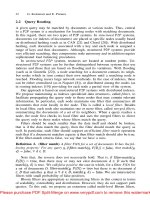
1.3.
1.4.
1.5.
1.6.
1.7.
1.8.
1.9.
1.10.
Aim of book
Classification of aircraft structures for inspection and repair
1.2.1.
1.2.2.
Repair requirements
I
.3.1. Repair levels
Repair procedures
The case for adhesively bonded repairs
Composite versus metallic patches
Scope of applications
Some experimental comparisons of bonding versus bolting
R&D
requirements
Conclusion
References
Design and certification of airframe structures
Problems with ageing metallic airframe components
Chapter
2.
Materials Selection and Engineering
R.
Chester
2.1. Introduction
2.2.
2.1.1. Factors affecting adhesion
Materials for patches and reinforcements
2.2.1. Metallic materials
2.2.2. Non-metallic materials
2.2.3. Patch material selection
2.3.1. Adhesive types
2.3.2. Adhesive properties
2.3.3. Adhesive selection
2.4. Primers and coupling agents
2.5. Adhesive and composite test procedures
2.6. Materials engineering considerations
2.6.1. Residual stresses
2.6.2. Cure pressure and voids
2.6.3. Spew fillet
2.6.4.
References
2.3. Adhesive systems
Composites offer the possibility
of
embedded strain sensors to
form “SMART” repairs
1
1
2
2
3
5
h
6
7
9
10
11
14
17
17
19
19
20
21
21
24
26
28
28
29
30
32
34
35
35
36
38
39
39
xiii
xiv
Contents
Chapter
3.
Surface
Treatment and Repair Bonding
D.
Amott, A. Rider and
J.
Mazza
3.1.
3.2.
3.3.
3.4.
3.5.
3.6.
3.7.
3.8.
3.9.
3.10.
3.11.
3.12.
Introduction
3.1.1.
Surface energy and wetting
3.1.2.
3.1.3.
Adhesive bond performance
3.1.4.
Mechanical tests
3.2.1.
Loading and failure modes
3.2.2.
Standard tests
3.3.1.
Wedge durability test
3.3.2.
Fundamentals of durable bonding
3.4.1.
3.4.2.
3.4.3.
3.4.4.
Bond durability model
Requirements
of
surface preparation
3.5.1.
Degreasing
3.5.2.
Abrasion, grit-blasting or etching
3.5.3.
3.5.4.
Coupling agent
3.5.5.
Adhesive primer
3.5.6.
Drying
Adhesive application
3.6.1.
Factors controlling bondline thickness
3.6.2.
Void formation and minimisation
Surface treatment quality control
3.7.1.
Waterbreak Test
3.7.2.
Surface work function methods
3.7.3.
Fourier transform infrared spectroscopy
3.7.4.
Optical reflectivity
3.7.5.
3.7.6.
Surface preparations for aluminium adherends
3.8.1.
Factory processes
3.8.2.
Surface preparations for titanium adherends
3.9.1.
Factory processes
3.9.2.
On-aircraft processes
Surface preparations for steel adherends
3.10.1.
Factory processes
3.10.2.
On-aircraft processes
Surface preparations for thermosetting-matrix composites
3.1 1.1.
Precured patches
Recent surface preparation research
3.12.1.
3.12.2.
References
Bondline pressurisation and adhesive cure
Standards and environments for adhesive bonding
Qualification of bonding procedures and performance
Fracture mechanics and the cleavage specimen
Surface roughness and bond durability
Surface hydration and bond durability
Surface contamination and bond durability
Creation of a high energy surface oxide
Process control coupons (traveller or witness specimens)
Practitioner education, skill and standards
On-aircraft acid anodisation and acid etch processes
Sol-Gel technology for adhesive bonding
Hot solution treatment
for
adhesive bonding
41
41
41
42
43
44
45
45
46
47
47
48
48
49
50
51
53
56
57
58
60
61
63
63
64
65
65
66
66
67
67
68
68
68
69
69
72
74
74
76
77
77
78
78
80
80
80
81
82
Contents
Chapter
4.
Adhesives Characterisation and Data Base
P.
Chalkley and A.A. Baker
4.
I.
Introduction
4.2.
Common ASTM and MIL tests
4.2.1.
Stress-strain allowables
4.3.
Fatigue loading
4.4.
Fracture-mechanics allowables
4.4.1.
Static loading
4.4.2.
Mode
I
4.4.3.
4.4.4.
Fatigue loading
4.5.1
4.5.2.
Yield criterion
4.5.3.
The glass transition temperature
4.5.4.
4.5.5.
Mode
I
fracture toughness
References
Mode
I1
and mixed mode
4.5. FM73
database
In situ shear stress-strain allowables
Fickean diffusion coefficients for moisture absorption
Chapter
5.
Fatigue Testing
of
Generic Bonded Joints
P.D.
Chalkley, C.H. Wang and A.A. Baker
5.1.
Introduction
5.1.1.
5.1.2.
5.2.1.
5.2.2.
Experimental method
5.2.3.
Experimental results
5.3.1.
5.3.2.
Experimental method and results
5.3.3.
Fracture mechanics approach
5.4.
Discussion
References
Damage-tolerance regions in
a
bonded repair
The generic design and certification process
Stress state in the DOFS
5.2.
The
DOFS
5.3.
The skin doubler specimen
Stress state in the skin doubler specimen
Chapter
6.
Evaluating Environmental
Effects
on Bonded Repair Systems
Using Fracture Mechanics
L.M. Butkus, R.V. Valentin and W.S. Johnson
6.1.
6.2.
6.3.
6.4.
6.5.
6.6.
Introduction
Materials and specimens
6.2.1.
Experimental procedures
6.3.
I.
Pre-test environmental conditioning
6.3.2.
Testing procedures
Analysis
Results and discussion
6.5.1.
Fracture toughness
6.5.2.
Fatigue behavior
Summary and conclusions
References
Bonded material system and fabrication
xv
87
87
88
89
94
94
95
95
96
96
98
98
99
99
100
100
101
103
103
103
104
104
106
108
109
1
I4
115
120
123
124
125
127
127
128
128
129
129
129
131
132
131
134
135
135
XVi
Contents
Chapter
7.
Analytical Methods for Designing Composite Repairs
L.R.F. Rose and C.H.
Wang
7.1.
7.2.
7.3.
7.4.
7.5.
7.6.
7.7.
Introduction
Formulation and notation
Load transfer of bonded reinforcement
Symmetric repairs
7.4.1. Stage
I:
Inclusion analogy
7.4.2.
7.4.3. Plastic adhesive
7.4.4. Finite crack size
7.4.5. Finite element validation
Shear mode
One-sided repairs
7.6.1. Geometrically linear analysis
7.6.2. Crack bridging model
7.6.3. Geometrically non-linear analysis
Residual thermal stress due to adhesive curing
7.7.1. Temperature distribution
7.7.2. Residual stress due localised heating
7.7.3. Residual stresses after cooling from cure
7.7.4. Thermal stress due to uniform temperature change
7.7.5. Validation
References
Stage
11:
Stress intensity factor
Chapter
8.
Recent Expansions in the Capabilities of
Rose’s
Closed-form
Analyses for Bonded Crack-patching
L.J.
Hart-Smith
8.1.
8.2.
8.3.
8.4.
8.5.
8.6.
8.7.
8.8.
8.9.
8.10.
8.11.
8.11.
8.12.
8.13.
Introduction
8.1.1.
8.1.2.
Universal efficiency charts for isotropic patches
Equivalence between octagonal and elliptical patch shapes
Effects of patch tapering on the adhesive stresses
Universal charts for the effects of corrosion
Design of patches to compensate for corrosion damage
Analysis of patches over cracks in stiffened panels
Designing to avoid crack initiation
Universal efficiency charts for orthotropic patches
Effects of residual thermal stresses on bonded repairs
Effects of adhesive non-linearity and disbonds on crack-tip stress-intensity
factors
Out-of-plane bending effects with one-sided patches
Remaining challenges involving closed-form analyses
Concluding remarks
References
Rose’s use of the inclusion model to establish stress fields
Rose’s solution for stress-intensity factor
K
at the crack tips
Chapter
9.
Numerical Analysis and
Design
R.
Jones
9.1. Analysis and design
9.2.
The 2D finite element formulation
9.2.1. Element stiffness matrix
137
137
139
141
144
144
147
149
150
154
155
157
157
162
163
167
168
170
171
173
173
I
74
177
177
178
180
183
184
186
189
191
192
194
196
197
200
202
204
204
205
207
207
208
210
9.3.
9.4.
9.5.
9.6.
9.7.
9.8.
9.9.
9.10.
9.11.
9.12.
Contents
9.2.2.
Initial design guidelines
Comparison with experimental results for non rib stiffened panels
Repair of thick sections
9.5.1. Experimental results
Repair of cracked holes in primary structures
Repair of cracked lugs
9.7.1. Numerical analysis
9.7.2. Experimental test
9.7.3. Discussion
Repairs to interacting surface flaws
Material nonlinearities
9.9.1.
Effect of variable adhesive thickness
9.10.1.
Repairs to cracked holes under bi-axial loading
Findings relevant to thick section repair
9.12.1.
References
Repair of cracks in aircraft wing skin
Governing differential equations for bonded joints/repairs
The effect of variable adhesive thickness and material non-linearity
Comparison of commercial finite element programs for the 3D
analysis of repairs
Chapter
10.
Shape
Optimisation
for
Bonded
Repairs
M.
Heller
and
R.
Kaye
10.1. Introduction
10.1.1.
10.1.2. Finite element modelling considerations
10.1.3. Outline of chapter
Analytical formulation for improved stepping in patch taper region
10.2.1.
10.2.2.
10.2.3.
10.2.4.
10.2.5.
10.2.6.
10.2.7. Numerical examples
10.2.8. Discussion
FE analysis for adhesive stress and plate stress concentration
10.3.1.
10.3.2. Results for no-fillet case
10.3.3. Results for fillet case
10.3.4.
Discussion of results
Gradientless FE method for optimal through-thickness shaping
10.4.1. Optimal adherend taper profile at the end of a bonded joint
Sensitivity FE method for optimal joint through-thickness shaping
10.5.1
Initial geometry, materials and loading arrangement
10.5.2. Optimisation method
10.5.3. Analysis for symmetric crack repair with aluminium patch
10.5.4. Analysis for non-symmetric crack repair with boron/epoxy patch
Optimal through-thickness shaping for F/A-18 bulkhead reinforcement
10.6.1. Initial geometry, materials and loading arrangement
10.6.2. Parameters for reinforcement optimisation analyses
10.6.3. Stress results for optimal reinforcement designs
Context for finite element based shape optimisation
10.2.
General configuration for symmetric stepped patches
Analysis for single step case
Analysis for patch with multiple steps
Estimate for optimal first step length
Minimum bound for peak shear strain due
to
patch length
Minimum bound for peak shear strain due
to
stiffness
of
first
step
10.3.
Configuration and finite element analysis method
10.4.
10.5.
10.6.
xvii
212
215
227
229
23
I
233
236
238
240
24 1
242
243
245
25
1
256
258
262
264
266
269
269
270
27
1
27 1
272
272
273
274
275
276
277
277
280
28
1
28
I
283
283
285
286
288
289
289
292
294
297
297
298
300
xviii
Contents
10.6.4. Discussion
Optimisation for F/A-18 aileron hinge reinforcement
10.7.1.
10.7.2. Shape optimisation before reinforcement
10.7.3. Iterative reinforcement design
10.7.4. Discussion
10.8.1.
10.8.2.
10.8.3.
10.8.4.
10.8.5. Analogy with hole-in-a-plate problem.
10.8.6.
10.8.7.
References
10.7.
Initial geometry, materials and loading arrangement
10.8. In-plane shaping effects
Geometry, loading and modelling considerations
Determination of
Kt
from FEA output
Uniaxial loading and patches with aspect ratios of 2:l
Uniaxial loading and other patch aspect ratios
Stress reduction at the centre of the patch for uniaxially loaded
plate
Summary of results and discussion
10.9. Conclusions
Chapter
11.
Thermal Stress Analysis
I
1.1. Introduction
11.2. Analytical expression for initial stresses in
a
circular plate due to heating
1
1.2.1.
11.2.2. Orthotropic solution
11.2.3.
1 1.2.4. Peel stresses
11.2.5.
Finite element thermal stress analysis
1
1.3.1. Two-dimensional strip joints
1
1.3.2. Three-dimensional strip joints
Application of analysis to large repairs of aircraft wings
1
1.4.1.
F.E.
analysis
11.4.2. Edge restraint factor
R.J.
Callinan
Comparison of F.E. and analytic results
Thermal stresses in
a
one-dimensional strip
Coefficients
of
thermal expansion of a laminate
11.3.
1
1.4.
11.5. Conclusions
11.6. Acknowledgment
References
Appendix
Chapter
12.
Fatigue Crack
Growth
Analysis
a
C.H. Wang
12.1. Introduction
12.2. Crack-closure analysis
of
repaired cracks
12.2.1. Small-scale yielding
Repaire Structures
12.2.2.
12.2.3.
Overload effect and validation using finite element method
Thermal residual stresses and comparison with experimental results
12.4.1. Thermal residual stresses
12.4.2.
References
Large-scale $elding solution for
a
stationary crack
Plasticity induced crack closure under large-scale yielding
solutions
12.3.
12.4.
Experimental results under spectrum loading
12.5. Conclusions
300
300
303
303
305
308
308
308
309
310
310
31
1
312
312
313
314
317
317
318
324
328
330
332
333
335
337
339
341
343
346
349
350
350
351
353
353
354
354
357
361
361
365
365
367
372
373
Contents
xix
Chapter
13,
Boronlepoxy Patching Efficiency Studies
A.A.
Baker
13.1.
Introduction
13.2.
Stress intensity analysis of patched cracks
13.2.1.
13.2.2.
13.2.3.
13.3.
Experimental approach
13.4.
Fatigue studies
13.4.1.
13.4.2.
Influence of stress range
13.4.3.
lnfluence
of
patch thickness
13.4.4.
Influence
of
R
ratio
13.4.5.
Influence of temperature
13.4.6.
13.4.7.
An approach to b/ep patch design
13.5.1.
Cyclic loading
13.5.2.
Spectrum loading
13.5.3.
Check on residual strength
References
Model for estimating stress intensity
Use of model
to
estimate crack growth
Extension
of
the model for growth of disbond damage
Disbond damage in the patch system
Influence of panel thickness variation
Residual strength of patched panels
13.5.
Chapter
14.
Glare Patching Efficiency Studies
R.
Fredell and
C.
Guijt
14.1
Introduction
14.1.1.
14.2.
Parametric studies of various patch materials
14.3.
Experimental results
14.4.
Discussion
14.5.
Summary and conclusions
References
Overview and background
of
fibre metal laminates
Chapter
15.
Graphitelepoxy Patching Efficiency Studies
P.
Poole
15.1.
15.2.
15.3.
15.4.
15.5.
15.6.
15.7.
15.8.
15.9.
15.10.
15.11
Introduction
Repair
of
thin skin components
Repair of thick sections
Graphitelepoxy versus boron/epoxy
Effect
of
bondline defects
Effect of impact damage
Effect of service temperature
Effect of exposure to hot-wet environments
Repair of battle damage
Future work
Acknowledgements
References
Chapter
16.
Repair
of
Multi-site Damage
R.
Jones and
L.
Molent
16.1.
Introduction
16.2.
Specimen and loading
375
375
376
376
378
379
379
381
38 1
383
384
384
386
387
389
392
392
394
396
396
399
399
399
400
408
410
412
413
415
415
416
418
424
427
433
435
436
438
440
440
441
443
443
444
xx
Contents
16.2.1.
Boeing lap joints
16.2.2.
Airbus lap joints
16.3.1.
Repair philosophy
16.3.2.
Repair details
16.4.1.
Thermo-elastic analysis
16.4.2.
Finite element analyses
16.5.1.
16.5.2.
16.5.3.
Environmental evaluation of repairs
16.5.4.
Hot/wet
16.5.5.
NaCl aqueous
Damage tolerant evaluation of specimens
16.6.1.
Adhesive disbonds
16.6.2.
Impact damage
16.6.3.
Tension testing
16.7.
Full scale repair demonstrators
16.7.1.
16.7.2.
16.7.3.
Doubler inspections
16.7.4.
Demonstrator summary
References
16.3.
Repairs
16.4.
Stress analyses
16.5.
Specimen fatigue test results
Unreinforced baseline fuselage lap joint specimens
Reinforced baseline fuselage lap joint specimens
16.6.
Airbus
A330/A340
fatigue test article
Boeing
727, 747
and
767
in-flight demonstrators
16.8,
Conclusions
Chapter
17.
Damage Tolerance Assessment
of
Bonded Composite Doubler
Repairs for Commercial Aircraft Applications
D.
Roach
17.1.
Introduction
17.1.1.
17.1.2.
Composite doubler damage tolerance tests
Conformity inspection and FAA oversight
17.4.1.
Fatigue tests
17.4.2.
Strain field measurements
References
Damage tolerance and fracture control plan
Damage tolerance establishes fracture control plan
17.2.
17.3.
17.4.
Test results
17.5.
Conclusions
Chapter
18.
Validation of Stress Intensity Estimations
in
Patched Panels
B.
Aktepe and A.A. Baker
18.1.
Introduction
18.2.
The K-gauge
18.3.
18.2.1.
K-gauge equations
Theory of
KI
measurement using strain gauges
18.3.1.
Westergaard equations
18.3.2.
18.3.3.
Wang’s crack-bridging model
Rose’s inclusion model for stress intensity
18.4.
Experimental procedure
18.5.
Strain surveys
18.5.1.
Unpatched specimen
444
449
450
45
1
452
453
453
456
459
459
464
464
465
466
468
468
469
472
474
474
477
479
480
480
482
485
485
486
488
49
1
492
500
500
506
514
515
517
517
518
518
519
519
52
1
52
1
522
524
524
Contents
18.5.2.
Patched specimen
18.6.
Crack length
18.7.
Time-dependent behaviour
18.8.
Conclusions
18.9.
Nomenclature
References
Volume
2
Chapter
19.
Bonded Repair
of
Acoustic Fatigue Cracking
R.J.
Callinan and S.C. Galea
19.1.
19.2.
19.3.
19.4.
19.5.
19.6.
19.7.
19.8.
19.9.
19.10.
19.11.
Introduction
Cracking history
19.2.1.
Inlet nacelle
19.2.2.
Aft fuselage cracking
Sound pressure levels
19.3.1.
Inlet nacelle
19.3.2.
Aft fuselage
19.3.3.
Power spectral density
Random response analysis
Stress intensity factors
FEA of cracked nacelle inlet
19.6.1.
Crack growth study
19.6.2.
Highly damped repairs for cracked panels
19.7.1.
19.7.2.
19.7.3.
19.7.4.
Results and discussion
Aft fuselage finite element model
19.8.1.
Modes and frequencies
19.8.2.
19.8.3.
Residual thermal stresses
19.8.4.
Damping data
19.8.5.
Adhesive data
Thermal environment for
F/A-18
Analytical results
Experimental work
Summary of repair failure investigation
Design of highly damped patch
Damping of highly damped patch
Analysis of repaired cracked plate
Acoustic fatigue crack growth data
19.12.
Conclusions for aft fuselage repair
References
Chapter
20.
Smart Patch Systems
20.1.
Introduction
20.2.
Smart patch approach
20.3.
Damage detection studies
S.C. Galea
20.3.1.
Load transfer (strain) technique
20.3.2.
Residual strain technique
20.3.3.
20.3.4.
Laboratory smart patch conceptional demonstrators
Electro-mechanical impedance, transfer function and stress wave
technique
Adhesive bond degradation sensors
-
active sensing technique
20.4.
xxi
525
526
527
529
529
530
53 1
531
533
533
536
536
536
536
537
537
538
539
540
546
546
547
547
55
1
55 1
557
558
559
560
56
1
56
1
562
563
566
568
568
57 1
57 1
573
578
578
588
593
597
599
xxii
Contents
20.5.
In-flight demonstrator
20.5.1.
20.5.2.
Health monitoring systems
References
Finite element analysis
-
damage sensing technique
20.6.
Conclusions
Chapter
21.
Adhesively Bonded Repairs: Meeting the Safety Requirements
Implied within Existing Aviation Industry Certification Regulations
D.
Bond
21.1.
21.2.
21.3.
21.4.
21.5.
21.6.
21.7.
21.8.
Introduction
Certification of an adhesively bonded repair
21.2.1.
21.2.2.
Adhesively bonded repairs
21.2.3.
Regulatory deficiencies
Repair design information
21.3.1.
Existing requirements
21.3.2.
Additional guidance
Analysis and development testing
21.4.1.
Design allowables
21.4.2.
Static analysis
21.4.3.
21.4.4.
Development testing
Full scale testing
21.5.1.
Existing requirements
In-service management and inspection
21.6.1.
Existing requirements
21.6.2.
Additional guidance
Future approaches to bonded repair certification
Conclusions
References
The need to certify a repair
Fatigue and damage tolerance analysis
Chapter
22.
Certification Issues for Critical Repairs
A.A. Baker
22.1.
22.2.
Current limitations of crack patching
Justifying credit
for
patching efficiency
~
fatigue concerns
22.2.1.
22.2.2.
22.2.3.
Validation of patching analysis
Justifying credit for patching efficiency
~
environmental durability concerns
22.3.1.
22.3.2.
Justifying credit
for
patching efficiency
-
the Smart Patch approach
Influence of fatigue on patching efficiency
Obtaining patch system fatigue allowables
22.3.
Assurance of patch system environmental durability
Australian experience on service durability
22.4.
22.5.
Discussion
22.6.
Conclusions
References
Chapter
23.
Nondestructive Evaluation and Quality Control
for
Bonded Composite
Repair of Metallic Aircraft Structures
D.P.
Roach and
C.M.
ScaIa
23.1.
Introduction
23.1.1.
NDI needs and damage tolerance
604
604
607
61
1
612
615
61
5
617
617
617
618
619
619
62 1
62
1
62
1
626
630
635
637
637
637
637
637
638
638
639
643
643
644
645
646
648
648
650
653
654
655
656
656
659
659
660