Nghiên cứu ứng xử cắt của dầm bê tông cường độ cao cốt sợi thép TT TIENG ANH
Bạn đang xem bản rút gọn của tài liệu. Xem và tải ngay bản đầy đủ của tài liệu tại đây (1.86 MB, 27 trang )
MINISTRY OF EDUCATION AND TRAINING
UNIVERSITY OF TRANSPORT AND COMMUNICATIONS
TRAN THI LY
RESEARCH ON SHEAR BEHAVIOR OF HIGH STRENGTH
FIBER REINFORCED CONCRETE BEAMS
Field of study: Transport Construction engineering
Code : 9580206
Major: Technical technology Construction of special works
SUMMARY OF DOCTORAL THESIS
HANOI - 2022
download by :
This research is completed at:
UNIVERSITY OF TRANSPORT AND COMMUNICATIONS
Supervisors:
1. Assoc. Prof. Pham Duy Anh
2. Assoc. Dao Văn Dinh
Reviewer 1: Prof.Dr.Sc.
Reviewer 2: Prof.
Reviewer 3: Assoc. Prof.
This thesis will be defended before Doctoral-Level
Evaluation Council at University of Transport and Communications
at …..hours……Day……Month……Year…….
The thesis can be found at:
- Vietnam National Library
- Library of University of Transport and Communications
download by :
1
INTRODUCTORY
1. Question
High-strength concrete (HSC) has a large compressive strength, but the
tensile strength is still very small. In addition to increasing the
compressive strength, the tensile strength of concrete also needs to be
improved to increase the bearing capacity of concrete and reinforced
concrete structures. To increase the tensile strength of concrete, it is
common to use dispersed fiber reinforcement as a component of the
aggregate in the concrete mix. Steel fiber reinforcement (SFR) is one of
the most commonly used types of fiber reinforcement. Steel fiber
reinforcement has the role of increasing tensile strength for concrete
and high strength concrete. Thereby increasing the contribution of the
tensile region to the shear strength of the reinforced concrete beams. In
order to increase the shear strength of reinforced concrete beams, in
addition to using traditional stirrups, oblique reinforcement,
reinforcement made from new materials such as composite
reinforcement, carbon fiber reinforcement, carbon stickers plate …
were also applied. The reinforcement bars enhance the shear resistance
for beams significantly, however, using steel bars to reinforce shear
resistance for beams will face some problems such as: Only increase
the bearing capacity in the direction of the reinforcement; When using
large diameter, the adhesion is not good, the distance of the
reinforcement bars is too close, leading to difficulty in construction and
erection, difficult to pour concrete, expensive production costs, etc., so
using dispersed steel fibers to be inserted into the base phase of the
project. SFR increasing shear strength for beams is a new trend.
Research on shear behavior of steel fiber reinforced concrete beams
(SFRC) has been interested by many scientists around the world. Shear
behavior of steel fiber reinforced concrete beams is always a
complicated issue. Shear failure is derived from inclined cracks caused
not only by the shear force but also by the combination of shear force
with bending moment, torque and axial force. Shear failure depends on
many factors such as size, geometrical characteristics, load effects and
structural properties of the structural materials. The comprehensive
study of the shear behavior of SFRC beams helps scientists to come up
with a more accurate calculation model. In particular, the study of the
shear behavior of SFRC beams using stirrups is a complicated topic that
has not been studied much. The topic of shear behavior of SFRC beams
download by :
2
needs more attention. Stemming from that fact, the thesis proposed and
implemented a topic called: "Study on shear behavior of high-strength
steel fiber reinforcement concrete beams"
2. Ressearch purposes
- Research on the theory of shear behavior of SFRC beams and
reinforced concrete beams in particular, thereby selecting a semiempirical model suitable for the calculation of shearing for reinforced
concrete beams with reinforced concrete.
- Research and develop a formula for predicting the shear resistance of
Hight strength SFRC beams, survey the factors affecting the shear
resistance of Hight strength SFRC beams.
- Provide the shear design sequence for the SFRC beams subjected to
the design load in the Standard of Road Bridge Design TCVN 118232017
- Experimental study to verify the proposed formula, study the types of
shear failure in the Hight strength SFRC beams and study the
deformation in the longitudinal reinforcement, the stirrups and in the
concrete in the compression domain of the simple Hight strength SFRC
beam.
3. Object and scope of the study
Shear behavior of simple SFRC girder. The design compressive
strength is 70MPa. The content of fiber reinforcement ranges from
0.5%-2%. Dramix steel fibers, double crochet hook with variable
length. Dramix steel fiber reinforcement is a common type of steel fiber
and has been applied to reinforced concrete structures in Vietnam.
4. Research Methods
Method of combining theory and experiment in the room.
5. Scientific and practical significance
The research results of the thesis contribute more to a model to
calculate the shear resistance for high-strength concrete beams with
steel fiber reinforcement, which helps researchers and designers to refer
to their work.
6. The structure of the topic
The thesis topic includes an introduction, 4 main chapters, conclusions,
recommendations and directions for further research, list of references
and appendices
download by :
3
Chapter1. OVERVIEW OF STEEL FIBER REINFORCED
CONCRETE AND STEEL-REFIED CONCRETE
CONSTRUCTION BEAM CUTTING BEHAVIOR
1.1. Development history of reinforced concrete
Around the world, from the period of Egypt and Babylon, people
have used fibers or animal hair to strengthen bricks, plaster walls,
plaster. With Portland cement mortar, people use asbestos fibers. The
first studies on dispersed steel fibers were by Romualdi, Batson,
Mandel. Subsequent research was carried out by Shah and Swamy and
several others in the US, UK and Russia. In the 1960s, SFRC began to
be used in pavement structures.
In the years 1989 - 1999, the standards of ACI 544 on fiber
reinforced concrete were born, including 4 volumes: 1R overview, 2R
properties, 3R technology introduction, 4R-99 guide design guidelines
for SFRC. Up to now, there has been a set of 9R- forecasting based on
measuring mechanical properties of rigid fiber reinforced concrete. The
standards have included the calculation content of SFRC structures
such as ACI, DIN, AASHTO, EHE, Fib from 1988 to present.
In Vietnam, research on manufacturing fiber-reinforced concrete,
steel fiber as well as studies on properties of steel-reinforced concrete
by authors such as Tran Ba Viet, Nguyen Thanh Binh and Pham Duy
Anh has been carried out, published in prestigious journals of the
Industry. Researches on fabricating fiber-reinforced concrete based on
local materials by Ho Chi Minh City University of Science and
Technology and for Traffic works by the Institute of Transport Science
and Technology have also contributed to the development of this
material in Vietnam. The issues of ecological construction were
initially interested and published in 2003 with the book "Steel fiber
Reinforced concrete" edited by author Nguyen Viet Trung. Researches
on the mechanical properties and behavior of SFRC structure have also
been studied by the authors in their doctoral thesis from 2000 up to
now.
1.2. Mechanical Features of SFRC
Steel fiber reinforced concrete is a composite material, which
improves the behavior of ordinary concrete after cracking. The
properties of concrete after cracking depend greatly on the adhesion
force between the fiber reinforcement and the concrete. The main role
of steel fiber reinforcement is to stitch cracks, limit crack expansion,
download by :
4
make SFRC more flexible and absorb more energy than ordinary
concrete. Steel fiber reinforcement increases the tensile strength of
concrete. The greater the adhesion force between the steel fiber and the
concrete, the greater the tensile strength of the reinforced concrete
because the reinforcement is difficult to pull out of the concrete.
According to Lim et al. The tensile strength of fiber-reinforced concrete
is 2-3 times greater than the tensile strength of the sample without steel
fiber when the fiber content is 1% and 1.5%. The compressive strength
of concrete does not increase significantly when using dispersed steel
fiber reinforcement. The research results at the University of Transport
on the reinforced concrete beam structure show that the tensile strength
when bending increases by 15-20%. Lim et al. confirmed that with steel
fiber content from 0%-2%, the shear strength of reinforced concrete
increases to 100% compared to normal concrete.
1.3 Overview about researh on shear behavior of SFRC beams in
the world and Vietnam
In the world, from the 80s of the 20th century up to now, there have
been many researches on the shear behavior of fiber reinforced concrete
beams (SFRC) in general and SFRC slabs in particular. In which,
SFRC beams have been interested by many scientists around the world.
The research method on shearing of SFRC beams in the world today is
mainly theoretical research combined with experiment or research
based on the shear resistance calculation equations in the current
standards. Some studies are completely experimental to provide a
model to calculate the shear resistance of reinforced concrete beams.
*) Researching method for calculating shear resistance of SFRC beams
in current standards in the world:
The equation in the current standards are based on experimental
or semi-empirical studies by previous scientists. To calculate the shear
resistance of SFRC beams according to the models calculated in the
current standards, a lot of input test parameters are needed. In the
RILEM TC62 TDF standard to calculate the shear strength SFRC
beams needs the input parameters which are the characteristic flexural
tensile strengths through the beam sample bending test. In the ACI
standard 544-4R 88, to be able to calculate the shear resistance of the
SFRC beams, it is necessary to have the tensile strength parameters
directly or indirectly through testing… The experimental parameters
download by :
5
are sometimes not available, so it is difficult to meet the requirements.
Many difficulties for predicting the shear strength of SFRC beams,
especially when experimental data are not available.
Theoretical and experimental study of shear behavior of
reinforced concrete beams without using reinforcement
The initial studies on shearing of SFRC beams focused on
investigating the influence of factors such as fiber shape, fiber content
and the ratio between the distance of the force application to the
effective height of the beam (referred to as the ratio for short. cutting
span and effective height). Some studies, based on theoretical and
experimental methods, have proposed formulas for calculating average
shear stress on beam cross-section (νu).
Previous studies have shown that steel fiber reinforcement contributes
greatly to the shear strength of SFRC beams. The authors study on the
influence of content and other factors on shear resistance such as:
Sharma, Narayanan and Darwish, Naaman et al., Lim and Oh, K. S.
Elliott, C. H. Peaston and K. A. Paine; Joaquim A.O. Barros and Lucio
A.P.Lourenỗo Simao P.F. Santos; Yoon Keunt Kwak, Mack O.
Eberhard, Woo-Suk Kim, and Jubum Kim; Two Palaces; Gustavo J.
Parra-Montesinos, M.ASCE and James K. Wight suggested that the
average shear stress in the SFRC beam is 0.33√f'c (MPa) when the
reinforcement content is 0.75% - 1.5 %. Experimental research on
building models of shear resistance by authors such as Narayanan and
Darwish; Yoon Keunt Kwak, Mack O. Eberhard, Woo-Suk Kim, and
Jubum Kim used the test results from the collected 139 SFRC beams to
develop a formula for calculating the mean shear stress of the SFRC
beam. The authors Emma Slater, Moniruzzaman Moni, M. Shahria
Alam experimentally studied 222 fiber-reinforced concrete beams
without reinforcement. The authors have built a formula to calculate the
average shear strength of beams by linear and non-linear regression
methods for reinforced concrete and reinforced concrete beams. In the
calculation model, a quantity that needs to be determined through
experiment is the adhesion force between the steel fiber reinforcement
and the concrete. The adhesion force between steel fiber reinforcement
and concrete is a parameter that depends on fiber shape, fiber length as
well as concrete grade. It would be difficult without experimental data
on this parameter.
Theoretical and experimental study of the behavior of SFRC
download by :
6
beams using stirrups
Around the world, there have been a number of authors studying the
behavior of reinforced concrete beams using stirrups. Studies often use
computational models available in current standards. Esefanía Cuenca in
her thesis in 2014, used the shear resistance calculation model in EHE-08
standard and proved that steel fiber reinforcement can replace all or part of
the reinforcement in beams. The study of fiber reinforcement content,
assessment of the contribution of fiber in SFRC beams and the behavior of
beams using stirrups is very large. However, the author does not research
only for high-strength steel fiber concrete (HS SFRC) beams and also does
not build a computational model for HS SFRC beams. The authors all
have the same conclusion that in girders with stirrups, steel fiber
reinforcement increases shear resistance more than girders without
reinforcement when having the same fiber reinforcement content. Daniel
de Lima Araújo, Fernanda Gabrielle Tibúrcio Nunes, Romildo Dias
Toledo Filho and Moacir Alexandre Souza de Andrade have compared
two types of fiber-reinforced concrete beams without stirrups and with low
stirrups content (0.21%). Fibered content from 1% to 2%. The authors
used control beams without fiber reinforcement. The results show that,
when increasing the amount of fiber in the girder without reinforcement,
the critical shear force increases less than when using the girder with
reinforcement. Meda, Minelli and Plizzari have experimentally studied on
prestressed reinforced concrete beams with large I-section (real beam size),
I-section with 0.64% fiber content. Using reinforcement, it has been shown
that fiber reinforcement significantly increases the shear resistance of
beams.
In addition to considering the contribution of steel fiber
reinforcement, the authors also believe that steel fiber reinforcement can
replace the minimum reinforcement.
From the review of shear behavior studies in the world, it is
shown that there are not many studies on high-strength concrete beams
with steel fiber reinforcement. Very few studies have built a model to
calculate the shear resistance for only reinforced concrete beams with steel
fibers, especially girders using stirrups. From the above analysis, the thesis
focuses on solving the following issues:
Studying the mechanical properties of HS SFRC, especially the
tensile behavior of the HS SFRC because it will serve to calculate the
shear resistance of the HS SFRC beams.
Studying experimental models, theoretical models and standard
models in the world, from which to choose a suitable model for SFRC
download by :
7
girders;
Experimental study to determine the relationship formula between
tensile stress after cracking of HS SFRC with fiber content and other
parameters, thereby finding out the contribution of steel fiber reinforcement
to tensile stress after the concrete is cracked;
Research and propose formula for predicting shear resistance for
HS SFRC beams; Research on beams of design dimensions to verify the
formula in the proposed thesis; thereby evaluating some behaviors of the
HS SFRC beams such as evaluating the force relationship and deflection
between spans; the behavior in concrete in the compression domain,
deformation in the main longitudinal reinforcement and the reinforcement
by connecting the output device.
Research and propose the design sequence of shearing for SFRC
beams under the effect of road bridge loads.
Chapter 2. RESEARCH AND BUILDING MODEL FOR
FORECASTING SHEAR RESISTANCE OF SFRC BEAMS
2.1. Destruction and shear force components of SFRC beams
2.1.1. Destruction of SFRC beams
For SFRC beams that do not use stirrups, fiber reinforcement acts as
the stirrups in the beam. Steel fiber reinforcement can redistribute the
tensile stress in the beam, slow down the propagation and widen the
inclined crack. Prevents concrete splitting along the main longitudinal
reinforcement bar. The fiber reinforcement controls the crack width and
promotes the formation of microcracks. With that clear role, the
deformation stiffness and bearing capacity of the beam are enhanced.
The analysis of shear strength in reinforced reinforced concrete beams
faces many challenges. The most important issue related to the
reinforcement of fiber reinforcement is their proper distribution to form
uniform mechanical properties. In addition, the widening of the inclined
crack in the SFRC beams is caused by the steel fiber reinforcement
being pulled instead of the ductile reinforcement in the conventional
reinforced concrete beams.
2.1.2. Participating components are subjected to shear forces.
The components participating in the shear stress of the reinforced
concrete beam include: The transmission of shear forces in the
uncracked concrete area of the beam (Vcc); The transmission of surface
shear forces due to the interlocking of aggregates and the roughness of
the surface along the fracture. inclined cracking (Va); Transmission of
download by :
8
shear force through the dowel effect of longitudinal reinforcement
(Dowel Action) (Vd); Transmission of shear through residual tensile
stresses in inclined cracks (Vcr); The transmission of shear forces
through the shear reinforcement (Vs); Vertical component of the
prestress force (Vp).
For SFRC beams, in addition to the above components, there is also the
participation of shear force transmission of steel fiber reinforcement
(Vf).
2.1.3. Factors affecting the shear resistance of SFRC beams
There are many factors affecting the shear resistance of SFRC
beams such as: the ratio between the distance from the point of
application of the force to the bearing and the effective height (ratio
a/d); Effect of beam size; Effect of compressive strength of SFRC (fc');
Effect of steel fiber reinforcement content; Effect of longitudinal
reinforcement content (ρ); Effect of fiber shape and size. In which the
steel fiber content is the factor that has the greatest influence on the
shear resistance of the reinforced concrete beams
2.2. Models for predicting shear resistance of SFRC beams
Models in the current standards
In which, some standards have proposed to calculate the shear
resistance of beams according to experimental models, others based on
theoretical and experimental models. Models in standards such as: ACI
544-4R88, RILEM TC 162, fib MODEL CODE 2010, EHE-08, DIN1045-1, MC2010… have proposed formulas for predicting shear
resistance of SFRC beams with or without reinforcement.
Experimental model:
There are many authors in the world who have experimentally
researched and built predictive models of shear resistance SFRC beams,
but the empirical models are often very simple and ignore a number of
secondary factors. One of the models that simply predicts the shear
resistance of normal strength SFRC beams without reinforcement is
proposed by Sharma.
However, it is necessary to more fully evaluate the factors affecting the
shear resistance. It is very expensive to build such a model purely
experimentally because of the extremely large number of test samples.
Semi-empirical model.
Semi-empirical models such as: Modified compression field theory
(MCFT), fixed angle soft truss model (FA-STM) and Rotating Angle
Softened Truss Model (RA-STM), Sliding crack model (Crack Sliding
download by :
9
Model-CMS)… has been applied by researchers to calculate shear for
SFRC beams and HS SFRC beams. The perturbation stress field model
(DSFM) introduced by Vecchio has also been used by the author in
applying shear calculations to compare with experiment. Other methods
such as numerical method, simulation method have also been applied to
calculate SFRC beams. Nowadays, some authors have proposed the
method of Artificial Neural (ANN-8; ANN-10) to predict the shear
resistance on inclined cross section…
One of the semi-empirical models that is theoretically rigorous and
consistent with the behavior of SFRC materials is the simple modified
Compression Field model. This model has been selected by the analyst
to calculate the shear for the reinforced concrete beams of SFC.
2.3. Building a model to calculate shear resistance of HS SFRC
beams.
2.3.1 Theoretical basis
Modified Compressive Field Model (MCFT) or Simple Modified
Field (SMCFT) is a suitable semi-empirical model that has been
selected to predict the shear resistance for SFRC beams. In particular,
using the MCFT model to calculate the shear for SFRC girders is more
suitable due to its rigor. The equations in the MCFT model considered
the relationships between strain stress, strain compatibility, and force
equilibrium conditions. The contribution of steel fibers to the shear
strength in the MCFT model can be considered independently.
Based on the force balance in the MCFT model at the inclined
section considered in the reinforced concrete beam, the average shear
stress is established as equations (2 70) and (2 69) for the two cases
mentioned above.
for a/d≥2.5;
(2-69)
v f c ' f cot z f szcr cot ,
v 2.5d / a[
f c ' f cot z f szcr cot ] , for a/d<2.5;(2-70)
Therefore, it is necessary to study experimentally to determine the
value of the residual tensile stress after cracking of reinforced concrete
(σf ) by split compression test
2.3.2 Experimentally building a model to calculate the residual
tensile strength (σf).
The execution is carried out in the following order
- Determine the objective function and influencing factors
- Determine the number of samples and plan the experiment
download by :
10
- Conduct experiments
- Synthesize and analyze test results
- Determine and evaluate the regression correlation between the
objective function and the input variable.
Build an objective function related to the input parameters so that the
closest representation to the experimental data set. This equation is
called the regression equation. At the basic level, we use the first-order
regression equation. Therefore, the objective function here is the
relationship function between the shear strength (fsp) and the steel fiber
content (Vf). Other parameters such as fiber shape ratio (Lf/Df) and
compressive strength of concrete (f'c) are considered fixed.
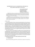
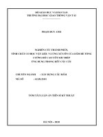
The split compression test was conducted with a number of 126
samples, including 105 samples for determining the splitting strength
and 21 samples for compressive strength. The design grade cỏncrete is
70MPa. Two types of fiber with different lengths include: short Dramix
3D 65/35 BG and long Dramix 3D 80/60 BG. The four fiber contents
considered are: 0%, 0.63%, 1% and 1.5%. Samples are denoted with
the following characters: Mi sample i, C70 is concrete grade 70 MPa,
CP1: corresponds to fiber content of 0.63%, CP2- stands for 1% fiber
content and CP3- has a fiber content of 1.5%. S1 - is for short fiber, S2
is for long fiber. The order of
symbols is arranged as follows:
C70CP0-S1. Thus, there are 7
types of concrete mix. The
composition of the SFRC levels
of 70Mpa level is designed as
shown in Appendix 1.
The number of test samples
for each mix grade and the
sample size for each sample
group are as shown in Table 2.4.
download by :
11
The experimental results were analyzed statistically, the probability
density function of the test samples corresponding to the cases of no
fiber, short fiber and long fiber with different fiber content is shown in
Figure 2.27, Figure 2.28. and Figure 2.29
StDev
0.8135
0.3259
0.5231
0.6115
N
15
15
12
12
0.6
0.6
Mean
5.679
8.484
9.401
11.39
0.5
0.4
StDev
0.8135
0.6956
0.5639
1.184
N
15
15
12
12
Variable
N-0 .6 3 %
N-1%
N-1.5 %
D-0 .6 3 %
D-1%
D-1.5 %
1.2
1.0
0.8
M ật độ
Mean
5.679
6.929
8.201
10.15
0.8
Variable
0%
D-0 .6 3 %
D-1%
D-1.5 %
0.7
M ật độ
1.0
M ật độ
0.8
Vari abl e
Không sợi
N-0 .6 3 %
N-1%
N-1.5 %
1.2
Mean
6.929
8.201
10.15
8.484
9.401
11.39
0.6
0.3
0.4
0.4
StDev
0.3259
0.5231
0.6115
0.6956
0.5639
1.184
N
15
12
12
15
12
12
0.2
0.2
0.2
0.1
0.0
4
5
6
7
8
9
10
11
Cường độ é p chẻ (M Pa)
Figure 2.27. Normal
distribution function
of split compressive
strength of fiberless
and short fiber
samples
0.0
4
6
8
10
12
0.0
14
Cường độ é p chẻ (M Pa)
6
8
10
12
14
Cường độ é p chẻ (M Pa)
Figure 2.28. Normal
distribution function
of split compressive
strength of fiberless
and long fiber samples
Figure 2.29. Normal
distribution function
of split compressive
strength of short and
long fiber samples
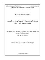
Regression results found that the coefficients A and B for the two
cases of reinforcing steel fibers are short fibers (Lf/Df = 63.63) and long
fibers (Lf/Df = 80) shown in Figure 2.30 and Figure 2.30. 2.31. The
equations with the large R2 correlation coefficient are R2 = 86.3%
(short fiber), R2 = 86.0% (long fiber) respectively, and these values are
all greater than 80%. This shows that the regression models are suitable
and completely statistically significant.
fsp=5.426+2.950Vf
Figure 2.30. Data processing
results of samples using short
fibers (lf/df=63.63)
fsp=5.813+3.755Vf
Figure 2.31. Data processing
results of samples using long
fibers (Lf/Df=80)
Add the remaining parameters such as concrete strength, fiber size
download by :
12
ratio into the regression equation, the post-cracking tensile strength of
the reinforced concrete for both cases according to the proposed thesis
as shown in equation (2 - 81)
L
(2-82)
f 0.37 f f f 'c
Df
The model for calculating the shear resistance of the proposed SFRC
beams. From the experimental results to determine the residual tensile
strength (after cracking) of the high-grade concrete as equation (2-82),
replace this equation in (2 68) and (2 69), the thesis gives the formula
forecast shear resistance of reinforced concrete beams of CST as (2-85).
To take into account the effects of beam and arch effects, if the ratio a/d
< 2.5, the formula is multiplied by 2.5d/a as shown in equation (2-86).
L
Vn ( fc ' 0.37 f f fc ' cot z f szcr cot )bv dv , khi a/d ≥ 2. 5 (2 85)
Df
Vn 2.5d / a( fc ' 0.37 f
Lf
Df
fc ' cot z f szcr cot )bv dv
khi a/d < 2.5; (2-86)
CONCLUSION CHAPTER 2
Selecting a semi-empirical model to predict the shear resistance of
SFRC beams is very important. The semi-empirical model needs to
predict relatively accurately the shear resistance of SFRC beams and
the reinforced concrete beams. Therefore, the Modified Compression
Field model simply was chosed because of its suitability.
- In the simple modified compression field model, the quantity
participating in the formula for calculating the shear resistance of SFRC
beams is the main tensile stress (f1). Contribution to the main tensile
stress consists of two components: the component due to concrete and
the contribution of steel fiber reinforcement.
- The factors affecting the post-cracking tensile strength of reinforced
concrete are fiber content, fiber shape, fiber length and concrete grade. In
which, fiber content is an important factor that greatly affects the tensile
strength of SFRC. Therefore, building a function of tensile strength
depending on fiber content and other parameters to evaluate the contribution
of steel fiber reinforcement to shear strength was performed. Due to the
difficulty of pulling the SFRC sample directly, the standard cylindrical
compression test was performed.
- Postgraduate uses 2 types of fibers as described above, with
download by :
13
variable fiber content, to design the composition for 70MPa highstrength concrete mix. Adjust the composition for 7 SFRC mixes and
cast 105 samples for splitting and 21 samples to test the compressive
strength of each calculated grade.
- Based on the experimental results of split compression with 105
samples of HS SFRC, has built a formula to calculate the tensile
strength of HS SFRC after cracking as formula (2- 82).
- Combined with the model to calculate the shear resistance of
SFRC beams selected in section 2.2.3, the researcher has built a
formula to calculate the shear resistance HS SFRC beams for 2 cases
a/d ≥ 2.5. and a/d < 2.5 as in (2 85) (2 86).
Chapter 3. EXPERIMENTAL RESEARCH SHEAR
BEHAVIOR OF SFRC BEAM
3.1. Experiment target
Chapter 3 conducts an experimental study on the shear behavior of
reinforced concrete beams of the design size to verify the model
proposed by the researcher and evaluate the behavior in the HS SFRC
beams including cracking angle, deformation in compacted concrete,
and deformation form in longitudinal reinforcement and stirrups under
load until failure. The girder size is selected to match the jacking
capacity and design standards.
The 4-point bend beam model used for testing the reference beam
according to ASTM C78 [39]
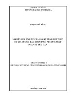
3.2. Design of experimental beams
Beam size
The beam structure
must be designed so that only
shear failure is not caused by
bending (Figure 3.2). The girder
size is selected so that the
device can bend and break the
beam. The beam bending test
was carried out at the
Engineering Experiment Center
Figure 3.2 Arrangement of
reinforcement and measuring
of the University of Transport.
positions for strain and
deflection when bending the HS
SFRC
download by :
14
3.3. Calculate the shear resistance of the test beams according to
the proposed model and investigate the influencing factors
Forecasting shear
strength of reinforced
concrete beams and
surveying fiber content
Using the proposed
model, calculate the shear
resistance of HS SFRC
beams. Calculation of
shear resistance for beam
h=400mm. Investigate the
shear resistance of HS
SFRC beams with dimensions as mentioned in the above section. Using
Dramix fiiber Lf/Df=35/0.55=63,636, with fiber content of: 0%, 0.63%,
1%, 1.5%, respectively. The results show that the shear strength of
beams increases greatly with increasing fiber content (Table 3.3).
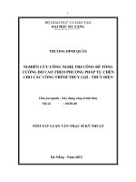
The fiber length has an
influence on the shear
strength of SFRC beams,
according to the survey of
large fiber lengths, the shear
resistance of HS SFRC
beams increases as shown in
Figure 3.4.
3.4. Calculation of test Figure 3.4. 70MPa SFRC beam shear
load
resistance when using short fibers
Calculation of test loads for
(65/35)
the purpose of predicting
beam breaking loads due to
shea r. From there, consider
the jacking capacity of the
beam bending device. From
there, it is decided to choose
equipment with suitable
capacity to destroy the test
beam. Calculation results as
in table 3.5.
download by :
15
3.5. Conduct testing Fabrication of beams
Figure 3.5 Construction of formwork for casting HS SFRC
beams
Conduct beam bending
The
beam
bending
device must
have a jacking
capacity
greater than
the maximum
internal load
causing shear
failure
as
shown in table
3.6.
Equipment at
the University
of Transport
meets
the Figure 3.7 Construction of formwork for casting SFRC
beams Conduct beam bending
above
requirements.
Use a jacking device with a
capacity of 100T to
increase the load. To
measure the load acting on
the beam, a load cell placed
on the top of the beam is
used as shown in Figure
3.8. The deflection sensor
head is mounted in the
middle of the span, the
front of the beam and
connected to the dosing device. The strain gauges in concrete,
longitudinal reinforcement and belt as shown in Figure 3.2 are
connected to the measuring device. Beams are loaded according to each
download by :
16
level. Loading rate according to the relationship of load (P) and strain.
3.6. Results and analysis of results
Shear resistance of test beam
Table 3.7 is the data of the load measured when the beam fails and the
experimental shear resistance, compared with the shear resistance
calculated according to the model proposed in chapter 2. The results show
that the experimental beam shear resistance is higher than that of the shear
strength. with calculation. However, it is not too large. The results show
that there is a similarity between theory and experiment. The beam failure
model is also expected. Inclined cracks usually begin to crack from the
middle or from the tension zone, grow to the compression zone, and then
the beam breaks. Use the ACI standard 544R88 for further control
comparison.
Comparison
results
as
in
table
3.6
Analysis of destructive patterns
All beams show inclined cracks and failure due to shear bending.
For reinforced concrete beams without steel fiber reinforcement, only
main inclined cracks appear, when failure at that crack, the crack width
is larger. In addition to the main crack, many inclined cracks of smaller
width appear near the main crack. The angle of inclination of the crack
is smaller than that of the beam crack without reinforcement.
download by :
17
Figure 3.9 Crack model in beam bending
Beam B-0-300-6-300
Figure 3.10 Crack model in beam
bending Beam B-0.63-300-6-300short fiber
Figure 3.11. Crack model in beam
bending Beam B-1-300-6-300- short fiber
Figure 3.12. Crack model in beam
bending Beam B-0.63-300-6-300-long
fiber
Figure 3.13 Crack model in beam bending
Beam A-0-300-6-300
Figure 3.14. Crack model in beam
bending Beam B-0.63-300-6-300short fiber
Analysis of load relationship and deflection between spans
Figure 3.15. Graph of relationship between load and deflection
between beam span H400mm
download by :
18
Analysis of load relationship and deformation of concrete under
compression
Figure 3.16. Graph of internal load and deformation in concrete
in compression beam H400mm
Remarks, the graphs are relatively linear, concrete works in the
elastic period. Using steel fiber reinforcement with higher content, the
greater the plasticity in compressive strength of reinforced concrete and
the larger plastic deformation in concrete in the compression domain at
failure
Result of strain measurement in longitudinal reinforcement
The graphs in Figure 3.17 and Figure 3.18 show that, because beams
B0-300-6-300 do not use steel fiber reinforcement, the main
longitudinal reinforcement quickly melts when the load is very small.
The remaining beams when using steel fiber reinforcement, the content
of steel fiber reinforcement increases, the main longitudinal
reinforcement is plasticized more slowly, when the load is much larger.
The internal load capacity in longitudinal reinforcement increases when
combined with fiber reinforcement because steel fiber reinforcement
participates in tensile strength and limits the crack width
Result of strain measurement in longitudinal reinforcement
download by :
19
Result of strain measurement in longitudinal reinforcement at
position T1(Figure 3.19) and T2 position as shown in Figure 3.20. The
strain gauge graph also shows that the rebar flows more slowly in the
beams with steel fiber reinforcement. Non-boiled girder girder (B0300-6-300) is flexible at very small loads. In contrast, the reinforcement
in beams with high fiber content such as beams B0.63-300-6-300-SD
and B1-300-6-300-SN only flows when the force is many times larger
than that of the beam. no steel reinforcement.
3.8 Conclusion of chapter 3
After building a model to calculate shear resistance for High
strength SFRC beams, the model is verified by testing on beams with
length 2.4m, height h=45cm and 40cm.
- Survey of the main quantities shows that the fiber content greatly
affects the shear resistance. With a fiber content of only 1% by volume,
the cutting resistance is increased by 120%.
- The same fiber content, fiber shape, if the fiber has a larger size,
according to the proposed model, it shows greater shear resistance.
- The angle of inclination of the main tensile stress of reinforced
concrete beams is usually less than 45 degree.
- The results of the measurement of the critical shear force of the
test beam show that the thesis model has relatively accurately predicted
the shear strength of SFRC beam. The results of bending the High
strength SFRC beams are similar to the results calculated according to
the model. Thesis uses the formula in ACI 544-4R 88 standard for
comparison, the results are also very similar.
- The destructive cracks also show that the cracks have an angle of
inclination less than 45 degrees, consistent with the forecast of the
proposed formula.
download by :
20
- Failure mode of HS SFRC beams according to shear and bending
shear. The inclined cracks of the HS SFRC beams appear more, the
cracks are smaller and the gap is smaller for the steel fibers, which
increases the ductility of the SFRC beams when subjected to shear.
Chapter 4. RESEARCH APPLICATION OF CALCULATIONS
CUTTING FOR ROAD BRIDGE HIGH STRENGTH BEAM
USING STEEL REINFORCED
4.1. Overview
In the world, many standards have introduced cutting calculation
methods for SFRC beams such as: RILEM TC162 TDF, ACI 544-4R18, Fib Model code 2010, AASHTO LRFD 2017...In Vietnam,
standards The road bridge design TCVN 11823-2017 has used a shear
calculation model based on simple modified compressive field theory
for reinforced concrete beams, but there is no calculation SFRC beams.
Proposing a cutting design method for the bridge girders of SFRC as
well as reinforced concrete is very necessary when the project
increasingly requires quality and longevity, it is necessary to use
advanced materials such as steel fiber. Therefore, the researcher
proposes a shear design method for the SFRC girders for road bridge
girders, with actual load HL93. The method can be a reference for
engineers when designing for cutting
4.2. Shear design solution for road bridge girders using SFRC
In the AASHTO standard, the improved compressed field model as
analyzed above is applied. In the calculation of shear resistance, the load
and resistance factors are used. The tensile stresses in cracked concrete
constitute a very significant shear strength. Modified compressive field
theory (MCFT) considers the effect of primary tensile stress on shear
behavior of reinforced concrete beams after crack formation. The balanced
equations for the modified compressive field theory (MCFT) can be
obtained in a similar way to the compressive field theory (CFT) with the
principal tensile stress in the concrete added. For reinforced concrete
beams, the mean main tensile stress after f1 cracking, suggested by Collins
and Mitchell (1991) is as follows:
f1
f cr
1 500 1
(psi)
In the thesis, the average main tensile stress in the SFRC beams is
proposed as follows:
download by :
21
f1
0.33 f c '
1 5001
(1 v f ) f
In which: σf - determined through practice, proposed in the thesis
f 0.37
lf
df
f
f 'c
Sequence of design.
With the theoretical analysis presented on the thesis proposed 7 steps to
shear design the SFRC beams with adjustment in the process of
calculating the relevant quantities.
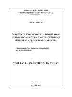
Calculation example
Calculation of arrangement of
stirrups for SFRC beams cross
section T. Load HL93 is
specified according to standard
TCVN11823-2017
*The size of the beam is as
shown in the figure 4.5
Figure 4.5. Beam size
Calculation results
Calculation results of belt reinforcement for high strength concrete
bridge girders with concrete grade 70MPa. Using Dramix 3D 80/60 BG
fiber reinforcement as described in Table 4.1
Calculation results of belt reinforcement for high strength concrete
bridge girders with concrete grade 70MPa. Using Dramix 3D 65/35 BG
fiber is described in Table 4.2.
download by :
22
Table 4.2 Calculation results of reinforcement for reinforced
concrete beams when using short fibers
Conclusion Chapter 4
Chapter 4 has given the design sequence of the high-strength concrete
bridge girders using steel fiber reinforcement and traditional girders and
bearing the design load HL93 according to the standard TCVN118232017 [1].
- If the beam size is kept the same, using a very small amount of steel
fiber reinforcement (νf<1%) the number of reinforcement has been
greatly reduced. The spacing of the rebar is narrower, making it easier
to install the rebar and pour concrete.
- It is completely possible to reduce the size of the beam if the girder is
kept intact and a small amount of steel fiber reinforcement is used.
- Current road bridge girders use reinforced concrete or prestressed
normal. The spacing of the reinforcement is now designed to be quite
thick to bear the force, so it is possible to use more steel fiber
reinforcement to reduce the traditional reinforcement. At that time, it is
necessary to add the shear calculation model for SFRC beams in the
current bridge design standards.
download by :
23
CONCLUSIONS AND RECOMMENDATIONS
Conclusion
1. . Analyzed and evaluated the methods of predicting the shear resistance
of reinforced concrete beams in general and in particular in the world and
in Vietnam;
2. The thesis has analyzed and selected the proposed Simple Modified
Compression Field (SMCFT) model to use to calculate the shear
resistance for HS SFRC beams.
3. From the analysis of the SMCFT model, it is shown that the main
contribution of the steel fiber reinforcement to the shear resistance is the
post-cracking tensile strength of the SFRC (σf).
4. The thesis has studied the influence of parameters on tensile strength and
tensile strength after cracking of HS SFRC such as fiber content,
compressive strength, fiber shape ratio...from the study. It can be seen
that the tensile strength after cracking depends greatly on the fiber
content, especially the reinforced concrete.
5. Experimental study on splicing 105 samples of HS SFRC with 7 grades
of reinforced concrete with steel content varying from 0% to 1.5% for
two fibers of different lengths. From the test results of the material
samples of 7 grades designed by the topic, the data was processed
statistically with the objective function being the splitting strength fsp, the
variable being the fiber reinforcement content (0%, 0.5%, 0.63). %,
1%,1.5%). Other input parameters are considered fixed (compressive
strength fc', fiber shape ratio Lf/Df,...), using short and long fibers,
concrete grade f’C=70MPa.
6. The thesis has built a linear regression function of the relationship
between the split strength and the fiber content for the reinforced concrete
structure. Since then, a model for calculating tensile strength after
cracking of steel fiber reinforcement has been proposed:
l
f 0.37 f f f 'c
df
7. Combining a simple modified compression field model, the thesis can
produce a model to predict the shear resistance of HS SFRC beam for
two cases a/d ≥ 2.5 and a/d < 2.5 as the method program (2 85) and (2
86). The formula for predicting the shear resistance of reinforced
concrete beams of HS SFRC for 2 cases is as
Lf
V ( f ' 0.37
f ' cot f cot )b d ,for a/d ≥ 2. 5;
n
c
f
Df
c
z
szcr
v
v
download by :