Tài liệu PERRY''''S CHEMICAL ENGINEERS HANDBOOK - 2 doc
Bạn đang xem bản rút gọn của tài liệu. Xem và tải ngay bản đầy đủ của tài liệu tại đây (36.7 MB, 1,045 trang )
Copyright © 2008, 1997, 1984, 1973, 1963, 1950, 1941, 1934 by The McGraw-Hill Companies, Inc. All rights reserved. Manufactured in the United
States of America. Except as permitted under the United States Copyright Act of 1976, no part of this publication may be reproduced or distributed
in any form or by any means, or stored in a database or retrieval system, without the prior written permission of the publisher.
0-07-154222-1
The material in this eBook also appears in the print version of this title: 0-07-151138-5.
All trademarks are trademarks of their respective owners. Rather than put a trademark symbol after every occurrence of a trademarked name, we use
names in an editorial fashion only, and to the benefit of the trademark owner, with no intention of infringement of the trademark. Where such
designations appear in this book, they have been printed with initial caps.
McGraw-Hill eBooks are available at special quantity discounts to use as premiums and sales promotions, or for use in corporate training programs.
For more information, please contact George Hoare, Special Sales, at or (212) 904-4069.
TERMS OF USE
This is a copyrighted work and The McGraw-Hill Companies, Inc. (“McGraw-Hill”) and its licensors reserve all rights in and to the work. Use of this
work is subject to these terms. Except as permitted under the Copyright Act of 1976 and the right to store and retrieve one copy of the work, you may
not decompile, disassemble, reverse engineer, reproduce, modify, create derivative works based upon, transmit, distribute, disseminate, sell, publish
or sublicense the work or any part of it without McGraw-Hill’s prior consent. You may use the work for your own noncommercial and personal use;
any other use of the work is strictly prohibited. Your right to use the work may be terminated if you fail to comply with these terms.
THE WORK IS PROVIDED “AS IS.” McGRAW-HILL AND ITS LICENSORS MAKE NO GUARANTEES OR WARRANTIES AS TO THE
ACCURACY, ADEQUACY OR COMPLETENESS OF OR RESULTS TO BE OBTAINED FROM USING THE WORK, INCLUDING ANY
INFORMATION THAT CAN BE ACCESSED THROUGH THE WORK VIA HYPERLINK OR OTHERWISE, AND EXPRESSLY DISCLAIM
ANY WARRANTY, EXPRESS OR IMPLIED, INCLUDING BUT NOT LIMITED TO IMPLIED WARRANTIES OF MERCHANTABILITY OR
FITNESS FOR A PARTICULAR PURPOSE. McGraw-Hill and its licensors do not warrant or guarantee that the functions contained in the work will
meet your requirements or that its operation will be uninterrupted or error free. Neither McGraw-Hill nor its licensors shall be liable to you or
anyone else for any inaccuracy, error or omission, regardless of cause, in the work or for any damages resulting therefrom. McGraw-Hill has no
responsibility for the content of any information accessed through the work. Under no circumstances shall McGraw-Hill and/or its licensors be liable
for any indirect, incidental, special, punitive, consequential or similar damages that result from the use of or inability to use the work, even if any of
them has been advised of the possibility of such damages. This limitation of liability shall apply to any claim or cause whatsoever whether such claim
or cause arises in contract, tort or otherwise.
DOI: 10.1036/0071511385
This page intentionally left blank
15-1
Section 15
Liquid-Liquid Extraction and Other
Liquid-Liquid Operations and Equipment*
Timothy C. Frank, Ph.D. Research Scientist and Sr. Technical Leader, The Dow Chemi-
cal Company; Member, American Institute of Chemical Engineers (Section Editor, Introduction
and Overview, Thermodynamic Basis for Liquid-Liquid Extraction, Solvent Screening Methods,
Liquid-Liquid Dispersion Fundamentals, Process Fundamentals and Basic Calculation Meth-
ods, Dual-Solvent Fractional Extraction, Extractor Selection, Packed Columns, Agitated Extrac-
tion Columns, Mixer-Settler Equipment, Centrifugal Extractors, Process Control Considerations,
Liquid-Liquid Phase Separation Equipment, Emerging Developments)
Lise Dahuron, Ph.D. Sr. Research Specialist, The Dow Chemical Company (Liquid Den-
sity, Viscosity, and Interfacial Tension; Liquid-Liquid Dispersion Fundamentals; Liquid-Liquid
Phase Separation Equipment; Membrane-Based Processes)
Bruce S. Holden, M.S. Process Research Leader, The Dow Chemical Company; Member,
American Institute of Chemical Engineers [Process Fundamentals and Basic Calculation Meth-
ods, Calculation Procedures, Computer-Aided Calculations (Simulations), Single-Solvent Frac-
tional Extraction with Extract Reflux, Liquid-Liquid Phase Separation Equipment]
William D. Prince, M.S. Process Engineering Associate, The Dow Chemical Company;
Member, American Institute of Chemical Engineers (Extractor Selection, Agitated Extraction
Columns, Mixer-Settler Equipment)
A. Frank Seibert, Ph.D., P.E. Technical Manager, Separations Research Program, The
University of Texas at Austin; Member, American Institute of Chemical Engineers (Liquid-
Liquid Dispersion Fundamentals, Process Fundamentals and Basic Calculation Methods,
Hydrodynamics of Column Extractors, Static Extraction Columns, Process Control Considera-
tions, Membrane-Based Processes)
Loren C. Wilson, B.S. Sr. Research Specialist, The Dow Chemical Company (Liquid Den-
sity, Viscosity, and Interfacial Tension; Phase Diagrams; Liquid-Liquid Equilibrium Experi-
mental Methods; Data Correlation Equations; Table of Selected Partition Ratio Data)
*Certain portions of this section are drawn from the work of Lanny A. Robbins and Roger W. Cusack, authors of Sec. 15 in the 7th edition. The input from numer-
ous expert reviewers also is gratefully acknowledged.
INTRODUCTION AND OVERVIEW
Historical Perspective. . . . . . . . . . . . . . . . . . . . . . . . . . . . . . . . . . . . . . 15-6
Uses for Liquid-Liquid Extraction. . . . . . . . . . . . . . . . . . . . . . . . . . . . . . . . 15-7
Definitions . . . . . . . . . . . . . . . . . . . . . . . . . . . . . . . . . . . . . . . . . . . . . . . . 15-10
Desirable Solvent Properties . . . . . . . . . . . . . . . . . . . . . . . . . . . . . . . . . . 15-11
Commercial Process Schemes . . . . . . . . . . . . . . . . . . . . . . . . . . . . . . . . . 15-13
Standard Extraction . . . . . . . . . . . . . . . . . . . . . . . . . . . . . . . . . . . . . . . 15-13
Fractional Extraction . . . . . . . . . . . . . . . . . . . . . . . . . . . . . . . . . . . . . . 15-13
Copyright © 2008, 1997, 1984, 1973, 1963, 1950, 1941, 1934 by The McGraw-Hill Companies, Inc. Click here for terms of use.
Dissociative Extraction. . . . . . . . . . . . . . . . . . . . . . . . . . . . . . . . . . . . . 15-15
pH-Swing Extraction . . . . . . . . . . . . . . . . . . . . . . . . . . . . . . . . . . . . . . 15-16
Reaction-Enhanced Extraction . . . . . . . . . . . . . . . . . . . . . . . . . . . . . . 15-16
Extractive Reaction. . . . . . . . . . . . . . . . . . . . . . . . . . . . . . . . . . . . . . . . 15-16
Temperature-Swing Extraction . . . . . . . . . . . . . . . . . . . . . . . . . . . . . . 15-17
Reversed Micellar Extraction. . . . . . . . . . . . . . . . . . . . . . . . . . . . . . . . 15-18
Aqueous Two-Phase Extraction . . . . . . . . . . . . . . . . . . . . . . . . . . . . . . 15-18
Hybrid Extraction Processes . . . . . . . . . . . . . . . . . . . . . . . . . . . . . . . . 15-18
Liquid-Solid Extraction (Leaching) . . . . . . . . . . . . . . . . . . . . . . . . . . . 15-19
Liquid-Liquid Partitioning of Fine Solids . . . . . . . . . . . . . . . . . . . . . . 15-19
Supercritical Fluid Extraction . . . . . . . . . . . . . . . . . . . . . . . . . . . . . . . 15-19
Key Considerations in the Design of an Extraction Operation . . . . . . . 15-20
Laboratory Practices. . . . . . . . . . . . . . . . . . . . . . . . . . . . . . . . . . . . . . . . . 15-21
THERMODYNAMIC BASIS FOR LIQUID-LIQUID EXTRACTION
Activity Coefficients and the Partition Ratio. . . . . . . . . . . . . . . . . . . . . . 15-22
Extraction Factor . . . . . . . . . . . . . . . . . . . . . . . . . . . . . . . . . . . . . . . . . 15-22
Separation Factor . . . . . . . . . . . . . . . . . . . . . . . . . . . . . . . . . . . . . . . . . 15-23
Minimum and Maximum Solvent-to-Feed Ratios. . . . . . . . . . . . . . . . 15-23
Temperature Effect . . . . . . . . . . . . . . . . . . . . . . . . . . . . . . . . . . . . . . . 15-23
Salting-out and Salting-in Effects for Nonionic Solutes . . . . . . . . . . . 15-24
Effect of pH for Ionizable Organic Solutes. . . . . . . . . . . . . . . . . . . . . 15-24
Phase Diagrams . . . . . . . . . . . . . . . . . . . . . . . . . . . . . . . . . . . . . . . . . . . . 15-25
Liquid-Liquid Equilibrium Experimental Methods . . . . . . . . . . . . . . . . 15-27
Data Correlation Equations . . . . . . . . . . . . . . . . . . . . . . . . . . . . . . . . . . . 15-27
Tie Line Correlations . . . . . . . . . . . . . . . . . . . . . . . . . . . . . . . . . . . . . . 15-27
Thermodynamic Models. . . . . . . . . . . . . . . . . . . . . . . . . . . . . . . . . . . . 15-28
Data Quality . . . . . . . . . . . . . . . . . . . . . . . . . . . . . . . . . . . . . . . . . . . . . 15-28
Table of Selected Partition Ratio Data . . . . . . . . . . . . . . . . . . . . . . . . . . 15-32
Phase Equilibrium Data Sources. . . . . . . . . . . . . . . . . . . . . . . . . . . . . . . 15-32
Recommended Model Systems . . . . . . . . . . . . . . . . . . . . . . . . . . . . . . . . 15-32
SOLVENT SCREENING METHODS
Use of Activity Coefficients and Related Data . . . . . . . . . . . . . . . . . . . . 15-32
Robbins’ Chart of Solute-Solvent Interactions . . . . . . . . . . . . . . . . . . . . 15-32
Activity Coefficient Prediction Methods . . . . . . . . . . . . . . . . . . . . . . . . . 15-33
Methods Used to Assess Liquid-Liquid Miscibility . . . . . . . . . . . . . . . . 15-34
Computer-Aided Molecular Design . . . . . . . . . . . . . . . . . . . . . . . . . . . . 15-38
High-Throughput Experimental Methods . . . . . . . . . . . . . . . . . . . . . . . 15-39
LIQUID DENSITY, VISCOSITY, AND INTERFACIAL TENSION
Density and Viscosity . . . . . . . . . . . . . . . . . . . . . . . . . . . . . . . . . . . . . . . . 15-39
Interfacial Tension . . . . . . . . . . . . . . . . . . . . . . . . . . . . . . . . . . . . . . . . . . 15-39
LIQUID-LIQUID DISPERSION FUNDAMENTALS
Holdup, Sauter Mean Diameter, and Interfacial Area . . . . . . . . . . . . . . 15-41
Factors Affecting Which Phase Is Dispersed . . . . . . . . . . . . . . . . . . . . . 15-41
Size of Dispersed Drops. . . . . . . . . . . . . . . . . . . . . . . . . . . . . . . . . . . . . . 15-42
Stability of Liquid-Liquid Dispersions . . . . . . . . . . . . . . . . . . . . . . . . . . 15-43
Effect of Solid-Surface Wettability . . . . . . . . . . . . . . . . . . . . . . . . . . . . . 15-43
Marangoni Instabilities. . . . . . . . . . . . . . . . . . . . . . . . . . . . . . . . . . . . . . . 15-43
PROCESS FUNDAMENTALS AND
BASIC CALCULATION METHODS
Theoretical (Equilibrium) Stage Calculations. . . . . . . . . . . . . . . . . . . . . 15-44
McCabe-Thiele Type of Graphical Method . . . . . . . . . . . . . . . . . . . . 15-45
Kremser-Souders-Brown Theoretical Stage Equation . . . . . . . . . . . . 15-45
Stage Efficiency . . . . . . . . . . . . . . . . . . . . . . . . . . . . . . . . . . . . . . . . . . 15-46
Rate-Based Calculations. . . . . . . . . . . . . . . . . . . . . . . . . . . . . . . . . . . . . . 15-47
Solute Diffusion and Mass-Transfer Coefficients . . . . . . . . . . . . . . . . 15-47
Mass-Transfer Rate and Overall Mass-Transfer Coefficients . . . . . . . 15-47
Mass-Transfer Units . . . . . . . . . . . . . . . . . . . . . . . . . . . . . . . . . . . . . . . 15-48
Extraction Factor and General Performance Trends . . . . . . . . . . . . . . . 15-49
Potential for Solute Purification Using Standard Extraction . . . . . . . . . 15-50
CALCULATION PROCEDURES
Shortcut Calculations . . . . . . . . . . . . . . . . . . . . . . . . . . . . . . . . . . . . . . . . 15-51
Example 1: Shortcut Calculation, Case A . . . . . . . . . . . . . . . . . . . . . . 15-52
Example 2: Shortcut Calculation, Case B . . . . . . . . . . . . . . . . . . . . . . 15-52
Example 3: Number of Transfer Units . . . . . . . . . . . . . . . . . . . . . . . . 15-53
Computer-Aided Calculations (Simulations). . . . . . . . . . . . . . . . . . . . . . 15-53
Example 4: Extraction of Phenol from Wastewater . . . . . . . . . . . . . . 15-54
Fractional Extraction Calculations. . . . . . . . . . . . . . . . . . . . . . . . . . . . . . 15-55
Dual-Solvent Fractional Extraction . . . . . . . . . . . . . . . . . . . . . . . . . . . 15-55
Single-Solvent Fractional Extraction with Extract Reflux . . . . . . . . . 15-56
Example 5: Simplified Sulfolane Process—Extraction
of Toluene from n-Heptane . . . . . . . . . . . . . . . . . . . . . . . . . . . . . . . . 15-56
LIQUID-LIQUID EXTRACTION EQUIPMENT
Extractor Selection . . . . . . . . . . . . . . . . . . . . . . . . . . . . . . . . . . . . . . . . . . 15-58
Hydrodynamics of Column Extractors . . . . . . . . . . . . . . . . . . . . . . . . . . 15-59
Flooding Phenomena . . . . . . . . . . . . . . . . . . . . . . . . . . . . . . . . . . . . . . 15-59
Accounting for Axial Mixing. . . . . . . . . . . . . . . . . . . . . . . . . . . . . . . . . 15-60
Liquid Distributors and Dispersers . . . . . . . . . . . . . . . . . . . . . . . . . . . 15-63
Static Extraction Columns . . . . . . . . . . . . . . . . . . . . . . . . . . . . . . . . . . . . 15-63
Common Features and Design Concepts . . . . . . . . . . . . . . . . . . . . . . 15-63
Spray Columns . . . . . . . . . . . . . . . . . . . . . . . . . . . . . . . . . . . . . . . . . . . 15-69
Packed Columns . . . . . . . . . . . . . . . . . . . . . . . . . . . . . . . . . . . . . . . . . . 15-70
Sieve Tray Columns . . . . . . . . . . . . . . . . . . . . . . . . . . . . . . . . . . . . . . . 15-74
Baffle Tray Columns. . . . . . . . . . . . . . . . . . . . . . . . . . . . . . . . . . . . . . . 15-78
Agitated Extraction Columns. . . . . . . . . . . . . . . . . . . . . . . . . . . . . . . . . . 15-79
Rotating-Impeller Columns . . . . . . . . . . . . . . . . . . . . . . . . . . . . . . . . . 15-79
Reciprocating-Plate Columns . . . . . . . . . . . . . . . . . . . . . . . . . . . . . . . 15-83
Rotating-Disk Contactor . . . . . . . . . . . . . . . . . . . . . . . . . . . . . . . . . . . 15-84
Pulsed-Liquid Columns . . . . . . . . . . . . . . . . . . . . . . . . . . . . . . . . . . . . 15-85
Raining-Bucket Contactor (a Horizontal Column) . . . . . . . . . . . . . . . 15-85
Mixer-Settler Equipment . . . . . . . . . . . . . . . . . . . . . . . . . . . . . . . . . . . . . 15-86
Mass-Transfer Models . . . . . . . . . . . . . . . . . . . . . . . . . . . . . . . . . . . . . 15-86
Miniplant Tests . . . . . . . . . . . . . . . . . . . . . . . . . . . . . . . . . . . . . . . . . . . 15-87
Liquid-Liquid Mixer Design . . . . . . . . . . . . . . . . . . . . . . . . . . . . . . . . 15-87
Scale-up Criteria. . . . . . . . . . . . . . . . . . . . . . . . . . . . . . . . . . . . . . . . . . 15-88
Specialized Mixer-Settler Equipment . . . . . . . . . . . . . . . . . . . . . . . . . 15-89
Suspended-Fiber Contactor. . . . . . . . . . . . . . . . . . . . . . . . . . . . . . . . . 15-90
Centrifugal Extractors . . . . . . . . . . . . . . . . . . . . . . . . . . . . . . . . . . . . . . . 15-91
Single-Stage Centrifugal Extractors. . . . . . . . . . . . . . . . . . . . . . . . . . . 15-91
Centrifugal Extractors Designed for
Multistage Performance . . . . . . . . . . . . . . . . . . . . . . . . . . . . . . . . . . . 15-92
PROCESS CONTROL CONSIDERATIONS
Steady-State Process Control. . . . . . . . . . . . . . . . . . . . . . . . . . . . . . . . . . 15-93
Sieve Tray Column Interface Control . . . . . . . . . . . . . . . . . . . . . . . . . . . 15-94
Controlled-Cycling Mode of Operation. . . . . . . . . . . . . . . . . . . . . . . . . . 15-94
LIQUID-LIQUID PHASE SEPARATION EQUIPMENT
Overall Process Considerations . . . . . . . . . . . . . . . . . . . . . . . . . . . . . . . . 15-96
Feed Characteristics. . . . . . . . . . . . . . . . . . . . . . . . . . . . . . . . . . . . . . . . . 15-96
Gravity Decanters (Settlers). . . . . . . . . . . . . . . . . . . . . . . . . . . . . . . . . . . 15-97
Design Considerations . . . . . . . . . . . . . . . . . . . . . . . . . . . . . . . . . . . . . 15-97
Vented Decanters . . . . . . . . . . . . . . . . . . . . . . . . . . . . . . . . . . . . . . . . . 15-98
Decanters with Coalescing Internals . . . . . . . . . . . . . . . . . . . . . . . . . . 15-99
Sizing Methods . . . . . . . . . . . . . . . . . . . . . . . . . . . . . . . . . . . . . . . . . . . 15-99
Other Types of Separators . . . . . . . . . . . . . . . . . . . . . . . . . . . . . . . . . . . . 15-101
Coalescers . . . . . . . . . . . . . . . . . . . . . . . . . . . . . . . . . . . . . . . . . . . . . . . 15-101
Centrifuges . . . . . . . . . . . . . . . . . . . . . . . . . . . . . . . . . . . . . . . . . . . . . . 15-101
Hydrocyclones . . . . . . . . . . . . . . . . . . . . . . . . . . . . . . . . . . . . . . . . . . . 15-101
Ultrafiltration Membranes . . . . . . . . . . . . . . . . . . . . . . . . . . . . . . . . . . 15-102
Electrotreaters . . . . . . . . . . . . . . . . . . . . . . . . . . . . . . . . . . . . . . . . . . . 15-102
EMERGING DEVELOPMENTS
Membrane-Based Processes . . . . . . . . . . . . . . . . . . . . . . . . . . . . . . . . . . 15-103
Polymer Membranes . . . . . . . . . . . . . . . . . . . . . . . . . . . . . . . . . . . . . . 15-103
Liquid Membranes . . . . . . . . . . . . . . . . . . . . . . . . . . . . . . . . . . . . . . . . 15-104
Electrically Enhanced Extraction . . . . . . . . . . . . . . . . . . . . . . . . . . . . . . 15-104
Phase Transition Extraction and Tunable Solvents . . . . . . . . . . . . . . . . . 15-105
Ionic Liquids. . . . . . . . . . . . . . . . . . . . . . . . . . . . . . . . . . . . . . . . . . . . . . . 15-105
15-2 LIQUID-LIQUID EXTRACTION AND OTHER LIQUID-LIQUID OPERATIONS AND EQUIPMENT
LIQUID-LIQUID EXTRACTION AND OTHER LIQUID-LIQUID OPERATIONS AND EQUIPMENT 15-3
a Interfacial area per unit m
2
/m
3
ft
2
/ft
3
volume
a
p
Specific packing surface area m
2
/m
3
ft
2
/ft
3
(area per unit volume)
a
w
Specific wall surface area m
2
/m
3
ft
2
/ft
3
(area per unit volume)
b
ij
NRTL model regression K K
parameter (see Table 15-10)
A Envelope-style downcomer m
2
ft
2
area
A Area between settled layers m
2
ft
2
in a decanter
A
col
Column cross-sectional area m
2
ft
2
A
dow
Area for flow through m
2
ft
2
a downcorner (or
upcomer)
A
i,j
/RT van Laar binary interaction Dimensionless Dimensionless
parameter
A
o
Cross-sectional area of a m
2
in
2
single hole
C Concentration (mass or kgրm
3
or lb/ft
3
or
mol per unit volume) kgmolրm
3
lbmolրft
3
or gmolրL
C
A
i
Concentration of component kgրm
3
or lb/ft
3
or
A at the interface kgmolրm
3
lbmolրft
3
or gmolրL
C* Concentration at equilibrium kgրm
3
or lb/ft
3
or
kgmolրm
3
lbmolրft
3
or gmolրL
C
D
Drag coefficient Dimensionless Dimensionless
C
o
Initial concentration kgրm
3
or lb/ft
3
kgmolրm
3
or lbmolրft
3
or gmolրL
C
t
Concentration at time t kgրm
3
or lb/ft
3
kgmolրm
3
or lbmolրft
3
or gmolրL
d Drop diameter m in
d
C
Critical packing dimension m in
d
i
Diameter of an individual drop m in
d
m
Characteristic diameter of m in
media in a packed bed
d
o
Orifice or nozzle diameter m in
d
p
Sauter mean drop diameter m in
d
32
Sauter mean drop diameter m in
D
col
Column diameter m in or ft
D
eq
Equivalent diameter giving m in
the same area
D
h
Equivalent hydraulic diameter m in
D
i
Distribution ratio for a given
chemical species including
all its forms (unspecified units)
D
i
Impeller diameter or m in or ft
characteristic mixer
diameter
D
sm
Static mixer diameter m in or ft
D
t
Tank diameter m ft
D Molecular diffusion coefficient m
2
/s cm
2
/s
(diffusivity)
D
AB
Mutual diffusion coefficient m
2
/s cm
2
/s
for components A and B
E Mass or mass flow rate of kg or kg/s lb or lb/h
extract phase
E′ Solvent mass or mass flow rate
(in the extract phase)
E Axial mixing coefficient m
2
/s cm
2
/s
(eddy diffusivity)
E
C
Extraction factor for case C Dimensionless Dimensionless
[Eq. (15-98)]
E
i
Extraction factor for Dimensionless Dimensionless
component i
E
s
Stripping section extraction Dimensionless Dimensionless
factor
E
w
Washing section extraction Dimensionless Dimensionless
factor
f
da
Fractional downcomer area Dimensionless Dimensionless
in Eq. (15-160)
f
ha
Fractional hole area in Dimensionless Dimensionless
Eq. (15-159)
F Mass or mass flow rate of kg or kg/s lb or lb/h
feed phase
F Force N lb
f
F′ Feed mass or mass flow rate kg or kg/s lb or lb/h
(feed solvent only)
F
R
Solute reduction factor (ratio of Dimensionless Dimensionless
inlet to outlet concentrations)
g Gravitational acceleration 9.807 m/s
2
32.17 ft/s
2
G
ij
NRTL model parameter Dimensionless Dimensionless
h Height of coalesced layer at m in
a sieve tray
h Head loss due to frictional flow m in
h Height of dispersion band in m in
batch decanter
h
i
E
Excess enthalpy Jրgmol Btuրlbmol
of mixing or calրgmol
H Dimensionless group defined Dimensionless Dimensionless
by Eq. (15-123)
H Dimension of envelope-style m in or ft
downcomer (Fig. 15-39)
∆H Steady-state dispersion band m in
height in a continuously fed
decanter
HDU Height of a dispersion unit m in
H
e
Height of a transfer unit due m in
to resistance in extract phase
HETS Height equivalent to a m in
theoretical stage
H
or
Height of an overall m in
mass-tranfer unit based on
raffinate phase
H
r
Height of a transfer unit due m in
to resistance in raffinate phase
I Ionic strength in Eq. (15-26)
k Individual mass-transfer m/s or cm/s ft/h
coefficient
k Mass-transfer coefficient
(unspecified units)
k
m
Membrane-side mass-transfer m/s or cm/s ft/h
coefficient
k
o
Overall mass-transfer m/s or cm/s ft/h
coefficient
k
c
Continuous-phase m/s or cm/s ft/h
mass-transfer coefficient
k
d
Dispersed-phase mass-transfer m/s or cm/s ft/h
coefficient
k
s
Setschenow constant Lրgmol Lրgmol
k
s
Shell-side mass-transfer m/s or cm/s ft/h
coefficient
k
t
Tube-side mass-transfer m/s or cm/s ft/h
coefficient
K Partition ratio (unspecified units)
K′
s
Stripping section partition Mass ratio/ Mass ratio/
ratio (in Bancroft coordinates) mass ratio mass ratio
Nomenclature
A given symbol may represent more than one property. The appropriate meaning should be apparent from the context. The equations given in Sec. 15 reflect the
use of the SI or cgs system of units and not ft-lb-s units, unless otherwise noted in the text. The gravitational conversion factor g
c
needed to use ft-lb-s units is not
included in the equations.
U.S. Customary U.S. Customary
Symbol Definition SI units System units Symbol Definition SI units System units
15-4 LIQUID-LIQUID EXTRACTION AND OTHER LIQUID-LIQUID OPERATIONS AND EQUIPMENT
Re Reynolds number: for pipe Dimensionless Dimensionless
flow, Vdρրµ; for an impeller,
ρ
m
ωD
i
2
րµ
m
; for drops, V
so
d
p
ρ
c
ր
µ
c
; for flow in a packed-bed
coalescer, Vd
m
ρ
c
րµ; for flow
through an orifice, V
o
d
o
ρ
d
րµ
d
Re
Stokes
ρ
c
∆ρgd
3
p
ր18µ
c
2
Dimensionless Dimensionless
S Mass or mass flow rate of kg or kg/s lb or lb/h
solvent phase
S Dimension of envelope-style m ft
downcomer (Fig. 15-39)
S′ Solvent mass or mass flow kg or kg/s lb or lb/h
rate (extraction solvent only)
S′
s
Mass flow rate of extraction kg/s lb/h
solvent within stripping
section
S′
w
Mass flow rate of extraction kg/s lb/h
solvent within washing section
S
i,j
Separation power for Dimensionless Dimensionless
separating component i from
component j [defined by
Eq. (15-105)]
S
tip
Impeller tip speed m/s ft/s
t
b
Batch mixing time s or h min or h
T Temperature (absolute) K °R
u
t
Stokes’ law terminal or m/s or cm/s ft/s or ft/min
settling velocity of a drop
u
t∞
Unhindered settling velocity m/s or cm/s ft/s or ft/min
of a single drop
v Molar volume m
3
րkgmol or ft
3
րlbmol
cm
3
րgmol
V Liquid velocity (or m/s ft/s or ft/min
volumetric flow per
unit area)
V Volume m
3
ft
3
or gal
V
cf
Continuous-phase m/s ft/s or ft/min
flooding velocity
V
cflow
Cross-flow velocity of m/s ft/s or ft/min
continuous phase at
sieve tray
V
df
Dispersed-phase m/s ft/s or ft/min
flooding velocity
V
drop
Average velocity of a m/s ft/s or ft/min
dispersed drop
V
ic
Interstitial velocity of m/s ft/s or ft/min
continuous phase
V
o,max
Maximum velocity through m/s ft/s or ft/min
an orifice or nozzle
V
s
Slip velocity m/s ft/s or ft/min
V
so
Slip velocity at low m/s ft/s or ft/min
dispersed-phase flow rate
V
sm
Static mixer superficial liquid m/s ft/s or ft/min
velocity (entrance velocity)
W Mass or mass flow rate of kg or kg/s lb or lb/h
wash solvent phase
W′
s
Mass flow rate of wash solvent kg/s lb/h
within stripping section
W′
w
Mass flow rate of wash solvent kg/s lb/h
within washing section
We Weber number: for an Dimensionless Dimensionless
impeller, ρ
c
ω
2
D
i
3
րσ; for flow
through an orifice or nozzle,
V
o
2
d
o
ρ
d
րσ; for a static mixer,
V
2
sm
D
sm
ρ
c
րσ
x Mole fraction solute in feed Mole fraction Mole fraction
or raffinate
X Concentration of solute in feed
or raffinate (unspecified units)
X″ Mass fraction solute in feed Mass fractions Mass fractions
or raffinate
X′ Mass solute/mass feed Mass ratios Mass ratios
solvent in feed or raffinate
X
f
B
Pseudoconcentration of Mass ratios Mass ratios
solute in feed for case B
[Eq. (15-95)]
K′
w
Washing section partition ratio Mass ratio/ Mass ratio/
(in Bancroft coordinates) mass ratio mass ratio
K′ Partition ratio, mass ratio basis Mass ratio/ Mass ratio/
(Bancroft coordinates) mass ratio mass ratio
K″ Partition ratio, mass fraction Mass fraction/ Mass fraction/
basis mass fraction mass fraction
K
o
Partition ratio, mole Mole fraction/ Mole fraction/
fraction basis mole fraction mole fraction
K
vol
Partition ratio (volumetric Ratio of kg/m
3
Ratio of lb/ft
3
concentration basis) or kgmolրm
3
or lbmolրft
3
or gmolրL
L Downcomer (or m in or ft
upcomer) length
L
fp
Length of flow path in m in or ft
Eq. (15-161)
m Local slope of equilibrium line
(unspecified concentration
units)
m′ Local slope of equilibrium line Mass ratio/ Mass ratio/
(in Bancroft coordinates) mass ratio mass ratio
m
dc
Local slope of equilibrium line
for dispersed-phase
concentration plotted versus
continuous-phase
concentration
m
er
Local slope of equilibrium
line for extract-phase
concentration plotted
versus raffinate-phase
concentration
m
vol
Local slope of equilibrium Ratio of kg/m
3
Ratio of lb/ft
3
or
line (volumetric or kgmolրm
3
lbmolրft
3
concentration basis) or gmolրL units
M Mass or mass flow rate kg or kg/s lb or lb/h
MW Molecular weight kgրkgmol or lbրlbmol
gրgmol
N Number of theoretical stages Dimensionless Dimensionless
N
A
Flux of component A (mass (kg or kgmol)/ (lb or lbmol)ր
or mol/area/unit time) (m
2
⋅s) (ft
2
⋅s)
N
holes
Number of holes Dimensionless Dimensionless
N
or
Number of overall Dimensionless Dimensionless
mass-transfer units based
on the raffinate phase
N
s
Number of theoretical stages Dimensionless Dimensionless
in stripping section
N
w
Number of theoretical stages Dimensionless Dimensionless
in washing section
P Pressure bar or Pa atm or lb
f
/in
2
P Dimensionless group defined Dimensionless Dimensionless
by Eq. (15-122)
P Power W or kW HP or ft⋅lb
f
/h
Pe Péclet number Vb/E, Dimensionless Dimensionless
where V is liquid
velocity, E is axial mixing
coefficient, and b is a
characteristic equipment
dimension
P
i,extract
Purity of solute i in wt % wt %
extract (in wt %)
P
i,feed
Purity of solute i in feed wt % wt %
(in wt %)
P
o
Power number Pր(ρ
m
ω
3
D
i
5
) Dimensionless Dimensionless
∆P
dow
Pressure drop for flow bar or Pa atm or lb
f
/in
2
through a downcomer
(or upcomer)
∆P
o
Orifice pressure drop bar or Pa atm or lb
f
/in
2
q MOSCED induction Dimensionless Dimensionless
parameter
Q Volumetric flow rate m
3
/s ft
3
/min
R Universal gas constant 8.31 J⋅Kր 1.99 Btu⋅°Rր
kgmol lbmol
R Mass or mass flow rate of kg or kg/s lb or lb/h
raffinate phase
R
A
Rate of mass-transfer (moles kgmolրs lbmolրh
per unit time)
Nomenclature (Continued)
U.S. Customary U.S. Customary
Symbol Definition SI units System units Symbol Definition SI units System units
LIQUID-LIQUID EXTRACTION AND OTHER LIQUID-LIQUID OPERATIONS AND EQUIPMENT 15-5
Nomenclature (Concluded)
U.S. Customary U.S. Customary
Symbol Definition SI units System units Symbol Definition SI units System units
X
f
C
Pseudoconcentration of Mass ratios Mass ratios
solute in feed for case C
[Eq. (15-97)]
X
i,extract
Concentration of solute i Mass fraction Mass fraction
in extract
X
i,feed
Concentration of solute i Mass fraction Mass fraction
in feed
X
ij
Concentration of component Mass fraction Mass fraction
i in the phase richest in j
y Mole fraction solute in Mole fraction Mole fraction
solvent or extract
Y Concentration of solute in
the solvent or extract
(unspecified units)
Y″ Mass fraction solute Mass fraction Mass fraction
in solvent or extract
Y′ Mass solute/mass extraction Mass ratio Mass ratio
solvent in solvent or
extract
Y
s
B
Pseudoconcentration of Mass ratio Mass ratio
solute in solvent for case B
[Eq. (15-96)]
z Dimension or direction of m in or ft
mass transfer
z Sieve tray spacing m in or ft
z Point representing feed
composition on a tie line
z
i
Number of electronic Dimensionless Dimensionless
charges on an ion
Z
t
Total height of extractor m ft
Greek Symbols
α MOSCED hydrogen-bond (J/cm
3
)
1/2
(cal/cm
3
)
1/2
acidity parameter
α Solvatochromic hydrogen-bond (J/cm
3
)
1/2
(cal/cm
3
)
1/2
acidity parameter
α
i,j
Separation factor for solute i Dimensionless Dimensionless
with respect to solute j
α
i,j
NRTL model parameter Dimensionless Dimensionless
β MOSCED hydrogen-bond (J/cm
3
)
1/2
(cal/cm
3
)
1/2
basicity parameter
β Solvatochromic hydrogen-bond (J/cm
3
)
1/2
(cal/cm
3
)
1/2
basicity parameter
γ
i,j
Activity coefficient of i Dimensionless Dimensionless
dissolved in j
γ
∞
Activity coefficient at Dimensionless Dimensionless
infinite dilution
γ
C
i
Activity coefficient, Dimensionless Dimensionless
combinatorial part of
UNIFAC
γ
i
I
Activity coefficient of Dimensionless Dimensionless
component i in phase I
γ
i
R
Activity coefficient, residual Dimensionless Dimensionless
part of UNIFAC
ε Void fraction Dimensionless Dimensionless
ε Fractional open area of a Dimensionless Dimensionless
perforated plate
δ Solvatochromic polarizability (J/cm
3
)
1/2
(cal/cm
3
)
1/2
parameter
δ
d
Hansen nonpolar (dispersion) (J/cm
3
)
1/2
(cal/cm
3
)
1/2
solubility parameter
δ
h
Hansen solubility parameter (J/cm
3
)
1/2
(cal/cm
3
)
1/2
for hydrogen bonding
δ
p
Hansen polar solubility (J/cm
3
)
1/2
(cal/cm
3
)
1/2
parameter
Greek Symbols
δ
i
Solubility parameter for (J/cm
3
)
1/2
(cal/cm
3
)
1/2
component i
δ
⎯
Solubility parameter for mixture (J/cm
3
)
1/2
(cal/cm
3
)
1/2
ζ Tortuosity factor defined by Dimensionless Dimensionless
Eq. (15-147)
θ Residence time for total liquid s s or min
θ
i
Fraction of solute i extracted Dimensionless Dimensionless
from feed
λ MOSCED dispersion parameter (J/cm
3
)
1/2
(cal/cm
3
)
1/2
λ
m
Membrane thickness mm in
µ Liquid viscosity Pa⋅scP
µ
i
I
Chemical potential of J/gmol Btu/lbmol
component i in phase I
µ
m
Mixture mean viscosity Pa⋅scP
defined in Eq. (15-180)
µ
w
Reference viscosity (of water) Pa⋅scP
ξ
1
MOSCED asymmetry factor Dimensionless Dimensionless
ξ
batch
Efficiency of a batch Dimensionless Dimensionless
experiment [Eq. (15-175)]
ξ
continuous
Efficiency of a continuous Dimensionless Dimensionless
process [Eq. (15-176)]
ξ
m
Murphree stage efficiency Dimensionless Dimensionless
ξ
md
Murphree stage efficiency Dimensionless Dimensionless
based on dispersed phase
ξ
o
Overall stage efficiency Dimensionless Dimensionless
π Solvatochromic polarity (J/cm
3
)
1/2
(cal/cm
3
)
1/2
parameter
∆π Osmotic pressure gradient bar or Pa atm or lb
f
/in
2
ρ Liquid density kg/m
3
lb/ft
3
ρ
m
Mixture mean density defined kg/m
3
lb/ft
3
in Eq. (15-178)
σ Interfacial tension N/m dyn/cm
τ MOSCED polarity parameter (J/cm
3
)
1/2
(cal/cm
3
)
1/2
τ
i,j
NRTL model parameter Dimensionless Dimensionless
φ Volume fraction Dimensionless Dimensionless
φ
d
Volume fraction of dispersed Dimensionless Dimensionless
phase (holdup)
φ
d,feed
Volume fraction of dispersed Dimensionless Dimensionless
phase in feed
φ
o
Initial dispersed-phase holdup Dimensionless Dimensionless
in feed to a decanter
ϕ Volume fraction of voids Dimensionless Dimensionless
in a packed bed
Φ Factor governing use of Eqs. Dimensionless Dimensionless
(15-148) and (15-149)
χ Parameter in Eq. (15-41) Dimensionless Dimensionless
indicating which phase is
likely to be dispersed
ω Impeller speed Rotations/s Rotations/min
Additional Subscripts
c Continuous phase
d Dispersed phase
e Extract phase
f Feed phase or flooding condition (when combined with d or c)
i Component i
j Component j
H Heavy liquid
L Light liquid
max Maximum value
min Minimum value
o Orifice or nozzle
r Raffinate phase
s Solvent
GENERAL REFERENCES: Wankat, Separation Process Engineering, 2d ed.
(Prentice-Hall, 2006); Seader and Henley, Separation Process Principles, 2d ed.
(Wiley, 2006); Seibert, “Extraction and Leaching,” Chap. 14 in Chemical Process
Equipment: Selection and Design, 2d ed., Couper et al., eds. (Elsevier, 2005);
Aguilar and Cortina, Solvent Extraction and Liquid Membranes: Fundamentals
and Applications in New Materials (Dekker, 2005); Glatz and Parker, “Enriching
Liquid-Liquid Extraction,” Chem. Eng. Magazine, 111(11), pp. 44–48 (2004); Sol-
vent Extraction Principles and Practice, 2d ed., Rydberg et al., eds. (Dekker, 2004);
Ion Exchange and Solvent Extraction, vol. 17, Marcus and SenGupta, eds. (Dekker,
2004), and earlier volumes in the series; Leng and Calabrese, “Immiscible Liquid-
Liquid Systems,” Chap. 12 in Handbook of Industrial Mixing: Science and Practice,
Paul, Atiemo-Obeng, and Kresta, eds. (Wiley, 2004); Cheremisinoff, Industrial Sol-
vents Handbook, 2d ed. (Dekker, 2003); Van Brunt and Kanel, “Extraction with
Reaction,” Chap. 3 in Reactive Separation Processes, Kulprathipanja, ed. (Taylor &
Francis, 2002); Mueller et al., “Liquid-Liquid Extraction” in Ullmann’s Encyclope-
dia of Industrial Chemistry, 6th ed. (VCH, 2002); Benitez, Principles and Modern
Applications of Mass Transfer Operations (Wiley, 2002); Wypych, Handbook of Sol-
vents (Chemtec, 2001); Flick, Industrial Solvents Handbook, 5th ed. (Noyes,
1998); Robbins, “Liquid-Liquid Extraction,” Sec. 1.9 in Handbook of Separation
Techniques for Chemical Engineers, 3d ed., Schweitzer, ed. (McGraw-Hill, 1997);
Lo, “Commercial Liquid-Liquid Extraction Equipment,” Sec. 1.10 in Handbook of
Separation Techniques for Chemical Engineers, 3d ed., Schweitzer, ed. (McGraw-
Hill, 1997); Humphrey and Keller, “Extraction,” Chap. 3 in Separation Process
Technology (McGraw-Hill, 1997), pp. 113–151; Cusack and Glatz, “Apply Liquid-
Liquid Extraction to Today’s Problems,” Chem. Eng. Magazine, 103(7), pp. 94–103
(1996); Liquid-Liquid Extraction Equipment, Godfrey and Slater, eds. (Wiley,
1994); Zaslavsky, Aqueous Two-Phase Partitioning (Dekker, 1994); Strigle, “Liquid-
Liquid Extraction,” Chap. 11 in Packed Tower Design and Applications, 2d ed.
(Gulf, 1994); Schügerl, Solvent Extraction in Biotechnology (Springer-Verlag,
1994); Schügerl, “Liquid-Liquid Extraction (Small Molecules),” Chap. 21 in
Biotechnology, 2d ed., vol. 3, Stephanopoulos, ed. (VCH, 1993); Kelley and Hat-
ton, “Protein Purification by Liquid-Liquid Extraction,” Chap. 22 in Biotechnol-
ogy, 2d ed., vol. 3, Stephanopoulos, ed. (VCH, 1993); Lo and Baird, “Extraction,
Liquid-Liquid,” in Kirk-Othmer Encyclopedia of Chemical Technology, 4th ed.,
vol. 10, Kroschwitz and Howe-Grant, eds. (Wiley, 1993), pp. 125–180; Science and
Practice of Liquid-Liquid Extraction, vol. 1, Phase Equilibria; Mass Transfer and
Interfacial Phenomena; Extractor Hydrodynamics, Selection, and Design, and vol.
2, Process Chemistry and Extraction Operations in the Hydrometallurgical,
Nuclear, Pharmaceutical, and Food Industries, Thornton, ed. (Oxford, 1992);
Cusack, Fremeaux, and Glatz, “A Fresh Look at Liquid-Liquid Extraction,” pt. 1,
“Extraction Systems,” Chem. Eng. Magazine, 98(2), pp. 66–67 (1991); Cusack and
Fremeauz, pt. 2, “Inside the Extractor,” Chem. Eng. Magazine, 98(3), pp. 132–138
(1991); Cusack and Karr, pt. 3, “Extractor Design and Specification,” Chem. Eng.
Magazine, 98(4), pp. 112–120 (1991); Methods in Enzymology, vol. 182, Guide to
Protein Purification, Deutscher, ed. (Academic, 1990); Wankat, Equilibrium
Staged Separations (Prentice Hall, 1988); Blumberg, Liquid-Liquid Extraction
(Academic, 1988); Skelland and Tedder, “Extraction—Organic Chemicals Process-
ing,” Chap. 7 in Handbook of Separation Process Technology, Rousseau, ed. (Wiley,
1987); Chapman, “Extraction—Metals Processing,” Chap. 8 in Handbook of Sepa-
ration Process Technology, Rousseau, ed. (Wiley, 1987); Novak, Matous, and Pick,
Liquid-Liquid Equilibria, Studies in Modern Thermodynamics Series, vol. 7 (Else-
vier, 1987); Bailes et al., “Extraction, Liquid-Liquid” in Encyclopedia of Chemical
Processing and Design, vol. 21, McKetta and Cunningham, eds. (Dekker, 1984),
pp. 19–166; Handbook of Solvent Extraction, Lo, Baird, and Hanson, eds. (Wiley,
1983; Krieger, 1991); Sorenson and Arlt, Liquid-Liquid Equilibrium Data Collec-
tion, DECHEMA, Binary Systems, vol. V, pt. 1, 1979, Ternary Systems, vol. V, pt.
2, 1980, Ternary and Quaternary Systems, vol. 5, pt. 3, 1980, Macedo and Ras-
mussen, Suppl. 1, vol. V, pt. 4, 1987; Wisniak and Tamir, Liquid-Liquid Equilibrium
and Extraction, a Literature Source Book, vols. I and II (Elsevier, 1980–1981),
Suppl. 1 (1985); Treybal, Mass Transfer Operations, 3d ed. (McGraw-Hill, 1980);
King, Separation Processes, 2d ed. (McGraw-Hill, 1980); Laddha and Degaleesan,
Transport Phenomena in Liquid Extraction (McGraw-Hill, 1978); Brian, Staged
Cascades in Chemical Processing (Prentice-Hall, 1972); Pratt, Countercurrent Sep-
aration Processes (Elsevier, 1967); Treybal, “Liquid Extractor Performance,”
Chem. Eng. Prog., 62(9), pp. 67–75 (1966); Treybal, Liquid Extraction,2ded.
(McGraw-Hill, 1963); Alders, Liquid-Liquid Extraction, 2d ed. (Elsevier, 1959).
INTRODUCTION AND OVERVIEW
Liquid-liquid extraction is a process for separating the components of
a liquid (the feed) by contact with a second liquid phase (the solvent).
The process takes advantage of differences in the chemical proper-
ties of the feed components, such as differences in polarity and
hydrophobic/hydrophilic character, to separate them. Stated more
precisely, the transfer of components from one phase to the other is
driven by a deviation from thermodynamic equilibrium, and the
equilibrium state depends on the nature of the interactions between
the feed components and the solvent phase. The potential for sepa-
rating the feed components is determined by differences in these
interactions.
A liquid-liquid extraction process produces a solvent-rich stream
called the extract that contains a portion of the feed and an extracted-
feed stream called the raffinate. A commercial process almost always
includes two or more auxiliary operations in addition to the extraction
operation itself. These extra operations are needed to treat the extract
and raffinate streams for the purposes of isolating a desired product,
recovering the solvent for recycle to the extractor, and purging
unwanted components from the process. A typical process includes
two or more distillation operations in addition to extraction.
Liquid-liquid extraction is used to recover desired components
from a crude liquid mixture or to remove unwanted contaminants. In
developing a process, the project team must decide what solvent or
solvent mixture to use, how to recover solvent from the extract, and
how to remove solvent residues from the raffinate. The team must
also decide what temperature or range of temperatures should be
used for the extraction, what process scheme to employ among many
possibilities, and what type of equipment to use for liquid-liquid con-
tacting and phase separation. The variety of commercial equipment
options is large and includes stirred tanks and decanters, specialized
mixer-settlers, a wide variety of agitated and nonagitated extraction
columns or towers, and various types of centrifuges.
Because of the availability of hundreds of commercial solvents and
extractants, as well as a wide variety of established process schemes
and equipment options, liquid-liquid extraction is a versatile technol-
ogy with a wide range of commercial applications. It is utilized in the
processing of numerous commodity and specialty chemicals including
metals and nuclear fuel (hydrometallurgy), petrochemicals, coal and
wood-derived chemicals, and complex organics such as pharmaceuti-
cals and agricultural chemicals. Liquid-liquid extraction also is an
important operation in industrial wastewater treatment, food process-
ing, and the recovery of biomolecules from fermentation broth.
HISTORICAL PERSPECTIVE
The art of solvent extraction has been practiced in one form or
another since ancient times. It appears that prior to the 19th century
solvent extraction was primarily used to isolate desired components
such as perfumes and dyes from plant solids and other natural sources
[Aftalion, A History of the International Chemical Industry (Univ.
Penn. Press, 1991); and Taylor, A History of Industrial Chemistry
(Abelard-Schuman, 1957)]. However, several early applications
involving liquid-liquid contacting are described by Blass, Liebel, and
Haeberl [“Solvent Extraction—A Historical Review,” International
Solvent Extraction Conf. (ISEC) ‘96 Proceedings (Univ. of Mel-
bourne, 1996)], including the removal of pigment from oil by using
water as the solvent.
The modern practice of liquid-liquid extraction has its roots in the
middle to late 19th century when extraction became an important lab-
oratory technique. The partition ratio concept describing how a solute
partitions between two liquid phases at equilibrium was introduced by
Berthelot and Jungfleisch [Ann. Chim. Phys., 4, p. 26 (1872)] and fur-
ther defined by Nernst [Z. Phys. Chemie, 8, p. 110 (1891)]. At about
the same time, Gibbs published his theory of phase equilibrium (1876
and 1878). These and other advances were accompanied by a growing
chemical industry. An early countercurrent extraction process utiliz-
ing ethyl acetate solvent was patented by Goering in 1883 as a method
for recovering acetic acid from “pyroligneous acid” produced by
pyrolysis of wood [Othmer, p. xiv in Handbook of Solvent Extraction
(Wiley, 1983; Krieger, 1991)], and Pfleiderer patented a stirred extrac-
tion column in 1898 [Blass, Liebl, and Haeberl, ISEC ’96 Proceedings
(Univ. of Melbourne, 1996)].
15-6
With the emergence of the chemical engineering profession in the
1890s and early 20th century, additional attention was given to process
fundamentals and development of a more quantitative basis for
process design. Many of the advances made in the study of distillation
and absorption were readily adapted to liquid-liquid extraction, owing
to its similarity as another diffusion-based operation. Examples
include application of mass-transfer coefficients [Lewis, Ind. Eng.
Chem., 8(9), pp. 825–833 (1916); and Lewis and Whitman, Ind. Eng.
Chem., 16(12), pp. 1215–1220 (1924)], the use of graphical stagewise
design methods [McCabe and Thiele, Ind. Eng. Chem., 17(6), pp.
605–611 (1925); Evans, Ind. Eng. Chem., 26(8), pp. 860–864 (1934);
and Thiele, Ind. Eng. Chem., 27(4), pp. 392–396 (1935)], the use of
theoretical-stage calculations [Kremser, National Petroleum News,
22(21), pp. 43–49 (1930); and Souders and Brown, Ind. Eng. Chem.
24(5), pp. 519–522 (1932)], and the transfer unit concept introduced
in the late 1930s by Colburn and others [Colburn, Ind. Eng. Chem.,
33(4), pp. 459–467 (1941)]. Additional background is given by
Hampe, Hartland, and Slater [Chap. 2 in Liquid-Liquid Extraction
Equipment, Godfrey and Slater, eds. (Wiley, 1994)].
The number of commercial applications continued to grow, and by
the 1930s liquid-liquid extraction had replaced various chemical treat-
ment methods for refining mineral oil and coal tar products [Varter-
essian and Fenske, Ind. Eng. Chem., 28(8), pp. 928–933 (1936)]. It
was also used to recover acetic acid from waste liquors generated in
the production of cellulose acetate, and in various nitration and sul-
fonation processes [Hunter and Nash, The Industrial Chemist,
9(102–104), pp. 245–248, 263–266, 313–316 (1933)]. The article by
Hunter and Nash also describes early mixer-settler equipment, mixing
jets, and various extraction columns including the spray column, baf-
fle tray column, sieve tray column, and a packed column filled with
Raschig rings or coke breeze, the material left behind when coke is
burned.
Much of the liquid-liquid extraction technology in practice today
was first introduced to industry during a period of vigorous innovation
and growth of the chemical industry as a whole from about 1920 to
1970. The advances of this period include development of fractional
extraction schemes including work described by Cornish et al., [Ind.
Eng. Chem., 26(4), pp. 397–406 (1934)] and by Thiele [Ind. Eng.
Chem., 27(4), pp. 392–396 (1935)]. A well-known commercial exam-
ple involving the use of extract reflux is the Udex process for separat-
ing aromatic compounds from hydrocarbon mixtures using diethylene
glycol, a process developed jointly by The Dow Chemical Company
and Universal Oil Products in the 1940s. This period also saw the
introduction of many new equipment designs including specialized
mixer-settler equipment, mechanically agitated extraction columns,
and centrifugal extractors as well as a great increase in the availability
of different types of industrial solvents. A variety of alcohols, ketones,
esters, and chlorinated hydrocarbons became available in large quan-
tities beginning in the 1930s, as petroleum refiners and chemical
companies found ways to manufacture them inexpensively using the
byproducts of petroleum refining operations or natural gas. Later, a
number of specialty solvents were introduced including sulfolane
(tetrahydrothiophene-1,1-dioxane) and NMP (N-methyl-2-pyrrolidi-
none) for improved extraction of aromatics from hydrocarbons.
Specialized extractants also were developed including numerous
organophosphorous extractants used to recover or purify metals dis-
solved in aqueous solutions.
The ready availability of numerous solvents and extractants, com-
bined with the tremendous growth of the chemical industry, drove the
development and implementation of many new industrial applica-
tions. Handbooks of chemical process technology provide a glimpse of
some of these [Riegel’s Handbook of Industrial Chemistry, 10th ed.,
Kent, ed. (Springer, 2003); Chemical Processing Handbook, McKetta,
ed. (Dekker, 1993); and Austin, Shreve’s Chemical Process Industries,
5th ed. (McGraw-Hill, 1984)], but many remain proprietary and are
not widely known. The better-known examples include the separation
of aromatics from aliphatics, as mentioned above, extraction of phe-
nolic compounds from coal tars and liquors, recovery of ε-caprolactam
for production of polyamide-6 (nylon-6), recovery of hydrogen perox-
ide from oxidized anthraquinone solution, plus many processes involv-
ing the washing of crude organic streams with alkaline or acidic
solutions and water, and the detoxification of industrial wastewater
prior to biotreatment using steam-strippable organic solvents. The
pharmaceutical and specialty chemicals industry also began using liq-
uid-liquid extraction in the production of new synthetic drug com-
pounds and other complex organics. In these processes, often
involving multiple batch reaction steps, liquid-liquid extraction gener-
ally is used for recovery of intermediates or crude products prior to
final isolation of a pure product by crystallization. In the inorganic
chemical industry, extraction processes were developed for purifica-
tion of phosphoric acid, purification of copper by removal of arsenic
impurities, and recovery of uranium from phosphate-rock leach solu-
tions, among other applications. Extraction processes also were devel-
oped for bioprocessing applications, including the recovery of citric
acid from broth using trialkylamine extractants, the use of amyl
acetate to recover antibiotics from fermentation broth, and the use of
water-soluble polymers in aqueous two-phase extraction for purifica-
tion of proteins.
The use of supercritical or near-supercritical fluids for extraction, a
subject area normally set apart from discussions of liquid-liquid
extraction, has received a great deal of attention in the R&D commu-
nity since the 1970s. Some processes were developed many years
before then; e.g., the propane deasphalting process used to refine
lubricating oils uses propane at near-supercritical conditions, and this
technology dates back to the 1930s [McHugh and Krukonis, Super-
critical Fluid Processing, 2d ed. (Butterworth-Heinemann, 1993)]. In
more recent years the use of supercritical fluids has found a number
of commercial applications displacing earlier liquid-liquid extraction
methods, particularly for recovery of high-value products meant for
human consumption including decaffeinated coffee, flavor compo-
nents from citrus oils, and vitamins from natural sources.
Significant progress continues to be made toward improving extrac-
tion technology, including the introduction of new methods to esti-
mate solvent properties and screen candidate solvents and solvent
blends, new methods for overall process conceptualization and opti-
mization, and new methods for equipment design. Progress also is
being made by applying the technology developed for a particular
application in one industry to improve another application in another
industry. For example, much can be learned by comparing equipment
and practices used in organic chemical production with those used in
the inorganic chemical industry (and vice versa), or by comparing
practices used in commodity chemical processing with those used in
the specialty chemicals industry. And new concepts offering potential
for significant improvements continue to be described in the litera-
ture. (See “Emerging Developments.”)
USES FOR LIQUID-LIQUID EXTRACTION
For many separation applications, the use of liquid-liquid extraction is
an alternative to the various distillation schemes described in Sec. 13,
“Distillation.” In many of these cases, a distillation process is more eco-
nomical largely because the extraction process requires extra opera-
tions to process the extract and raffinate streams, and these operations
usually involve the use of distillation anyway. However, in certain cases
the use of liquid-liquid extraction is more cost-effective than using dis-
tillation alone because it can be implemented with smaller equipment
and/or lower energy consumption. In these cases, differences in chem-
ical or molecular interactions between feed components and the sol-
vent provide a more effective means of accomplishing the desired
separation compared to differences in component volatilities.
For example, liquid-liquid extraction may be preferred when the
relative volatility of key components is less than 1.3 or so, such that an
unusually tall distillation tower is required or the design involves high
reflux ratios and high energy consumption. In certain cases, the distil-
lation option may involve addition of a solvent (extractive distillation)
or an entrainer (azeotropic distillation) to enhance the relative volatil-
ity. Even in these cases, a liquid-liquid extraction process may offer
advantages in terms of higher selectivity or lower solvent usage and
lower energy consumption, depending upon the application. Extrac-
tion may be preferred when the distillation option requires operation
at pressures less than about 70 mbar (about 50 mmHg) and an unusu-
ally large-diameter distillation tower is required, or when most of the
INTRODUCTION AND OVERVIEW 15-7
feed must be taken overhead to isolate a desired bottoms product.
Extraction may also be attractive when distillation requires use of
high-pressure steam for the reboiler or refrigeration for overheads
condensation [Null, Chem. Eng. Prog., 76(8), pp. 42–49 (August
1980)], or when the desired product is temperature-sensitive and
extraction can provide a gentler separation process.
Of course, liquid-liquid extraction also may be a useful option when
the components of interest simply cannot be separated by using distil-
lation methods. An example is the use of liquid-liquid extraction
employing a steam-strippable solvent to remove nonstrippable, low-
volatility contaminants from wastewater [Robbins, Chem. Eng. Prog.,
76(10), pp. 58–61 (1980)]. The same process scheme often provides a
cost-effective alternative to direct distillation or stripping of volatile
impurities when the relative volatility of the impurity with respect to
water is less than about 10 [Robbins, U.S. Patent 4,236,973 (1980);
Hwang, Keller, and Olson, Ind. Eng. Chem. Res., 31, pp. 1753–1759
(1992); and Frank et al., Ind. Eng. Chem. Res., 46(11), pp. 3774–3786
(2007)].
Liquid-liquid extraction also can be an attractive alternative to sepa-
ration methods, other than distillation, e.g., as an alternative to crystal-
lization from solution to remove dissolved salts from a crude organic
feed, since extraction of the salt content into water eliminates the need
to filter solids from the mother liquor, often a difficult or expensive
operation. Extraction also may compete with process-scale chromatog-
raphy, an example being the recovery of hydroxytyrosol (3,4-dihydroxy-
phenylethanol), an antioxidant food additive, from olive-processing
wastewaters [Guzman et al., U.S. Patent 6,849,770 (2005)].
The attractiveness of liquid-liquid extraction for a given application
compared to alternative separation technologies often depends upon
the concentration of solute in the feed. The recovery of acetic acid
from aqueous solutions is a well-known example [Brown, Chem. Eng.
Prog., 59(10), pp. 65–68 (1963)]. In this case, extraction generally is
more economical than distillation when handling dilute to moderately
concentrated feeds, while distillation is more economical at higher
concentrations. In the treatment of water to remove trace amounts of
organics, when the concentration of impurities in the feed is greater
than about 20 to 50 ppm, liquid-liquid extraction may be more eco-
nomical than adsorption of the impurities by using carbon beds,
because the latter may require frequent and costly replacement of the
adsorbent [Robbins, Chem. Eng. Prog., 76(10), pp. 58–61 (1980)]. At
lower concentrations of impurities, adsorption may be the more eco-
nomical option because the usable lifetime of the carbon bed is
longer.
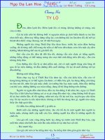
Examples of cost-effective liquid-liquid extraction processes utiliz-
ing relatively low-boiling solvents include the recovery of acetic acid
from aqueous solutions using ethyl ether or ethyl acetate [King, Chap.
18.5 in Handbook of Solvent Extraction, Lo, Baird, and Hanson, eds.
(Wiley, 1983, Krieger, 1991)] and the recovery of phenolic compounds
from water by using methyl isobutyl ketone [Greminger et al., Ind.
Eng. Chem. Process Des. Dev., 21(1), pp. 51–54 (1982)]. In these
processes, the solvent is recovered from the extract by distillation, and
dissolved solvent is removed from the raffinate by steam stripping
(Fig. 15-1). The solvent circulates through the process in a closed
loop.
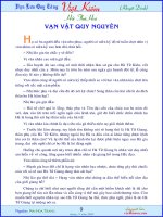
One of the largest applications of liquid-liquid extraction in terms
of total worldwide production volume involves the extraction of aro-
matic compounds from hydrocarbon mixtures in petrochemical oper-
ations using high-boiling polar solvents. A number of processes have
been developed to recover benzene, toluene, and xylene (BTX) as
feedstock for chemical manufacturing or to refine motor oils. This
general technology is described in detail in “Single-Solvent Fractional
Extraction with Extract Reflux” under “Calculation Procedures.” A
typical flow diagram is shown in Fig. 15-2. Liquid-liquid extraction
also may be used to upgrade used motor oil; an extraction process
employing a relatively light polar solvent such as N,N-dimethylform-
amide or acetonitrile has been developed to remove polynuclear aro-
matic and sulfur-containing contaminants [Sherman, Hershberger,
and Taylor, U.S. Patent 6,320,090 (2001)]. An alternative process uti-
lizes a blend of methyl ethyl ketone + 2-propanol and small amounts
of aqueous KOH [Rincón, Cañizares, and García, Ind. Eng. Chem.
Res., 44(20), pp. 7854–7859 (2005)].
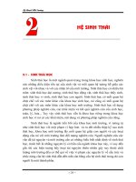
Extraction also is used to remove CO
2
, H
2
S, and other acidic contam-
inants from liquefied petroleum gases (LPGs) generated during opera-
tion of fluid catalytic crackers and cokers in petroleum refineries, and
from liquefied natural gas (LNG). The acid gases are extracted from the
liquefied hydrocarbons (primarily C
1
to C
3
) by reversible reaction with
various amine extractants. Typical amines are methyldiethanolamine
(MDEA), diethanolamine (DEA), and monoethanolamine (MEA). In a
typical process (Fig. 15-3), the treated hydrocarbon liquid (the raffi-
nate) is washed with water to remove residual amine, and the loaded
amine solution (the extract) is regenerated in a stripping tower for recy-
cle back to the extractor [Nielsen et al., Hydrocarbon Proc., 76, pp.
49–59 (1997)]. The technology is similar to that used to scrub CO
2
and
H
2
S from gas streams [Oyenekan and Rochelle, Ind. Eng. Chem. Res.,
45(8), pp. 2465–2472 (2006); and Jassim and Rochelle, Ind. Eng. Chem.
Res., 45(8), pp. 2457–2464 (2006)], except that the process involves liq-
uid-liquid contacting instead of gas-liquid contacting. Because of this, a
common stripper often is used to regenerate solvent from a variety of
gas absorbers and liquid-liquid extractors operated within a typical
refinery. In certain applications, organic acids such as formic acid are
present in low concentrations in the hydrocarbon feed. These contami-
nants will react with the amine extractant to form heat-stable amine
salts that accumulate in the solvent loop over time, requiring periodic
purging or regeneration of the solvent solution [Price and Burns,
Hydrocarbon Proc., 74, pp. 140–141 (1995)]. The amine-based extrac-
tion process is an alternative to washing with caustic or the use of solid
adsorbents.
A typical extraction process used in hydrometallurgical applications
is outlined in Fig. 15-4. This technology involves transferring the
desired element from the ore leachate liquor, an aqueous acid, into an
organic solvent phase containing specialty extractants that form a
complex with the metal ion. The organic phase is later contacted with
an aqueous solution at a different pH and temperature to regenerate
the solvent and transfer the metal into a clean solution from which it
can be recovered by electrolysis or another method [Cox, Chap. 1 in
Science and Practice of Liquid-Liquid Extraction, vol. 2, Thornton,
ed. (Oxford, 1992)]. Another process technology utilizes metals com-
plexed with various organophosphorus compounds as recyclable
homogeneous catalysts; liquid-liquid extraction is used to transfer the
metal complex between the reaction phase and a separate liquid phase
after reaction. Different ligands having different polarities are chosen
to facilitate the use of various extraction and recycle schemes [Kanel
et al., U.S. Patents 6,294,700 (2001) and 6,303,829 (2001)].
Another category of useful liquid-liquid extraction applications
involves the recovery of antibiotics and other complex organics from
fermentation broth by using a variety of oxygenated organic solvents
such as acetates and ketones. Although some of these products are
unstable at the required extraction conditions (particularly if pH must
15-8 LIQUID-LIQUID EXTRACTION AND OTHER LIQUID-LIQUID OPERATIONS AND EQUIPMENT
FIG. 15-1 Typical process for extraction of acetic acid from water.
INTRODUCTION AND OVERVIEW 15-9
Extract
Raffinate to Water
Wash Column
E
X
T
R
Solvent
Recovered
Solvent
Reflux
Reformate (Feed)
S
T
R
I
P
P
E
R
Product
D
I
S
T
Simulated
Process
(Example 5)
FIG. 15-2 Flow sheet of a simplified aromatic extraction process (see Example 5).
Extract
Raffinate
E
X
T
R
D
I
S
T
To Acid Gas
Disposal
Recycle Solvent
Sour
Feed
Washwater
To Amine Recovery or Disposal
Sweetened Hydrocarbon
FIG. 15-3 Typical process for extracting acid gases from LPG or LNG.
be low for favorable partitioning), short-contact-time centrifugal
extractors may be used to minimize exposure. Centrifugal extractors
also help overcome problems associated with formation of emulsions
between solvent and broth. In a number of applications, the whole
broth can be processed without prior removal of solids, a practice that
can significantly reduce costs. For detailed information, see “The His-
tory of Penicillin Production,” Elder, ed., Chemical Engineering
Progress Symposium Series No. 100, vol. 66, pp. 37–42 (1970); Queener
and Swartz, “Penicillins: Biosynthetic and Semisynthetic,” in Secondary
Products of Metabolism, Economic Microbiology, vol. 3, Rose, ed. (Aca-
demic, 1979); and Chaung et al., J. Chinese Inst. Chem. Eng., 20(3), pp.
155–161 (1989). Another well-known commercial application of liquid-
liquid extraction in bioprocessing is the Baniel process for the recovery
of citric acid from fermentation broth with tertiary amine extractants
[Baniel, Blumberg, and Hadju, U.S. Patent 4,275,234 (1980)]. This type
of process is discussed in “Reaction-Enhanced Extraction” under “Com-
mercial Process Schemes.”
DEFINITIONS
Extraction terms defined by the International Union of Pure and
Applied Chemistry (IUPAC) generally are recommended. [See Rice,
Irving, and Leonard, Pure Appl. Chem. (IUPAC), 65(11), pp.
2673–2396 (1993); and J. Inczédy, Pure Appl. Chem. (IUPAC), 66(12),
pp. 2501–2512 (1994).] Liquid-liquid extraction is a process for sep-
arating components dissolved in a liquid feed by contact with a second
liquid phase. Solvent extraction is a broader term that describes a
process for separating the components of any matrix by contact with a
liquid, and it includes liquid-solid extraction (leaching) as well as liquid-
liquid extraction. The feed to a liquid-liquid extraction process is the
solution that contains the components to be separated. The major liquid
component (or components) in the feed can be referred to as the feed
solvent or the carrier solvent. Minor components in solution often
are referred to as solutes. The extraction solvent is the immiscible or
partially miscible liquid added to the process to create a second liquid
phase for the purpose of extracting one or more solutes from the feed.
It is also called the separating agent and may be a mixture of several
individual solvents (a mixed solvent or a solvent blend). The extrac-
tion solvent also may be a liquid comprised of an extractant dissolved
in a liquid diluent. In this case, the extractant species is primarily
responsible for extraction of solute due to a relatively strong attractive
interaction with the desired solute, forming a reversible adduct or mol-
ecular complex. The diluent itself does not contribute significantly to
the extraction of solute and in this respect is not the same as a true
extraction solvent. A modifier may be added to the diluent to increase
the solubility of the extractant or otherwise enhance the effectiveness of
the extractant. The phase leaving a liquid-liquid contactor rich in extrac-
tion solvent is called the extract. The raffinate is the liquid phase left
from the feed after it is contacted by the extract phase. The word raffi-
nate originally referred to a “refined product”; however, common usage
has extended its meaning to describe the feed phase after extraction
whether that phase is a product or not.
Industrial liquid-liquid extraction most often involves processing
two immiscible or partially miscible liquids in the form of a disper-
sion of droplets of one liquid (the dispersed phase) suspended in
the other liquid (the continuous phase). The dispersion will exhibit
a distribution of drop diameters d
i
often characterized by the volume
to surface area average diameter or Sauter mean drop diameter.
The term emulsion generally refers to a liquid-liquid dispersion with
a dispersed-phase mean drop diameter on the order of 1 µm or less.
The tension that exists between two liquid phases is called the
interfacial tension. It is a measure of the energy or work required to
increase the surface area of the liquid-liquid interface, and it affects
the size of dispersed drops. Its value, in units of force per unit length
or energy per unit area, reflects the compatibility of the two liquids.
Systems that have low compatibility (low mutual solubility) exhibit
high interfacial tension. Such a system tends to form relatively large
dispersed drops and low interfacial area to minimize contact between
the phases. Systems that are more compatible (with higher mutual sol-
ubility) exhibit lower interfacial tension and more easily form small
dispersed droplets.
A theoretical or equilibrium stage is a device or combination of
devices that accomplishes the effect of intimately mixing two liquid
phases until equilibrium concentrations are reached, then physically
separating the two phases into clear layers. The partition ratio K is
commonly defined for a given solute as the solute concentration in the
extract phase divided by that in the raffinate phase after equilibrium is
attained in a single stage of contacting. A variety of concentration units
are used, so it is important to determine how partition ratios have been
defined in the literature for a given application. The term partition
ratio is preferred, but it also is referred to as the distribution con-
stant, distribution coefficient, or the K value. It is a measure of the
15-10 LIQUID-LIQUID EXTRACTION AND OTHER LIQUID-LIQUID OPERATIONS AND EQUIPMENT
Stripping (Back Extraction)
Solvent Extraction
Ore
Acid Leaching
Depleted
Leachate
Aqueous
Leachate
Lean
Organic
Loaded
Organic
Impurities
Aqueous
Scrub
Liquor
Impurity Removal
Winning
Depleted
Aqueous
Loaded
Aqueous
Metal
FIG. 15-4 Example process scheme used in hydrometallurgical applications. [Taken from Cox, Chap. 1 in
Science and Practice of Liquid-Liquid Extraction, vol. 2, Thornton, ed. (Oxford, 1992), with permission.
Copyright 1992 Oxford University Press.]
thermodynamic potential of a solvent for extracting a given solute and
can be a strong function of composition and temperature. In some
cases, the partition ratio transitions from a value less than unity to a
value greater than unity as a function of solute concentration. A system
of this type is called a solutrope [Smith, Ind. Eng. Chem., 42(6), pp.
1206–1209 (1950)]. The term distribution ratio, designated by D
i
, is
used in analytical chemistry to describe the distribution of a species
that undergoes chemical reaction or dissociation, in terms of the total
concentration of analyte in one phase over that in the other, regardless
of its chemical form.
The extraction factor E is a process variable that characterizes the
capacity of the extract phase to carry solute relative to the feed phase.
Its value largely determines the number of theoretical stages required
to transfer solute from the feed to the extract. The extraction factor is
analogous to the stripping factor in distillation and is the ratio of the
slope of the equilibrium line to the slope of the operating line in a
McCabe-Thiele type of stagewise graphical calculation. For a stan-
dard extraction process with straight equilibrium and operating lines,
E is constant and equal to the partition ratio for the solute of interest
times the ratio of the solvent flow rate to the feed flow rate. The sep-
aration factor a
i,j
measures the relative enrichment of solute i in
the extract phase, compared to solute j, after one theoretical stage
of extraction. It is equal to the ratio of K values for components i and j
and is used to characterize the selectivity a solvent has for a given
solute.
A standard extraction process is one in which the primary pur-
pose is to transfer solute from the feed phase into the extract phase in
a manner analogous to stripping in distillation. Fractional extraction
refers to a process in which two or more solutes present in the feed are
sharply separated from each other, one fraction leaving the extractor
in the extract and the other in the raffinate. Cross-current or cross-
flow extraction (Fig. 15-5) is a series of discrete stages in which the
raffinate R from one extraction stage is contacted with additional fresh
solvent S in a subsequent stage. Countercurrent extraction (Fig.
15-6) is an extraction scheme in which the extraction solvent enters
the stage or end of the extraction farthest from where the feed F
enters, and the two phases pass each other in countercurrent fashion.
The objective is to transfer one or more components from the feed
solution F into the extract E. Compared to cross-current operation,
countercurrent operation generally allows operation with less solvent.
When a staged contactor is used, the two phases are mixed with
droplets of one phase suspended in the other, but the phases are sep-
arated before leaving each stage. A countercurrent cascade is a
process utilizing multiple staged contactors with countercurrent flow
of solvent and feed streams from stage to stage. When a differential
contactor is used, one of the phases can remain dispersed as drops
throughout the contactor as the phases pass each other in countercur-
rent fashion. The dispersed phase is then allowed to coalesce at the
end of the device before being discharged. For these types of
processes, mass-transfer units (or the related mass-transfer coef-
ficients) often are used instead of theoretical stages to characterize
separation performance. For a given phase, mass-transfer units are
defined as the integral of the differential change in solute concentra-
tion divided by the deviation from equilibrium, between the limits of
inlet and outlet solute concentrations. A single transfer unit repre-
sents the change in solute concentration equal to that achieved by a
single theoretical stage when the extraction factor is equal to 1.0. It
differs from a theoretical stage at other values of the extraction factor.
The term flooding generally refers to excessive breakthrough or
entrainment of one liquid phase into the discharge stream of the other.
The flooding characteristics of an extractor limit its hydraulic capacity.
Flooding can be caused by excessive flow rates within the equipment,
by phase inversion due to accumulation and coalescence of dispersed
droplets, or by formation of stable dispersions or emulsions due to the
presence of surface-active impurities or excessive agitation. The flood
point typically refers to the specific total volumetric throughput in
(m
3
/h)/m
2
or gpm/ft
2
of cross-sectional area (or the equivalent phase
velocity in m/s or ft/s) at which flooding begins.
DESIRABLE SOLVENT PROPERTIES
Common industrial solvents generally are single-functionality organic
solvents such as ketones, esters, alcohols, linear or branched aliphatic
hydrocarbons, aromatic hydrocarbons, and so on; or water, which may
be acidic or basic or mixed with water-soluble organic solvents. More
complex solvents are sometimes used to obtain specific properties
needed for a given application. These include compounds with multi-
ple functional groups such as diols or triols, glycol ethers, and alkanol
amines as well as heterocyclic compounds such as pine-derived sol-
vents (terpenes), sulfolane (tetrahydrothiophene-1,1-dioxane), and
NMP (N-methyl-2-pyrrolidinone). Solvent properties have been sum-
marized in a number of handbooks and databases including those by
Cheremisinoff, Industrial Solvents Handbook, 2d ed. (Dekker, 2003);
Wypych, Handbook of Solvents (ChemTech, 2001); Wypych, Solvents
Database, CD-ROM (ChemTec, 2001); Yaws, Thermodynamic and
Physical Property Data, 2d ed. (Gulf, 1998); and Flick, Industrial Sol-
vents Handbook, 5th ed. (Noyes, 1998). Solvents are sometimes
blended to obtain specific properties, another approach to achieving a
multifunctional solvent with properties tailored for a given applica-
tion. Examples are discussed by Escudero, Cabezas, and Coca [Chem.
Eng. Comm., 173, pp. 135–146 (1999)] and by Delden et al. [Chem.
Eng. Technol., 29(10), pp. 1221–1226 (2006)]. As discussed earlier, a
solvent also may be a liquid containing a dissolved extractant species,
the extractant chosen because it forms a specific attractive interaction
with the desired solute.
In terms of desirable properties, no single solvent or solvent blend
can be best in every respect. The choice of solvent often is a compro-
mise, and the relative weighting given to the various considerations
depends on the given situation. Assessments should take into account
long-term sustainability and overall cost of ownership. Normally, the
factors considered in choosing a solvent include the following.
1. Loading capacity. This property refers to the maximum con-
centration of solute the extract phase can hold before two liquid
phases can no longer coexist or solute precipitates as a separate phase.
INTRODUCTION AND OVERVIEW 15-11
S
1
F
E
1
S
2
R
1
E
2
S
3
R
2
E
3
R
3
FIG. 15-5 Cross-current extraction.
S
F
E
1
or E
Feed Stage
R
1
E
2
Raffinate Stage
R
2
E
3
R or R
3
FIG. 15-6 Standard countercurrent extraction.
If a specialized extractant is used, loading capacity may be determined
by the point at which all the extractant in solution is completely occu-
pied by solute and extractant solubility limits capacity. If loading
capacity is low, a high solvent-to-feed ratio may be needed even if the
partition ratio is high.
2. Partition ratio K
i
= Y
i
/X
i
. Partition ratios on the order of K
i
= 10
or higher are desired for an economical process because they allow
operation with minimal amounts of solvent (more specifically, with a
minimal solvent-to-feed ratio) and production of higher solute con-
centrations in the extract—unless the solute concentration in the feed
already is high and a limitation in the solvent’s loading capacity deter-
mines the required solvent-to-feed ratio. Since high partition ratios
generally allow for low solvent use, smaller and less costly extraction
equipment may be used and costs for solvent recovery and recycle are
lower. In principle, partition ratios less than K
i
= 1.0 may be accom-
modated by using a high solvent-to-feed ratio, but usually at much
higher cost.
3. Solute selectivity. In certain applications, it is important not
only to recover a desired solute from the feed, but also to separate it
from other solutes present in the feed and thereby achieve a degree of
solute purification. The selectivity of a given solvent for solute i com-
pared to solute j is characterized by the separation factor α
i,j
= K
i
/K
j
.
Values must be greater than α
i,j
= 1.0 to achieve an increase in solute
purity (on a solvent-free basis). When solvent blends are used in a com-
mercial process, often it is because the blend provides higher selectiv-
ity, and often at the expense of a somewhat lower partition ratio. The
degree of purification that can be achieved also depends on the
extraction scheme chosen for the process, the amount of extraction
solvent, and the number of stages employed.
4. Mutual solubility. Low liquid-liquid mutual solubility between
feed and solvent phases is desirable because it reduces the separation
requirements for removing solvents from the extract and raffinate
streams. Low solubility of extraction solvent in the raffinate phase
often results in high relative volatility for stripping the residual solvent
in a raffinate stripper, allowing low-cost desolventizing of the raffinate
[Hwang, Keller, and Olson, Ind. Eng. Chem. Res., 31(7), pp.
1753–1759 (1992)]. Low solubility of feed solvent in the extract phase
reduces separation requirements for recovering solvent for recycle
and producing a purified product solute. In some cases, if the solubil-
ity of feed solvent in the extract is high, more than one distillation
operation will be required to separate the extract phase. If mutual sol-
ubility is nil (as for aliphatic hydrocarbons dissolved in water), the
need for stripping or another treatment method may be avoided as
long as efficient liquid-liquid phase separation can be accomplished
without entrainment of solvent droplets into the raffinate. However,
very low mutual solubility normally is achieved at the expense of a
lower partition ratio for extracting the desired solute—because a sol-
vent that has very little compatibility with the feed solvent is not likely
to be a good extractant for something that is dissolved in the feed sol-
vent—and therefore has some compatibility. Mutual solubility also
limits the solvent-to-feed ratios that can be used, since a point can be
reached where the solvent stream is so large it dissolves the entire
feed stream, or the solvent stream is so small it is dissolved by the
feed, and these can be real limitations for systems with high mutual
solubility.
5. Stability. The solvent should have little tendency to react with
the product solute and form unwanted by-products, causing a loss in
yield. Also it should not react with feed components or degrade to
undesirable contaminants that cause development of undesirable
odors or color over time, or cause difficulty achieving desired product
purity, or accumulate in the process because they are difficult to purge.
6. Density difference. As a general rule, a difference in density
between solvent and feed phases on the order of 0.1 to 0.3 g/mL is
preferred. A value that is too low makes for poor or slow liquid-liquid
phase separation and may require use of a centrifuge. A value that is
too high makes it difficult to build high dispersed-droplet population
density for good mass transfer; i.e., it is difficult to mix the two phases
together and maintain high holdup of the dispersed phase within the
extractor—but this depends on the viscosity of the continuous phase.
7. Viscosity. Low viscosity is preferred since higher viscosity
generally increases mass-transfer resistance and liquid-liquid phase
separation difficulty. Sometimes an extraction process is operated at
an elevated temperature where viscosity is significantly lower for bet-
ter mass-transfer performance, even when this results in a lower par-
tition ratio. Low viscosity at ambient temperatures also facilitates
transfer of solvent from storage to processing equipment.
8. Interfacial tension. Preferred values for interfacial tension
between the feed phase and the extraction solvent phase generally are
in the range of 5 to 25 dyn/cm (1 dyn/cm is equivalent to 10
−3
N/m).
Systems with lower values easily emulsify. For systems with higher
values, dispersed droplets tend to coalesce easily, resulting in low
interfacial area and poor mass-transfer performance unless mechani-
cal agitation is used.
9. Recoverability. The economical recovery of solvent from the
extract and raffinate is critical to commercial success. Solvent physical
properties should facilitate low-cost options for solvent recovery, recy-
cle, and storage. For example, the use of relatively low-boiling organic
solvents with low heats of vaporization generally allows cost-effective
use of distillation and stripping for solvent recovery. Solvent proper-
ties also should enable low-cost methods for purging impurities from
the overall process (lights and/or heavies) that may accumulate over
time. One of the challenges often encountered in utilizing a high-boil-
ing solvent or extractant involves accumulation of heavy impurities in
the solvent phase and difficulty in removing them from the process.
Another consideration is the ease with which solvent residues can be
reduced to low levels in final extract or raffinate products, particularly
for food-grade products and pharmaceuticals.
10. Freezing point. Solvents that are liquids at all anticipated
ambient temperatures are desirable since they avoid the need for
freeze protection and/or thawing of frozen solvent prior to use. Some-
times an “antifreeze” compound such as water or an aliphatic hydro-
carbon can be added to the solvent, or the solvent is supplied as a
mixture of related compounds instead of a single pure component—to
suppress the freezing point.
11. Safety. Solvents with low potential for fire and reactive chem-
istry hazards are preferred as inherently safe solvents. In all cases, sol-
vents must be used with a full awareness of potential hazards and in a
manner consistent with measures needed to avoid hazards. For infor-
mation on the safe use of solvents and their potential hazards, see Sec.
23, “Safety and Handling of Hazardous Materials.” Also see Crowl and
Louvar, Chemical Process Safety: Fundamentals with Applications
(Prentice-Hall, 2001); Yaws, Handbook of Chemical Compound Data
for Process Safety (Elsevier, 1997); Lees, Loss Prevention in the
Process Industries (Butterworth, 1996); and Bretherick’s Handbook of
Reactive Chemical Hazards, 6th ed., Urben and Pitt, eds. (Butter-
worth-Heinemann, 1999).
12. Industrial hygiene. Solvents with low mammalian toxicity and
good warning properties are desired. Low toxicity and low dermal
absorption rate reduce the potential for injury through acute expo-
sure. A thorough review of the medical literature must be conducted
to ascertain chronic toxicity issues. Measures needed to avoid unsafe
exposures must be incorporated into process designs and imple-
mented in operating procedures. See Goetsch, Occupational Safety
and Health for Technologists, Engineers, and Managers (Prentice-
Hall, 2004).
13. Environmental requirements. The solvent must have physi-
cal or chemical properties that allow effective control of emissions
from vents and other discharge streams. Preferred properties
include low aquatic toxicity and low potential for fugitive emissions
from leaks or spills. It also is desirable for a solvent to have low pho-
toreactivity in the atmosphere and be biodegradable so it does not
persist in the environment. Efficient technologies for capturing sol-
vent vapors from vents and condensing them for recycle include
activated carbon adsorption with steam regeneration [Smallwood,
Solvent Recovery Handbook (McGraw-Hill, 1993), pp. 7–14] and
vacuum-swing adsorption [Pezolt et al., Environmental Prog., 16(1),
pp. 16–19 (1997)]. The optimization of a process to increase the effi-
ciency of solvent utilization is a key aspect of waste minimization and
reduction of environmental impact. An opportunity may exist to
reduce solvent use through application of countercurrent processing
and other chemical engineering principles aimed at improving pro-
cessing efficiencies. For a discussion of environmental issues in
15-12 LIQUID-LIQUID EXTRACTION AND OTHER LIQUID-LIQUID OPERATIONS AND EQUIPMENT
process design, see Allen and Shonnard, Green Engineering: Envi-
ronmentally Conscious Design of Chemical Processes (Prentice-
Hall, 2002)]. Also see Sec. 22, “Waste Management.”
14. Multiple uses. It is desirable to use as the extraction solvent a
material that can serve a number of purposes in the manufacturing
plant. This avoids the cost of storing and handling multiple solvents. It
may be possible to use a single solvent for a number of different
extraction processes practiced in the same facility, either in different
equipment operated at the same time or by using the same equipment
in a series of product campaigns. In other cases, the solvent used for
extraction may be one of the raw materials for a reaction carried out in
the same facility, or a solvent used in another operation such as a crys-
tallization.
15. Materials of construction. It is desirable for a solvent to allow
the use of common, relatively inexpensive materials of construction at
moderate temperatures and pressures. Material compatability and
potential for corrosion are discussed in Sec. 25, “Materials of Con-
struction.”
16. Availability and cost. The solvent should be readily available
at a reasonable cost. Considerations include the initial fill cost, the
investment costs associated with maintaining a solvent inventory in
the plant (particularly when expensive extractants are used), as well as
the cost of makeup solvent.
COMMERCIAL PROCESS SCHEMES
For the purpose of illustrating process concepts, liquid-liquid extrac-
tion schemes typically practiced in industry may be categorized into a
number of general types, as discussed below.
Standard Extraction Also called simple extraction or single-
solvent extraction, standard extraction is by far the most widely prac-
ticed type of extraction operation. It can be practiced using
single-stage or multistage processing, cross-current or countercurrent
flow of solvent, and batch-wise or continuous operation. Figure 15-6
illustrates the contacting stages and liquid streams associated with a
typical multistage, countercurrent scheme. Standard extraction is
analogous to stripping in distillation because the process involves
transferring or stripping components from the feed phase into
another phase. Note that the feed (F) enters the process where the
extract stream (E) leaves the process, analogous to feeding the top of
a stripping tower. And the raffinate (R) leaves where the extraction
solvent (S) enters. Standard extraction is used to remove contaminants
from a crude liquid feed (product purification) or to recover valuable
components from the feed (product recovery). Applications can
involve very dilute feeds, such as when purifying a liquid product or
detoxifying a wastewater stream, or concentrated feeds, such as when
recovering a crude product from a reaction mixture. In either case,
standard extraction can be used to transfer a high fraction of solute
from the feed phase into the extract. Note, however, that transfer of
the desired solute or solutes may be accompanied by transfer of
unwanted solutes. Because of this, standard extraction normally can-
not achieve satisfactory solute purity in the extract stream unless the
separation factor for the desired solute with respect to unwanted
solutes is at least α
i,j
= K
i
/K
j
= 20 and usually much higher. This
depends on the crude feed purity and the product purity specification.
(See “Potential for Solute Purification Using Standard Extraction”
under “Process Fundamentals and Basic Calculation Methods.”)
Fractional Extraction Fractional extraction combines solute
recovery with cosolute rejection. In principle, the process can achieve
high solute recovery and high solute purity even when the solute sep-
aration factor is fairly low, as low as α
i,j
= 4 or so (see “Dual-Solvent
Fractional Extraction” under “Calculation Procedures”). Dual-solvent
fractional extraction utilizes an extraction solvent (S) and a wash sol-
vent (W) and includes a stripping section at the raffinate end of the
process (for product-solute recovery) and a washing section at the
extract end of the process (for cosolute rejection and product purifi-
cation) (Fig. 15-7). The feed enters the process at an intermediate
stage located between the extract and raffinate ends. In this respect,
the process is analogous to a middle-fed fractional distillation,
although the analogy is not exact since wash solvent is added to the
extract end of the process instead of returning a reflux stream. The
desired solutes transfer into the extraction solvent (the extract phase)
within the stripping section, and unwanted solutes transfer into the
wash solvent (the raffinate phase) within the washing section. Typi-
cally, the feed stream consists of feed solutes predissolved in wash sol-
vent or extraction solvent; or, if they are liquids, they may be injected
directly into the process. To maximize performance, a fractional
extraction process may be operated such that the washing and strip-
ping sections are carried out in different equipment and at different
temperatures. The stripping section is sometimes called the extraction
section, and the washing section is sometimes called the enriching
section, the scrubbing section, or the absorbing section. A dual-sol-
vent fractional extraction process involving reflux to the washing sec-
tion is shown in Fig. 15-8.
In a special case referred to as single-solvent fractional extraction
with extract reflux, the wash solvent is comprised of components that
INTRODUCTION AND OVERVIEW 15-13
EW
F
R
S
Feed Stage
Washing Section
Unwanted solutes transfer
from the extraction-solvent
phase into the wash-
solvent phase
Stripping Section
Desired solutes transfer
from the wash-solvent
phase into the extraction-
solvent phase
FIG. 15-7 Dual-solvent fractional extraction without reflux.
E
F
R
S
Feed Stage
Washing Section
Stripping Section
Product
Solvent
Extract
Separation Scheme
(unspecified)
W
Reflux
FIG. 15-8 Process concepts for dual-solvent fractional extraction with extract
reflux.
enter the overall process with the feed and return as reflux (Fig. 15-9).
This is the type of extraction scheme commonly used to recover aro-
matic components from crude hydrocarbon mixtures using high-boil-
ing polar solvents (as in Fig. 15-2). A reflux stream rich in light
aromatics including benzene is refluxed to the washing section to serve
as wash solvent. This process scheme is very similar in concept to frac-
tional distillation. It is used only in a very limited number of applica-
tions [Stevens and Pratt, Chap. 6, in Science and Practice of
Liquid-Liquid Extraction, vol. 1, Thornton, ed. (Oxford, 1992), pp.
379–395]. More detailed discussion is given in “Single-Solvent Frac-
tional Extraction with Extract Reflux” under “Calculation Procedures.”
In terms of common practice, fractional extraction operations may
be classified into several types: (1) standard extraction augmented by
addition of a washing section utilizing a relatively small amount of
feed solvent as the wash solvent; (2) full fractionation (less common);
and (3) full fractionation with solute reflux (much less common). The
first two categories are examples of dual-solvent fractional extraction.
The third category can be practiced as dual-solvent or single-solvent
fractional extraction.
In the first type of operation, a relatively small amount of feed sol-
vent is added to a short washing section as wash solvent. (The word
short is used here in an extraction column context, but refers in general
to a relatively few theoretical stages.) This approach is useful for sys-
tems exhibiting a moderate to high solute separation factor (α
i,j
> 20 or
so) and requiring a boost in product-solute purity. An example involves
recovery of an organic solute from a dilute brine feed by using a par-
tially miscible organic solvent. In this case, the inorganic salt present in
the aqueous feed stream has some solubility in the organic solvent
phase because of water that saturates that phase, and the partition ratio
for transfer of salt into the organic phase is small (i.e., the partition ratio
for transfer of salt into wash water is high). Adding wash water to the
extract end of the process has the effect of washing a portion of the sol-
uble salt content out of the organic extract. The reduction in salt con-
tent depends on how much wash water is added and how many
washing stages or transfer units are used in the design.
The second type of fractional extraction operation involves the use of
stripping and washing sections without reflux (Fig. 15-7) to separate a
mixture of feed solutes with close K values. In this case, the solute sepa-
ration factor is low to moderate. Normally, α
i,j
must be greater than about
4 for a commercially viable process. Scheibel [Chem. Eng. Prog., 44(9),
pp. 681–690 (1948); and 44(10), pp. 771–782 (1948)] gives several
instructive examples of fractional extraction: (1) separation of ortho and
para chloronitrobenzenes using heptane and 85% aqueous methanol as
solvents (α
para,ortho
≈ 1.6 to 1.8); (2) separation of ethanol and isopropanol
by using water and xylene (α
ethanol,isopropanol
≈ 2); and (3) separation of
ethanol and methyl ethyl ketone (MEK) by using water and kerosene
(α
ethanol,MEK
≈ 10 to 20). The first two applications demonstrate fractional
extraction concepts, but a sharp separation is not achieved because the
selectivity of the solvent is too low. In these kinds of applications, frac-
tional extraction might be combined with another separation operation
to complete the separation. (See “Hybrid Extraction Processes.”) In
Scheibel’s third example, the selectivity is much higher and nearly com-
plete separation is achieved by using a total of about seven theoretical
stages. In another example, Venter and Nieuwoudt [Ind. Eng. Chem.
Res., 37(10), pp. 4099–4106 (1998)] describe a dual-solvent extraction
process using hexane and aqueous tetraethylene glycol to selectively
recover m-cresol from coal pyrolysis liquors also containing o-toluoni-
trile. This process has been successfully implemented in industry. The
separation factor for m-cresol with respect to o-toluonitrile varies from 5
to 70 depending upon solvent ratios and the resulting liquid composi-
tions. The authors compare a standard extraction configuration (bringing
the feed into the first stage) with a fractional extraction configuration
(bringing the feed into the second stage of a seven theoretical-stage
process).
Another example of the use of dual-solvent fractional extraction con-
cepts involves the recovery of ε-caprolactam monomer (for nylon-6
production) from a two-liquid-phase reaction mixture containing ammo-
nium sulfate plus smaller amounts of other impurities, using water and
benzene as solvents [Simons and Haasen, Chap. 18.4 in Handbook of
Solvent Extraction (Wiley, 1983; Krieger, 1991)]. In this application, the
separation factor for caprolactam with respect to ammonium sulfate is
high because the salt greatly favors partitioning into water; however, sep-
aration factors with respect to the other impurities are smaller. Alessi et
al. [Chem. Eng. Technol., 20, pp. 445–454 (1997)] describe two process
schemes used in industry. These are outlined in Fig. 15-10. The simpler
scheme (Fig. 15-10a) is a straightforward dual-solvent fractional extrac-
tion process that isolates caprolactam (CPL) in a benzene extract stream
and ammonium sulfate (AS) in the aqueous raffinate. The feed stage is
comprised of mixer M1 and settler S1, and separate extraction columns
are used for the washing and stripping sections. In Fig. 15.10a, these are
denoted by C1 and C2, respectively. Minor impurity components also
present in the feed must exit the process in either the extract or the raf-
finate. The more complex scheme (Fig. 15-10b) eliminates addition of
benzene to the feed stage and adds a back-extraction section at the
extract end of the process (denoted by C4) to extract CPL from the ben-
zene phase leaving the washing section. Also, a separate fractional extrac-
tor (denoted as C1 in Fig. 15-10b) is added between the original
stripping and washing sections to treat the benzene phase leaving the
stripping section and recover the CPL content of the CPL-rich aqueous
stream leaving the feed stage. In the C1 extractor, the CPL transfers into
the benzene stream that ultimately enters the upper washing section,
leaving hydrophilic impurities in an aqueous purge stream that exits at
the bottom. The resulting process scheme includes two purge streams
for rejecting minor impurities: a stream rich in heavy organic impurities
leaving the bottom of the benzene distillation tower and the aqueous
stream rich in hydrophilic impurities leaving the bottom of the C1
extractor. This sophisticated design separates the feed into four streams
instead of just two, allowing separate removal of two impurity fractions to
increase the purity of the two main products. The caprolactam is made
to transfer into either an aqueous or a benzene-rich stream as desired, by
judicious choice of solvent-to-feed ratio at the various sections in the
process (perhaps aided by adjustment of temperature).
A dual-solvent fractional extraction process can provide a powerful
separation scheme, as indicated by the examples given above, and some
authors suggest that fractional extractionis not utilized asmuch as it could
be. In many cases, instead of using full fractional extraction, standard
extraction is used to recover solute from a crude feed; and if the solvent-
to-feed ratio is less than 1.0, concentrate the solute in a smaller solute-
bearing stream. Another operation such as crystallization, adsorption, or
process chromatography is then used downstream for solute purification.
Perhaps fractional extraction schemes should be evaluated more often as
an alternative processing scheme that may have advantages.
15-14 LIQUID-LIQUID EXTRACTION AND OTHER LIQUID-LIQUID OPERATIONS AND EQUIPMENT
E
F
R
S
Feed Stage
Washing Section
Stripping Section
Product
Solvent
Extract
Separation Scheme
(unspecified)
Reflux
FIG. 15-9 Process concepts for single-solvent fractional extraction with extract
reflux. The process flow sheet shown in Fig. 15-2 is an example of this general
process scheme.
The third type of fractional extraction operation involves refluxing a
portion of the extract stream back to the extract end (washing section) of
the process. As mentioned earlier, this process can be practiced as a dual-
solvent process (Fig. 15-8) or as a single-solvent process (Figs. 15-2 and
15-9). However, unlike in distillation, the use of reflux is not common.
The reflux consists of a portion of the extract stream from which a signif-
icant amount of solvent has been removed. Injection of this solvent-lean,
concentrated extract back into the washing section increases the total
amount of solute and the amount of raffinate phase present in that sec-
tion of the extractor. This can boost separation performance by allowing
the process to operate at a more favorable location within the phase dia-
gram, resulting in a reduction in the number of theoretical stages or
transfer units needed within the washing section. This also allows the
process to boost the concentration of solute in the extract phase above
that in equilibrium with the feed phase. The increased amount of solute
present within the process may require use of extra solvent to avoid
approaching the plait point at the feed stage (the composition at which
only a single liquid phase can exist at equilibrium). Because of this, uti-
lizing reflux normally involves a tradeoff between a reduction in the
number of theoretical stages and an increase in the total liquid traffic
within the process equipment, requiring larger-capacity equipment and
increasing the cost of solvent recovery and recycle. This tradeoff is dis-
cussed by Scheibel with regard to extraction column design [Ind. Eng.
Chem., 47(11), pp. 2290–2293 (1955)]. The potential benefit that can be
derived from the use of extract reflux is greatest for applications utilizing
solvents with a low solute separation factor and low partition ratios (as in
the example illustrated in Fig. 15-2). In these cases, reflux serves to
reduce the number of required theoretical stages or transfer units to a
practical number on the order of 10 or so, or reduce the solvent-to-feed
ratio required for the desired separation.
The fractional extraction schemes described above are typical of
those practiced in industry. A related kind of process employs a sec-
ond solvent in a separate extraction operation to wash the raffinate
produced in an upstream extraction operation. This process scheme is
particularly useful when the wash solvent is only slightly soluble in the
raffinate and can easily be removed. An example is the use of water to
remove residual amine solvent from the treated hydrocarbon stream
in an acid-gas extraction process (Fig. 15-3).
A potential fourth type of fractional extraction operation involves
the use of reflux at both ends of a dual-solvent process, i.e., reflux to
the raffinate end of the process (the stripping section) as well as reflux
to the extract end of the process (the washing section). The authors
are not aware of a commercial application of this kind; however,
Scheibel [Chem. Eng. Prog., 62(9), pp. 76–81 (1966)] discusses such a
process scheme in light of several potential flow sheets. In the special
case of single-solvent fractional extraction with extract reflux, Skelland
[Ind. Eng. Chem., 53(10), pp. 799–800 (1961)] has pointed out that
addition of raffinate reflux is not effective from a strictly thermody-
namic point of view as it cannot reduce the required number of theo-
retical stages in this special case.
Dissociative Extraction This process scheme normally involves
partitioning of weak organic acids or bases between water and an
organic solvent. Whether the solute partitions mainly into one phase
or the other depends upon whether it is in its neutral state or its
charged ionic state and the ability of each phase to solvate that form of
the solute. In general, water interacts much more strongly with the
charged species, and the ionic form will strongly favor partitioning
into the aqueous phase. The nonionic form generally will favor parti-
tioning into the organic phase.
The pK
a
is the pH at which 50 percent of the solute is in the disso-
ciated (ionized) state. It is a function of solute concentration and nor-
mally is reported for dilute conditions. For an organic acid (RCOOH)
dissolved in aqueous solution, the amount of solute in the dissociated
state relative to that in the nondissociated state is [RCOO
−
]/
[RCOOH] = 10
pH−pK
a
. Extraction of an organic acid out of an organic
feed into an aqueous phase is greatly facilitated by operating at a pH
INTRODUCTION AND OVERVIEW 15-15
(a)
S1
M1
C1
C2
D
I
S
T
H
2
O
H
2
O
Reactor
AS to recovery
CPL to
recovery
Benzene
(b)
D
I
S
T
S1
C3
C2
Reactor
AS to recovery
CPL to
recovery
Benzene
C1
C4
Purge
Purge
FIG. 15-10 Two industrial extraction processes for separation of caprolactam (CPL) and ammonium sulfate (AS): (a) a simpler fractional
extraction scheme; (b) a more complex scheme. Heavy lines denote benzene-rich streams; light lines denote aqueous streams. [Taken from
Alessi, Penzo, Slater, and Tessari, Chem. Eng. Technol., 20(7), pp. 445–454 (1997), with permission. Copyright 1997 Wiley-VCH.]
above the acid’s pK
a
value because the majority of the acid will be
deprotonated to yield the dissociated form (RCOO
−
). On the other
hand, partitioning of the organic acid from an aqueous feed into an
organic solvent is favored by operating at a pH below its pK
a
to ensure
most of the acid is in the protonated (nondissociated) form. Another
example involves extraction of a weak base, such as a compound with
amine functionality (RNH
2
), out of an organic phase into water at a
pH below the pK
a
. This will protonate or neutralize the majority of the
base, yielding the ionized form (RNH
3
+
) and favoring extraction into
water. It follows that extracting an organic base out of an aqueous feed
into an organic solvent is favored by operating at a pH above its pK
a
since this yields most of the solute in the free base (nonionized) form.
For weak bases, pK
a
= 14 – pK
b
, and the relative amount of solute in
the dissociated state in the aqueous phase is given by 10
pK
a
−pH
. In prin-
ciple, to obtain the maximum partition ratio for an extraction, the pH
should be maintained about 2 units from the solute’s pK
a
value to
obtain essentially complete dissociation or nondissociation, as appro-
priate for the extraction. In a typical continuous application, the pH of
the aqueous stream leaving the process is controlled at a constant pH
set point by injection of acid or base at the opposite end of the process,
and a pH gradient exists within the process. The pH set point may be
adjusted to optimize performance. The effect of pH on the partition
ratio is discussed in “Effect of pH for Ionizable Organic Solutes”
under “Thermodynamic Basis for Liquid-Liquid Extraction.” Deter-
mination of the optimum pH for extraction of compounds with multi-
ple ionizable groups and thus multiple pK
a
values is discussed by
Crocker, Wang, and McCauley [Organic Process Res. Dev., 5(1), pp.
77–79 (2001)].
In fractional dissociative extraction, a sharp separation of feed
solutes is achieved by taking advantage of a difference in their pK
a
val-
ues. If the difference in pK
a
is sufficient, controlling pH at a specific
value can yield high K values for one solute fraction and very low K
values for another fraction, thus allowing a sharp separation. For
example, a mixture of two organic bases can be separated by contact-
ing the mixture with an aqueous acid containing less than the stoi-
chiometric amount of acid needed to neutralize (ionize) both bases.
The stronger of the two bases reacts with the acid to yield the dissoci-
ated form in the aqueous phase, while the other base remains undis-
sociated in a separate organic phase. Buffer compounds may be used
to control pH within a desired range for improved separation results
[Ma and Jha, Organic Process Res. Dev., 9(6), pp. 847–852 (2005)].
Buffers are discussed by Perrin and Dempsey [Buffers for pH and
Metal Ion Control (Chapman and Hall, 1979)]. For additional discus-
sion, see Pratt, Chap. 21 in Handbook of Solvent Extraction, Lo,
Baird, and Hanson, eds. (Wiley, 1983; Krieger, 1991), and Anwar, Arif,
and Pritchard, Solvent Ext. Ion Exch., 16, p. 931 (1998).
pH-Swing Extraction A pH-swing extraction process utilizes
dissociative extraction concepts to recover and purify ionizable
organic solutes in a forward- and back-extraction scheme, each
extraction operation carried out at a different pH. For example, in
the forward extraction, the desired solute may be in its nonionized
state so it can be extracted out of a crude aqueous feed into an
organic solvent. The extract stream from this operation is then fed to
a separate extraction operation where the solute is ionized by read-
justment of pH and back-extracted into clean water. This scheme can
achieve both high recovery and high purity if the impurity solutes are
not ionizable or have pK
a
values that differ greatly from those of the
desired solute. A pH-swing extraction scheme commonly is used for
recovery and purification of antibiotics and other complex organic
solutes with some ionizable functionality. The production of high-
purity food-grade phosphoric acid from lower-grade acid is another
example of a pH-swing process [“Purification of Wet Phosphoric
Acid” in Ullmann’s Encyclopedia of Industrial Chemistry, 6th ed.
(VCH, 2002)].
Reaction-Enhanced Extraction Reaction-enhanced extraction
involves enhancement of the partition ratio for extraction through the
use of a reactive extractant that forms a reversible adduct or molecu-
lar complex with the desired solute. Normally, the extractant com-
pound is dissolved in a diluent liquid such as kerosene or another
high-boiling hydrocarbon. Because reactive extractants form strong
specific interactions with the solute molecule, they can provide much
higher partition ratios and generally are more selective compared to
conventional solvents. Also, when used to recover relatively volatile
compounds, extractants may allow significant reduction in the energy
required to separate the extract phase by distillation. Extractants are
successfully used at very large scales to recover metals in hydrometal-
lurgical processing, among other applications. However, it is important
to note that the use of high-boiling extractants can present severe dif-
ficulties whenever high-boiling impurities are present. A number of
commercial processes have failed because there was no economical
option for purging high-boiling contaminants that accumulated in the
solvent phase over time, so care must be taken to address this possi-
bility when developing a new application. The advantages and disad-
vantages of using high-boiling solvents or extractants versus
low-boiling solvents are discussed by King in the context of acetic acid
recovery [Chap. 18.5 in Handbook of Solvent Extraction, Lo, Baird,
and Hanson, eds. (Wiley, 1983; Krieger, 1991)].
Detailed reviews of reactive extractants are given by Cox [Chap. 1 in
Science and Practice of Liquid-Liquid Extraction, vol. 2 (Oxford, 1992),
(pp. 1–27)] and by King [Chap. 15 in Handbook of Separation Process
Technology, Rousseau, ed. (Wiley, 1987)]. Also see Solvent Extraction
Principles and Practice, 2d ed., Rydberg et al., eds. (Dekker, 2004). Cox
has classified extractants as either acidic, ion-pair-forming or solvating
(nonionic) according to the mechanism of solute-solvent interaction in
solution. In hydrometallurgical applications involving recovery or purifi-
cation of metals dissolved in aqueous feed solutions, commercial extrac-
tants include acid chelating agents, alkyl amines, and various
organophosphorous compounds including trioctylphosphene oxide
(TOPO) and tri-n-butyl phosphate, plus quaternary ammonium salts. A
well-known example is the use of TOPO to remove arsenic impurities
from copper electrolyte solutions produced in copper refining opera-
tions. Another well-known class of applications involves formation of ion-
pair interactions between a carboxylic acid dissolved in an aqueous feed
and alkylamine extractants such as trioctylamine dissolved in a hydrocar-
bon diluent, as discussed by Wennersten [J. Chem. Technol. Biotechnol.,
33B, pp. 85–94 (1983)], by King and others [Ind. Eng. Chem. Res.,
29(7), pp. 1319–1338 (1990); and Chemtech, 22, p. 285 (1992)], and by
Schunk and Maurer [Ind. Eng. Chem. Res., 44(23), pp. 8837–8851
(2005)]. Extractants also may be used to facilitate extraction of other ion-
izable organic solutes including certain antibiotics [Pai, Doherty, and
Malone, AIChE J., 48(3), pp. 514–526 (2002)]. Sometimes mixing extrac-
tants with promoter compounds (called modifiers) provides synergistic
effects that dramatically enhance the partition ratio. An example is dis-
cussed by Atanassova and Dukov [Sep. Purif. Technol., 40, pp. 171–176
(2004)]. Also see the discussion of combined physical (hydrogen-bond-
ing) and reaction-enhanced extraction by Lee [Biotechnol. Prog., 22(3),
pp. 731–736 (2006)].
Extractive Reaction Extractive reaction combines reaction and
separation in the same unit operation for the purpose of facilitating a
desired reaction. To avoid confusion, the term extractive reaction is
recommended for this type of process, while the term reaction-
enhanced extraction is recommended for a process involving formation
of reversible solute-extractant interactions and enhanced partition
ratios for the purpose of facilitating a desired separation. The term
reactive extraction is a more general term commonly used for both
types of processes.
In general, extractive reaction involves carrying out a reaction in
the presence of two liquid phases and taking advantage of the parti-
tioning of reactants, products, and homogeneous catalyst (if used)
between the two phases to improve reaction performance. The
classes of reactions that can benefit from an extractive reaction
scheme include chemical-equilibrium-limited reactions (such as
esterifications, transesterifications, and hydrolysis reactions), where
it is important to remove a product or by-product from the reaction
zone to drive conversion, and consecutive or sequential reactions
(such as nitrations, sulfonations, and alkylations), where the goal may
be to produce only the mono- or difunctional product and minimize
formation of subsequent addition products. For additional discus-
sion, see Gorissen, Chem Eng. Sci., 58, pp. 809–814 (2003); Van
Brunt and Kanel, Chap. 3, in Reactive Separation Processes, S. Kul-
prathipanja, ed. (Taylor & Francis, 2002), pp. 51–92; and Hanson,
“Extractive Reaction Processes,” Chap. 22 in Handbook of Solvent
15-16 LIQUID-LIQUID EXTRACTION AND OTHER LIQUID-LIQUID OPERATIONS AND EQUIPMENT
Extraction, Lo, Baird, and Hanson, eds. (Wiley, 1983; Krieger, 1991),
pp. 615–618.
The manufacture of fatty acid methyl esters (FAME) for use as
biodiesel fuel, by transesterification of triglyceride oils and greases
[Canakci and Van Gerpen, ASAE Trans., 46(4), pp. 945–954 (2003)], pro-
vides an example of a chemical-equilibrium-limited extractive reaction.
Low-grade triglycerides are reacted with methanol to produce FAME
plus glycerin as a by-product. Because glycerin is only partially misci-
ble with the feed and the FAME product, it transfers from the reaction
zone into a separate glycerin-rich liquid phase, driving further conver-
sion of the triglycerides. In another example, Minotti, Doherty, and
Malone [Ind. Eng. Chem. Res., 37(12), pp. 4748–4755 (1998)] studied
the esterification of aqueous acetic acid by reaction with butanol in an
extractive reaction process involving extraction of the butyl acetate
product into a separate butanol-rich phase. The authors concluded that
cocurrent processing is preferred over countercurrent processing in
this case. Their general conclusions likely apply to other applications
involving extraction of a reaction product out of the reaction phase to
drive conversion. The cocurrent scheme is equivalent to a series of
two-liquid-phase stirred-tank reactors approaching the performance of
a plug-flow reactor. Rohde, Marr, and Siebenhofer [Paper no. 232f,
AIChE Annual Meeting, Austin, Tex., Nov. 7–12, 2004] studied the
esterification of acetic acid with methanol to produce methyl acetate.
Their extractive reaction scheme involves selective transfer of methyl
acetate into a high-boiling solvent such as n-nonane.
An example of a sequential-reaction extractive reaction is the
manufacture of 2,4-dinitrotoluene, an important precursor to 2,4-
diaminotoluene and toluene diisocyanate (TDI) polyurethanes. The
reaction involves nitration of toluene by using concentrated nitric
and sulfuric acids which form a separate phase. Toluene transfers
into the acid phase where it reacts with nitronium ion, and the reac-
tion product transfers back into the organic phase. Careful control of
liquid-liquid contacting conditions is required to obtain high yield of
the desired product and minimize formation of unwanted reaction
products. A similar reaction involves nitration of benzene to monon-
itrobenzene, a precursor to aniline used in the manufacture of many
products including methylenediphenylisocyanate (MDI) for
polyurethanes [Quadros, Reis, and Baptista, Ind. Eng. Chem. Res.,
44(25), pp. 9414–9421 (2005)].
Another category of extractive reaction involves the extraction of a
product solute during microbial fermentation (biological reaction) to
avoid microbe inhibition effects, allowing an increase in fermenter
productivity. An example involving production of ethanol is discussed
by Weilnhammer and Blass [Chem. Eng. Technol., 17, pp. 365–373
(1994)], and an example involving production of propionic acid is dis-
cussed by Gu, Glatz, and Glatz [Biotechnol. and Bioeng., 57(4), pp.
454–461 (1998)]. Finally, the scrubbing of reactive components from
a feed liquid, by irreversible reaction with a treating solution, also
may be considered an extractive reaction. An example is removal of
acidic components from petroleum liquids by reaction with aqueous
NaOH.
Temperature-Swing Extraction Temperature-swing processes
take advantage of a change in K value with temperature. An extraction
example is the commercial process used to recover citric acid from whole
fermentation broth by using trioctylamine (TOA) extractant [Baniel
et al., U.S. Patent 4,275,234 (1981); Wennersten, J. Chem. Biotechnol.,
33B, pp. 85–94 (1983); and Pazouki and Panda, Bioprocess Eng., 19, pp.
435–439 (1998)]. This process involves a forward reaction-enhanced
extraction carried out at 20 to 30°C in which citric acid transfers from the
aqueous phase into the extract phase. Relatively pure citric acid is subse-
quently recovered by back extraction into clean water at 80 to 100°C,
also liberating the TOA extractant for recycle. This temperature-swing
process is feasible because partitioning of citric acid into the organic
phase is favored at the lower temperature but not at 80 to 100°C.
Partition ratios can be particularly sensitive to temperature when
solute-solvent interactions in one or both phases involve specific attrac-
tive interactions such as formation of ion-pair bonds (as in tri-
alkyamine–carboxylic acid interactions) or hydrogen bonds, or when
mutual solubility between feed and extraction solvent involves hydrogen
bonding. An interesting example is the extraction of citric acid from
water with 1-butoxy-2-propanol (common name propylene glycol n-
butyl ether) as solvent (Fig. 15-11). This example illustrates how impor-
tant it can be when developing and optimizing an extraction operation to
understand how K varies with temperature, regardless of whether a tem-
perature-swing process is contemplated. Of course, changes in other
properties such as mutual solubility and viscosity also must be consid-
ered. For additional discussion, see “Temperature Effect” under “Ther-
modynamic Basis for Liquid-Liquid Extraction.”
INTRODUCTION AND OVERVIEW 15-17
0
0.2
0.4
0.6
0.8
1.0
1.2
1.4
0 102030405060708090100
Temperature (°C)
K
mass CA per mass solvent in the organic phase
mass CA per mass water in the aqueous phase
K =
FIG. 15-11 Partition ratio as a function of temperature for recovery of citric acid (CA) from
water using 1-butoxy-2-propanol (propylene glycol n-butyl ether). (Data generated by The Dow
Chemical Company.)
Reversed Micellar Extraction This scheme involves use of
microscopic water-in-oil micelles formed by surfactants and suspended
within a hydrophobic organic solvent to isolate proteins from an aqueous
feed. The micelles essentially are microdroplets of water having dimen-
sions on the order of the protein to be isolated. These stabilized water
droplets provide a compatible environment for the protein, allowing its
recovery from a crude aqueous feed without significant loss of protein
activity [Ayala et al., Biotechnol. and Bioeng., 39, pp. 806–814 (1992);
and Bordier, J. Biolog. Chem., 256(4), pp. 1604–1607 (February 1981)].
Also see the discussion of ultrafiltration membranes for concentrating
micelles in “Liquid-Liquid Phase Separation Equipment.”
Aqueous Two-Phase Extraction Also called aqueous biphasic
extraction, this technique generally involves use of two incompatible
water-miscible polymers [normally polyethylene glycol (PEG) and dex-
tran, a starch-based polymer], or a water-miscible polymer and a salt
(such as PEG and Na
2
SO
4
), to form two immiscible aqueous phases each
containing 75+% water. This technology provides mild conditions for
recovery of proteins and other biomolecules from broth or other aqueous
feeds with minimal loss of activity [Walter and Johansson, eds., Aqueous
Two Phase Systems, Methods in Enzymology, vol. 228 (Academic, 1994);
Zaslavsky, Aqueous Two-Phase Partitioning (Dekker, 1994); and Blanch
and Clark, Chap. 6 in Biochemical Engineering (Dekker, 1997) pp.
474–482]. The effect of salts on the liquid-liquid phase equilibrium of
polyethylene glycol + water mixtures has been extensively studied [Sala-
bat, Fluid Phase Equil., 187–188, pp. 489–498 (2001)]. A typical phase
diagram, for PEG 6000 + Na
2
SO
4
+ water, is shown in Fig. 15-12. The
hydraulic characteristics of the aqueous two-phase system PEG 4000 +
Na
2
SO
4
+ water in a countercurrent sieve plate column have been
reported by Hamidi et al. [J. Chem. Technol. Biotechnol., 74, pp.
244–249 (1999)]. Two immiscible aqueous phases also may be formed
by using two incompatible salts. An example is the system formed by
using the hydrophilic organic salt 1-butyl-3-methylimidazolium chlo-
ride and a water-structuring (kosmotropic) salt such as K
3
PO
4
[Gutowski et al., J. Am. Chem. Soc., 125, p. 6632 (2003)].
Hybrid Extraction Processes Hybrid processes employ an
extraction operation in close association with another unit opera-
tion. In these processes, the individual unit operations may not be
able to achieve all the separation goals, or the use of one or the
other operation alone may not be as economical as the hybrid
process. Common examples include the following.
Extraction-distillation An example involves the use of extraction
to break the methanol + dichloromethane azeotrope. The near-
azeotropic overheads from a distillation tower can be fed to an extrac-
tor where water is used to extract the methanol content and generate
nearly methanol-free dichloromethane (saturated with roughly 2000
ppm water). A related type of extraction-distillation operation involves
closely coupling extraction with the distillate or bottoms stream pro-
duced by a distillation tower, such that the distillation specification for
that stream can be relaxed. For example, this approach has been used
to facilitate distillation of aqueous acetic acid to produce acetic acid as
a bottoms product, taking a mixture of acidic acid and water overhead
[Gualy et al., U.S. Patent 5,492,603 (1996)]. The distillate is sent to an
extraction tower to recover the acetic acid content for recycle back to
the process. The hybrid process allows operation with lower energy
consumption compared to distillation alone, because it allows the dis-
tillation tower to operate with a reduced requirement for recovering
acetic acid in the bottoms stream, which permits relaxation of the min-
imum concentration of acetic acid allowed in the distillate. Another
type of hybrid process involves combining liquid-liquid extraction with
azeotropic or extractive distillation of the extract [Skelland and Tedder,
chap. 7, in Handbook of Separation Process Technology, Roussean, ed.
(Wiley, 1987), pp. 449–453]. The solvent serves both as the extraction
solvent for the upstream liquid-liquid extraction operation and as the
entrainer for a subsequent azeotropic distillation or as the distillation
solvent for a subsequent extractive distillation. (For a detailed discus-
sion of azeotropic and extraction distillation concepts, see Sec. 13,
“Distillation.”) The solvent-to-feed ratio must be optimized with
regard to both the liquid-liquid extraction operation and the down-
stream distillation operation. An example is the use of ethyl acetate to
extract acetic acid from an aqueous feed, followed by azeotropic distil-
lation of the extract to produce a dry acetic acid bottoms product and
an ethyl acetate + water overheads stream. In this example, ethyl
acetate serves as the extraction solvent in the extractor and as the
entrainer for removing water overhead in the distillation tower. Exam-
ples involving extractive distillation and high-boiling solvents can be
seen in the various processes used to recover aromatics from aliphatic
hydrocarbons, as described by Mueller et al., in Ullmann’s Encyclopedia
of Industrial Chemistry, 5th ed., vol. B3, Gerhartz, ed. (VCH, 1988), pp.
6-34 to 6-43.
Extraction-crystallization Extraction often is used in association
with a crystallization operation. In the pharmaceutical and specialty
chemical industries, extraction is used to recover a product compound
(or remove impurities) from a crude reaction mixture, with subsequent
crystallization of the product from the extract (or from the preextracted
reaction mixture). In many of these applications, the product needs to
be delivered as a pure crystalline solid, so crystallization is a necessary
15-18 LIQUID-LIQUID EXTRACTION AND OTHER LIQUID-LIQUID OPERATIONS AND EQUIPMENT
Feed
FIG. 15-12 Equilibrium phase diagram for PEG 6000 + Na
2
SO
4
+ water at 25°C. [Reprinted
from Salabat, Fluid Phase Equil., 187–188, pp. 489–498 (2001), with permission. Copyright 2001
Elsevier B. V.]
operation. (For a detailed discussion of crystallization operations, see
Sec. 18, “Liquid-Solid Operations and Equipment.”) The desired
solute can sometimes be crystallized directly from the reaction mixture
with sufficient purity and yield, thus avoiding the cost of the extraction
operation; however, direct crystallization generally is more difficult
because of higher impurity concentrations. In cases where direct crys-
tallization is feasible, deciding whether to use extraction prior to crys-
tallization or crystallization alone involves consideration of a number of
tradeoffs and ultimately depends on the relative robustness and eco-
nomics of each approach [Anderson, Organic Process Res. Dev., 8(2),
pp. 260–265 (2004)]. A well-known example of extraction-crystalliza-
tion is the recovery of penicillin from fermentation broth by using a
pH-swing forward and back extraction scheme followed by final purifi-
cation using crystallization [Queener and Swartz, “Penicillins: Biosyn-
thetic and Semisynthetic,” in Secondary Products of Metabolism,
Economic Microbiology, vol. 3, Rose, ed. (Academic, 1979)]. Extraction
is used for solute recovery and initial purification, followed by crystal-
lization for final purification and isolation as a crystalline solid. Another
category of extraction-crystallization processes involves use of extraction
to recover solute from the spent mother liquor leaving a crystallization
operation. In yet another example, Maeda et al., [Ind. Eng. Chem. Res.,
38(6), pp. 2428–2433 (1999)] describe a crystallization-extraction
hybrid process for separating fatty acids (lauric and myristic acids). In
comparing these process options, the potential uses of extraction should
include efficient countercurrent processing schemes, since these may
significantly reduce solvent usage and cost.
Neutralization-extraction A common example of neutraliza-
tion-extraction involves neutralization of residual acidity (or basicity)
in a crude organic feed by injection of an aqueous base (or aqueous
acid) combined with washing the resulting salts into water. The neu-
tralization and washing operations may be combined within a single
extraction column as illustrated in Fig. 15-13. Also see the discussion
by Koolen [Design of Simple and Robust Process Plants (Wiley-VCH,
2001), pp. 159–161].
Reaction-extraction This technique involves chemical modifica-
tion of solutes in solution in order to more easily extract them in a subse-
quent extraction operation. Applications generally involve modification
of impurity compounds to facilitate purification of a desired product. An
example is the oxygenation of sulfur-containing aromatic impurities
present in fuel oil by using H
2
O
2
and acetic acid, followed by liquid-
liquid extraction into an aqueous acetonitrile solution [Shiraishi and
Hirai, Energy and Fuels, 18(1), pp. 37–40 (2004); and Shiraishi et al.,
Ind. Eng. Chem. Res., 41, pp. 4362–4375 (2002)]. Another example
involves esterification of aromatic alcohol impurities to facilitate their
separation from apolar hydrocarbons by using an aqueous extractant
solution [Kuzmanovid et al., Ind. Eng. Chem. Res., 43(23), pp.
7572–7580 (2004)].
Reverse osmosis-extraction In certain applications, reverse
osmosis (RO) or nanofiltration membranes may be used to reduce the
volume of an aqueous stream and increase the solute concentration, in
order to reduce the size of downstream extraction and solvent recovery
equipment. Wytcherley, Gentry, and Gualy [U.S. Patents 5,492,625
(1996) and 5,624,566 (1997)] describe such a process for carboxylic
acid solutes. Water is forced through the membrane when the operat-
ing pressure drop exceeds the natural osmotic pressure difference
generated by the concentration gradient:
Flux = (∆P −∆π) (15-1)
where P is a permeability coefficient for water, λ
m
is the membrane
thickness, ∆P is the operating pressure drop, and ∆π is the osmotic
pressure gradient, a function of solute concentration on each side of
the membrane. Normally the solute also will permeate the membrane
to a small extent. The maximum possible concentration of solute in the
concentrate is limited by that corresponding to an osmotic pressure of
about 70 bar (about 1000 psig), since this is the maximum pressure rat-
ing of commercially available membrane modules (typical). For acetic
acid, this maximum concentration is about 25 wt %. Depending upon
whether the particular organic permeate of interest can swell or
degrade the membrane material, the concentration achieved in prac-
tice may need to be reduced below this osmotic-pressure limit to avoid
excessive membrane deterioration. In general, a membrane precon-
centrator is considered for feeds containing on the order of 3 wt %
solute or less. In these cases, a moderate membrane operating pressure
may be used, and the preconcentrator can provide a large reduction in
the volume of feed entering the extraction process. In these processes,
the stream entering the membrane module normally must be carefully
prefiltered to avoid fouling the membrane. The general application of
RO and nanofiltration membranes is described in Sec. 20, “Alternative
Separation Processes.” The modeling of mass transfer through RO
membranes, with an emphasis on cases involving solute-membrane
interactions, is discussed by Mehdizadeh, Molaiee-Nejad, and Chong
[J. Membrane Sci., 267, pp. 27–40 (2005)].
Liquid-Solid Extraction (Leaching) Extraction of solubles
from porous solids is a form of solvent extraction that has much in
common with liquid-liquid extraction [Prabhudesai, “Leaching,” Sec.
5.1 in Handbook of Separation Techniques for Chemical Engineers,
Schweitzer, ed., pp. 5-3 to 5-31 (McGraw-Hill, 1997)]. The main dif-
ferences come from the need to handle solids and the fact that mass
transfer of soluble components out of porous solids generally is much
slower than mass transfer between liquids. Because of this, different
types of contacting equipment operating at longer residence times
often are required. Washing of nonporous solids is a related operation
that generally exhibits faster mass-transfer rates compared to leach-
ing. On the other hand, purification of nonporous solids or crystals by
removal of impurities that reside within the bulk solid phase often is
not economical or even feasible by using these methods, because the
rate of mass transfer of impurities through the bulk solid is extremely
slow. Liquid-solid extraction is covered in Sec. 18, “Liquid-Solid
Operations and Equipment.”
Liquid-Liquid Partitioning of Fine Solids This process
involves separation of small-particle solids suspended in a feed liquid,
by contact with a second liquid phase. Robbins describes such a
process for removing ash from pulverized coal [U.S. Patent 4,575,418
(1986)]. The process involves slurrying pulverized coal fines into a
hydrocarbon liquid and contacting the resulting slurry with water. The
coal slurry is cleaned by preferential transfer of ash particles into the
aqueous phase. The process takes advantage of differences in surface-
wetting properties to separate the different types of solid particles
present in the feed.
Supercritical Fluid Extraction This process generally involves the
use of CO
2
or light hydrocarbons to extract components from liquids or
porous solids [Brunner, Gas Extraction: An Introduction to Fundamen-
tals of Supercritical Fluids and the Application to Separation Processes
(Springer-Verlag, 1995); Brunner, ed., Supercritical Fluids as Solvents
and Reaction Media (Elsevier, 2004); and McHugh and Krukonis, Super-
critical Fluid Extraction, 2d ed. (Butterworth-Heinemann, 1993)].
Supercritical fluid extraction differs from liquid-liquid or liquid-solid
extraction in that the operation is carried out at high-pressure, supercrit-
ical (or near-supercritical) conditions where the extraction fluid exhibits
P
ᎏ
λ
m
INTRODUCTION AND OVERVIEW 15-19
Crude Organic Feed
Brine
Washwater
pH
NaOH (aq)
Neutralization of
Residual Acid
Extraction of Salts
into Water
Organic
Product
E
X
T
R
FIG. 15-13 Example of neutralization-extraction hybrid process implemented
in an extraction column.
physical and transport properties that are inbetween those of liquid
and vapor phases (intermediate density, viscosity, and solute diffusiv-
ity). Most applications involve the use of CO
2
(critical pressure = 73.8
bar at 31°C) or propane (critical pressure = 42.5 bar at 97°C). Other
supercritical fluids and their critical-point properties are discussed by
Poling, Prausnitz, and O’Connell [The Properties of Gas and Liquids,
5th ed. (McGraw-Hill, 2001)].
Supercritical CO
2
extraction often is considered for extracting high-
value soluble components from natural materials or for purifying low-vol-
ume specialty chemicals. For products derived from natural materials,
this can involve initial processing of solids followed by further processing
of the crude liquid extract. Applications include decaffeination of coffee
and recovery of active ingredients from plant- and animal-derived feeds
including recovery of flavor components and vitamins from natural oils.
An example is the use of supercritical CO
2
fractional extraction to remove
terpenes from cold-pressed bergamot oil [Kondo et al., Ind. Eng. Chem.
Res., 39(12), pp. 4745–4748 (2000)]. A nonfood example involves the
removal of unreacted dodecanol from nonionic surfactant mixtures and
fractionation of the surfactant mixture based on polymer chain length
[Eckert et al., Ind. Eng. Chem. Res., 31(4), pp. 1105–1110 (1992)]. In
these applications, process advantages may be obtained because solvent
residues are easily removed or are nontoxic, the process can be operated
at mild temperatures that avoid product degradation, the product is eas-
ily recovered from the extract fluid, or the solute separation factor and
product purity can be adjusted by making small changes in the operating
temperature and pressure. Although the loading capacity of supercritical
CO
2
typically is low, addition of cosolvents such as methanol, ethanol, or
tributylphosphate can dramatically boost capacity and enhance selectivity
[Brennecke and Eckert, AIChE J., 35(9), pp. 1409–1427 (1989)].
For processing liquid feeds, some supercritical fluid extraction
processes utilize packed columns, in which the liquid feed phase wets
the packing and flows through the column in film flow, with the super-
critical fluid forming the continuous phase. In other applications, sieve
trays give improved performance [Seibert and Moosberg, Sep. Sci.
Technol., 23, p. 2049 (1988)]. In a number of these applications, con-
centrated solute is added back to the column as reflux to boost separa-
tion power (a form of single-solvent fractional extraction). Supercritical
fluid extraction requires high-pressure equipment and may involve a
high-pressure compressor. These requirements add considerable capi-
tal and operating costs. In certain cases, pumps can be used instead of
compressors, to bring down the cost. The separators are run slightly
below the critical point at slightly elevated pressure and reduced tem-
perature to ensure the material is in the liquid state so it can be
pumped. As a rule, supercritical fluid extraction is considerably more
expensive than liquid-liquid extraction, so when the required separa-
tion can be accomplished by using a liquid solvent, liquid-liquid extrac-
tion often is more cost-effective.
Although most commercial applications of supercritical fluid extrac-
tion involve processing of high-value, low-volume products, a notable
exception is the propane deasphalting process used to refine lubricating
oils. This is a large-scale, commodity chemical process dating back to the
1930s. In this process and more recent versions, lube oils are extracted
into propane at near-supercritical conditions. The extract phase is
depressurized or cooled in stages to isolate various fractions. Compared
to operation at lower pressures, operation at near-supercritical condi-
tions minimizes the required pressure or temperature change—so the
process is more efficient. For further discussion of supercritical fluid
separation processes, see Sec. 20, “Alternative Separation Processes,”
Gironi and Maschietti, Chem. Eng. Sci., 61, pp. 5114–5126 (2006), and
Fernandes et al., AIChE J., 53(4), pp. 825–837 (2007).
KEY CONSIDERATIONS IN THE DESIGN
OF AN EXTRACTION OPERATION
Successful approaches to designing an extraction process begin with an
appreciation of the fundamentals (basic phase equilibrium and mass-
transfer principles) and generally rely on both experimental studies
and mathematical models or simulations to define the commercial
technology. Small-scale experiments using representative feed usually
are needed to accurately quantify physical properties and phase equi-
librium. Additionally, it is common practice in industry to perform
miniplant or pilot-plant tests to accurately characterize the mass-
transfer capabilities of the required equipment as a function of through-
put [Robbins, Chem. Eng. Prog., 75(9), pp. 45–48 (1979)]. In many
cases, mass-transfer resistance changes with increasing scale of opera-
tion, so an ability to accurately scale up the data also is needed. The
required scale-up know-how often comes from experience operating
commercial equipment of various sizes or from running pilot-scale
equipment of sufficient size to develop and validate a scale-up correla-
tion. Mathematical models are used as a framework for planning and
analyzing the experiments, for correlating the data, and for estimating
performance at untested conditions by extrapolation. Increasingly,
designers and researchers are utilizing computational fluid dynamics
(CFD) software or other simulation tools as an aid to scale-up.
Typical steps in the work process for designing and implementing
an extraction operation include the following:
1. Outline the design basis including specification of feed composi-
tion, required solute recovery or removal, product purity, and produc-
tion rate.
2. Search the published literature (including patents) for informa-
tion relevant to the application.
3. For dilute feeds, consider options for preconcentrating the feed
to reduce the volumes of feed and solvent that must be handled by the
extraction operation. Consider evaporation or distillation of a high-
volatility feed solvent or the use of reverse osmosis membranes to con-
centrate aqueous feeds. (See “Hybrid Extraction Processes” under
“Commercial Process Schemes.”)
4. Generate a list of candidate solvents based on chemical knowl-
edge and experience. Consider solvents similar to those used in anal-
ogous applications. Use one or more of the methods described in
“Solvent Screening Methods” to identify additional candidates.
Include consideration of solvent blends and extractants.
5. Estimate key physical properties and review desirable solvent
properties. Give careful consideration to safety, industrial hygiene,
and environmental requirements. Use this preliminary information to
trim the list of candidate solvents to a manageable size. (See “Desir-
able Solvent Properties.”)
6. Measure partition ratios for selected solvents at representative
conditions.
7. Evaluate the potential for trace chemistry under extraction and
solvent recovery conditions to determine whether solutes and candi-
date solvents are likely to degrade or react to produce unwanted
impurities. For example, it is well known that pencillin G easily
degrades at commercial extraction conditions, and short contact time
is required for good results. Also under certain conditions acetate sol-
vents may hydrolyze to form alcohols, certain alcohols and ethers can
form peroxides, sulfur-containing solvents may degrade at elevated
regeneration temperatures to form acids, chlorinated solvents may
hydrolyze at elevated temperatures to form trace HCl with severe cor-
rosion implications, and so on. In other cases, leakage of air into the
process may cause formation of trace oxidation products. Understand-
ing the potential for trace chemistry, the fate of potential impurities
(i.e., where they go in the process), their possible effects on the
process (including impact on product purity and interfacial tension)
and devising means to avoid or successfully deal with impurities often
are critical to a successful process design. Laboratory tests designed to
probe the stability of feed and solvent mixtures may be needed.
8. Characterize mass-transfer difficulty in terms of the required
number of theoretical stages or transfer units as a function of the sol-
vent-to-feed ratio. Keep in mind that there will be a limit to the num-
ber of theoretical stages that can be achieved. For most cost-effective
extraction operations, this limit will be in the range of 3 to 10 theoret-
ical stages, although some can achieve more, depending upon the
chemical system, type of equipment, and flow rate (throughput).
9. Estimate the cost of the proposed extraction operation relative
to alternative separation technologies, such as extractive distillation,
adsorption, and crystallization. Explore other options if they appear
less expensive or offer other advantages.
10. If technical and economic feasibility looks good, determine
accurate values of physical properties and phase equilibria, particu-
larly liquid densities, mutual solubilities (miscibility), viscosities, inter-
facial tension, and K values (at feed, extract, and raffinate ends of the
15-20 LIQUID-LIQUID EXTRACTION AND OTHER LIQUID-LIQUID OPERATIONS AND EQUIPMENT
proposed process), as well as data needed to evaluate solvent recycle
options. Search available literature and databases. Assess data quality
and generate additional data as needed. Develop the appropriate data
correlations. Finalize the choice of solvent.
11. Outline an overall process flow sheet and material balance
including solvent recovery and recycle. This should be done with the
aid of process simulation software. [See Seider, Seader, and Lewin,
Product and Process Design Principles: Synthesis, Analysis, and Eval-
uation, 2d ed. (Wiley, 2004); and Turton et al., Analysis, Synthesis,
and Design of Chemical Processes, 2d ed. (Prentice-Hall, 2002)]. In
the flow sheet include methods needed for controlling emissions and
managing wastes. Carefully consider the possibility that impurities
may accumulate in the recycled solvent, and devise methods for purg-
ing these impurities, if needed.
12. In some cases, especially with multiple solutes and complex
phase equilibria, it may be useful to perform laboratory batch experi-
ments to simulate a continuous, countercurrent, multistage process.
These experiments can be used to test/verify calculation results and
determine the correct distribution of components. For additional
information, see Treybal, Chap. 9 in Liquid Extraction, 2d ed.
(McGraw-Hill, 1963), pp. 359–393, and Baird and Lo, Chap. 17.1 in
Handbook of Solvent Extraction (Wiley, 1983; Krieger, 1991).
13. Identify useful equipment options for liquid-liquid contacting
and liquid-liquid phase separation, estimate approximate equipment
size, and outline preliminary design specifications. (See “Extractor
Selection” under “Liquid-Liquid Extraction Equipment.”) Where
appropriate, consult with equipment vendors. Using small-scale
experiments, determine whether sludgelike materials are likely to
accumulate at the liquid-liquid interface (called formation of a rag
layer). If so, it will be important to identify equipment options that can
tolerate accumulation of a rag layer and allow the rag to be drained or
otherwise purged periodically.
14. For the most promising equipment option, run miniplant or
pilot-plant tests over a range of operating conditions. Utilize repre-
sentative feed including all anticipated impurities, since even small
concentrations of surface-active components can dramatically affect
interfacial behavior. Whenever possible, the miniplant tests should
be conducted by using actual material from the manufacturing plant,
and should include solvent recycle to evaluate the effects of impurity
accumulation or possible solvent degradation. Run the miniplant
long enough that the solvent encounters numerous cycles so that
recycle effects can be seen. If difficulties arise, consider alternative
solvents.
15. Analyze miniplant data and update the preliminary design.
Carefully evaluate loss of solvent to the raffinate, and devise methods
to minimize losses as needed. Consult equipment vendors or other
specialists regarding recommended scale-up methods.
16. Specify the final material balance for the overall process and
carry out detailed equipment design calculations. Try to add some
flexibility (depending on the cost) to allow for some adjustment of the
process equipment during operation—to compensate for uncertain-
ties in the design.
17. Install and start up the equipment in the manufacturing plant.
18. Troubleshoot and improve the operation as needed. Once a
unit is operational, carefully measure the material balance and char-
acterize mass-transfer performance. If performance does not meet
expectations, look for defects in the equipment installation. If none
are found, revisit the scale-up methodology and its assumptions.
LABORATORY PRACTICES
An equilibrium or theoretical stage in liquid-liquid extraction, as
defined earlier, is routinely utilized in laboratory procedures. A feed
solution is contacted with a solvent to remove one or more of the
solutes from the feed. This can be carried out in a separating funnel
or, preferably, in an agitated vessel that can produce droplets about
1 mm in diameter. After agitation has stopped and the phases sepa-
rate, the two clear liquid layers are isolated by decantation. The parti-
tion ratio can then be determined directly by measuring the
concentration of solute in the extract and raffinate layers. (Additional
discussion is given in “Liquid-Liquid Equilibrium Experimental Meth-
ods” under “Thermodynamic Basis for Liquid-Liquid Extraction.”)
When an appropriate analytical method is available only for the feed
phase, the partition ratio can be determined by measuring the solute
concentration in the feed and raffinate phases and calculating the par-
tition ratio from the material balance. When the initial concentration
of solute in the extraction solvent is zero (before extraction), the par-
tition ratio expressed in terms of mass fractions is given by
K″= =
− 1
(15-2)
where K″=mass fraction solute in extract divided by that in raffinate
M
f
= total mass of feed added to vial
M
s
= total mass of extraction solvent before extraction
M
r
= mass of raffinate phase after extraction
M
e
= mass of extract phase after extraction
X″
f
= mass fraction solute in feed prior to extraction
X″
r
= mass fraction solute in raffinate, at equilibrium
Y″
e
= mass fraction solute in extract, at equilibrium
For systems with low mutual solubility between phases, K″ ≈ (M
f
/M
s
)
(X″
f
/X″
r
− 1). An actual analysis of solute concentration in the extract
and raffinate is preferred in order to understand how well the material
balance closes (a check of solute accountability).
After a single stage of liquid-liquid contact, the phase remaining
from the feed solution (the raffinate) can be contacted with another
quantity of fresh extraction solvent. This cross-current (or cross-flow)
extraction scheme is an excellent laboratory procedure because the
extract and raffinate phases can be analyzed after each stage to gener-
ate equilibrium data for a range of solute concentrations. Also, the fea-
sibility of solute removal to low levels can be demonstrated (or shown
to be problematic because of the presence of “extractable” and “non-
extractable” forms of a given species). The number of cross-current
treatments needed for a given separation, assuming a constant K
value, can be estimated from
N =
(15-3)
where F is the amount of feed, the feed and solvent are presaturated,
and equal amounts of solvent (denoted by S*) are used for each treat-
ment [Treybal, Liquid Extraction, 2d ed. (McGraw-Hill, 1963), pp.
209–216]. The total amount of solvent is N × S*. The variable Y
in
is the
concentration of solute in the fresh solvent, normally equal to zero.
Equation (15-3) is written in a general form without specifying the
units, since any consistent system of units may be used. (See “Process
Fundamentals and Basic Calculation Methods.”)
A cross-current scheme, although convenient for laboratory practice,
is not generally economically attractive for large commercial processes
because solvent usage is high and the solute concentration in the com-
bined extract is low. A number of batchwise countercurrent laboratory
techniques have been developed and can be used to demonstrate coun-
tercurrent performance. (See item 12 in the previous subsection, “Key
Considerations in the Design of an Extraction Operation.”) Several
equipment vendors also make available continuously fed laboratory-
scale extraction equipment. Examples include small-scale mixer-settler
extraction batteries offered by Rousselet-Robatel, Normag, MEAB,
and Schott/QVF. Small-diameter extraction columns also may be used,
such as the
ᎏ
5
8
ᎏ
-in- (16-mm-) diameter reciprocating-plate agitated col-
umn offered by Koch Modular Process Systems, and a 60-mm-diameter
rotary-impeller agitated column offered by Kühni. Static mixers also
may be useful for mixer-settler studies in the laboratory [Benz et al.,
Chem. Eng. Technol., 24(1), pp. 11–17 (2001)].
For additional discussion of laboratory techniques, see “Liquid-
Liquid Equilibrium Experimental Methods” as well as “High-
Throughput Experimental Methods” under “Solvent-Screening
Methods.”
X
in
− Y
in
/K
ln
ᎏᎏ
X
out
− Y
in
/K
ᎏᎏ
ln(KS
*
/F + 1)
X″
f
ᎏ
X″
r
M
f
ᎏ
M
r
M
r
ᎏ
M
e
Y″
e
ᎏ
X″
r
INTRODUCTION AND OVERVIEW 15-21
GENERAL REFERENCES: See Sec. 4, “Thermodynamics,” as well as Sandler,
Chemical, Biochemical, and Engineering Thermodynamics (Wiley, 2006); Sol-
vent Extraction Principles and Practice, 2d ed., Rydberg et al., eds. (Dekker,
2004); Smith, Abbott, and Van Ness, Introduction to Chemical Engineering
Thermodynamics, 7th ed. (McGraw-Hill, 2004); Schwarzenbach, Gschwend, and
Imboden, Environmental Organic Chemistry, 2d ed. (Wiley-VCH, 2002); Elliot
and Lira, Introduction to Chemical Engineering Thermodynamics (Prentice-
Hall, 1999); Prausnitz, Lichtenthaler, and Gomez de Azevedo, Molecular Ther-
modynamics of Fluid-Phase Equilibria, 3d ed. (Prentice-Hall, 1999); Seader and
Henley, Chap. 2 in Separation Process Principles (Wiley, 1998); Bolz et al., Pure
Appl. Chem. (IUPAC), 70, pp. 2233–2257 (1998); Grant and Higuchi, Solubil-
ity Behavior of Organic Compounds, Techniques of Chemistry Series, vol. 21
(Wiley, 1990); Abbott and Prausnitz, “Phase Equilibria,” in Handbook of Sepa-
ration Process Technology, Rousseau, ed. (Wiley, 1987), pp. 3–59; Novak,
Matous, and Pick, Liquid-Liquid Equilibria, Studies in Modern Thermodynam-
ics Series, vol. 7 (Elsevier, 1987); Walas, Phase Equilibria in Chemical Engi-
neering (Butterworth-Heinemann, 1985); and Rowlinson and Swinton, Liquids
and Liquid Mixtures, 3d ed. (Butterworths, 1982).
ACTIVITY COEFFICIENTS AND THE PARTITION RATIO
Two phases are at equilibrium when the total Gibbs energy for the sys-
tem is at a minimum. This criterion can be restated as follows: Two
nonreacting phases are at equilibrium when the chemical potential of
each distributed component is the same in each phase; i.e., for equi-
librium between two phases I and II containing n components
µ
i
I
= µ
i
II
i = 1, 2, . . ., n (15-4)
For two phases at the same temperature and pressure, Eq. (15-4) can
be expressed in terms of mole fractions and activity coefficients, giving
y
i
γ
i
I
= x
i
γ
i
II
i = 1, 2, . . ., n (15-5)
where y
i
and x
i
represent mole fractions of component i in phases I
and II, respectively. The equilibrium partition ratio, in units of mole
fraction, is then given by
K
i
o
== (15-6)
where y
i
is the mole fraction in the extract phase and x
i
is the mole
fraction in the raffinate. Note that, in general, activity coefficients and
K
i
Њ are functions of temperature and composition. For ionic com-
pounds that dissociate in solution, the species that form and the extent
of dissociation in each phase also must be taken into account. Simi-
larly, for extractions involving adduct formation or other chemical
reactions, the reaction stoichiometry is an important factor. For dis-
cussion of these special cases, see Choppin, Chap. 3, and Rydberg et
al., Chap. 4, in Solvent Extraction Principles and Practice, 2d ed.,
Rydberg et al., eds. (Dekker, 2004).
The activity coefficient for a given solute is a measure of the non-
ideality of solute-solvent interactions in solution. In this context, the
solvent is either the feed solvent or the extraction solvent depending
on which phase is considered, and the composition of the “solvent”
includes all components present in that phase. For an ideal solution,
activity coefficients are unity. For solute-solvent interactions that are
repulsive relative to solvent-solvent interactions, γ
i
is greater than 1.
This is said to correspond to a positive deviation from ideal solution
behavior. For attractive interactions, γ
i
is less than 1.0, corresponding
to a negative deviation. Activity coefficients often are reported for
binary pairs in the limit of very dilute conditions (infinite dilution)
since this represents the interaction of solute completely surrounded
by solvent molecules, and this normally gives the largest value of the
activity coefficient (denoted as γ
i
∞
). Normally, useful approximations
of the activity coefficients at more concentrated conditions can be
obtained by extrapolation from infinite dilution using an appropriate
activity coefficient correlation equation. (See Sec. 4, “Thermodynam-
ics.”) Extrapolation in the reverse direction, i.e., from finite concen-
tration to infinite dilution, often does not provide reliable results.
γ
i
raffinate
ᎏ
γ
i
extract
y
i
ᎏ
x
i
In units of mass fraction, the partition ratio for a nonreacting/nondis-
sociating solute is given by
K″
i
(mass frac. basis) ==K
i
o
(mole frac. basis)
×
΄΅
(15-7)
Here, the notation MW refers to the molecular weight of solute i and
the effective average molecular weights of the extract and raffinate
phases, as indicated by the subscripts. For dilute systems, K″
i
≈ K
i
o
(MW
raffinate
/MW
extract
). For theoretical stage or transfer unit calcula-
tions, often it is useful to express the partition ratio in terms of mass
ratio coordinates introduced by Bancroft [Phys. Rev., 3(1), pp. 21–33;
3(2), pp. 114–136; and 3(3), pp. 193–209 (1895)]:
K′
i
== (15-8)
Partition ratios also may be expressed on a volumetric basis. In that
case,
K
i
vol
(mass/vol. basis) = K″
i
(15-9)
K
i
vol
(mole/vol. basis) = K
i
o
(15-10)
Extraction Factor The extraction factor is defined by
E
i
= m
i
(15-11)
where m
i
= dY
i
/dX
i
, the slope of the equilibrium line, and F and S are
the flow rates of the feed phase and the extraction-solvent phase,
respectively. On a McCabe-Thiele type of diagram, E is the slope of
the equilibrium line divided by the slope of the operating line F/S.
(See “McCabe-Thiele Type of Graphical Method” under “Process
Fundamentals and Basic Calculation Methods.”) For dilute systems
with straight equilibrium lines, the slope of the equilibrium line is
equal to the partition ratio m
i
= K
i
.
To illustrate the significance of the extraction factor, consider an
application where K
i
, S, and F are constant (or nearly so) and the extrac-
tion solvent entering the process contains no solute. When E
i
= 1, the
extract stream has just enough capacity to carry all the solute present in
the feed:
SY
i,extract
= FX
i,feed
at E
i
= 1 and equilibrium conditions (15-12)
At E
i
< 1.0, the extract’s capacity to carry solute is less than this
amount, and the maximum fraction that can be extracted θ
i
is numer-
ically equal to the extraction factor:
(θ
i
)
max
= E
i
when E
i
< 1.0 (15-13)
At E
i
> 1.0, the extract phase has more than sufficient carrying capacity
(in principle), and the actual amount extracted depends on the extrac-
tion scheme, number of contacting stages, and mass-transfer resis-
tance. Even a solute for which m
i
< 1.0 (or K
i
< 1.0) can, in principle,
be extracted to a very high degree—by adjusting S/F so that E
i
> 1.
Thus, the extraction factor characterizes the relative capacity of the
extract phase to carry solute present in the feed phase. Its value is a
major factor determining the required number of theoretical stages or
transfer units. (For further discussion, see “The Extraction Factor and
S
ᎏ
F
MW
raffinate
ᎏᎏ
MW
extract
ρ
extract
ᎏ
ρ
raffinate
ρ
extract
ᎏ
ρ
raffinate
M
solute
/M
extraction solvent
in extract phase
ᎏᎏᎏᎏ
M
solute
/M
feed solvent
in raffinate phase
Y′
i
ᎏ
X′
i
y
i
(MW
i
− MW
raffinate
) + MW
raffinate
ᎏᎏᎏᎏ
x
i
(MW
i
− MW
extract
) + MW
extract
Y″
i
ᎏ
X″
i
15-22 LIQUID-LIQUID EXTRACTION AND OTHER LIQUID-LIQUID OPERATIONS AND EQUIPMENT
THERMODYNAMIC BASIS FOR LIQUID-LIQUID EXTRACTION