Tài liệu Power Electronic Control in Electrical Systems pptx
Bạn đang xem bản rút gọn của tài liệu. Xem và tải ngay bản đầy đủ của tài liệu tại đây (6.97 MB, 451 trang )
//SYS21/F:/PEC/REVISES_10-11-01/075065126-CH000-PRELIMS.3D ± 1 ± [1±12/12] 17.11.2001 5:49PM
N
EWNESEWNES
P
OWEROWER
E
NGINEERINGNGINEERING
S
ERIESERIES
Power Electronic
Control in Electrical
Systems
//SYS21/F:/PEC/REVISES_10-11-01/075065126-CH000-PRELIMS.3D ± 2 ± [1±12/12] 17.11.2001 5:49PM
N
EWNESEWNES
P
OWEROWER
E
NGINEERINGNGINEERING
S
ERIESERIES
Series editors
Professor TJE Miller, University of Glasgow, UK
Associate Professor Duane Hanselman, University of Maine, USA
Professor Thomas M Jahns, University of Wisconsin-Madison, USA
Professor Jim McDonald, University of Strathclyde, UK
Newnes Power Engineering Series is a new series of advanced reference texts covering
the core areas of modern electrical power engineering, encompassing transmission and
distribution, machines and drives, power electronics, and related areas of electricity
generation, distribution and utilization. The series is designed for a wide audience of
engineers, academics, and postgraduate students, and its focus is international, which
is reflected in the editorial team. The titles in the series offer concise but rigorous
coverage of essential topics within power engineering, with a special focus on areas
undergoing rapid development.
The series complements the long-established range of Newnes titles in power engi-
neering, which includes the Electrical Engineer's Reference Book, first published by
Newnes in 1945, and the classic J&P Transformer Book, as well as a wide selection
of recent titles for professionals, students and engineers at all levels.
Further information on the Newnes Power Engineering Series is available from
www.newnespress.com
Please send book proposals to Matthew Deans, Newnes Publisher
Other titles in the Newnes Power Engineering Series
Miller Electronic Control of Switched Reluctance Machines 0-7506-5073-7
Agrawal Industrial Power Engineering and Applications Handbook 0-7506-7351-6
//SYS21/F:/PEC/REVISES_10-11-01/075065126-CH000-PRELIMS.3D ± 3 ± [1±12/12] 17.11.2001 5:49PM
N
EWNESEWNES
P
OWEROWER
E
NGINEERINGNGINEERING
S
ERIESERIES
Power Electronic
Control in Electrical
Systems
E. Acha
V.G. Agelidis
O. Anaya-Lara
T.J.E. Miller
OXFORD
.
AUCKLAND
.
BOSTON
.
JOHANNESBURG
.
MELBOURNE
.
NEW DELHI
//SYS21/F:/PEC/REVISES_10-11-01/075065126-CH000-PRELIMS.3D ± 4 ± [1±12/12] 17.11.2001 5:49PM
Newnes
An imprint of Butterworth-Heinemann
Linacre House, Jordan Hill, Oxford OX2 8DP
225 Wildwood Avenue, Woburn, MA 01801-2041
A division of Reed Educational and Professional Publishing Ltd
A member of the Reed Elsevier plc group
First published 2002
#
E. Acha, V.G. Agelidis, O. Anaya-Lara and T.J.E. Miller 2002
All rights reserved. No part of this publication
may be reproduced in any material form (including
photocopying or storing in any medium by electronic
means and whether or not transiently or incidentally
to some other use of this publication) without the
written permission of the copyright holder except
in accordance with the provisions of the Copyright,
Designs and Patents Act 1988 or under the terms of a
licence issued by the Copyright Licensing Agency Ltd,
90 Tottenham Court Road, London, England W1P 0LP.
Applications for the copyright holder's written permission
to reproduce any part of this publication should be addressed
to the publishers
British Library Cataloguing in Publication Data
A catalogue record for this book is available from the British Library
ISBN 0 7506 5126 1
Typeset in India by Integra Software Services Pvt Ltd,
Pondicherry, India 605005; www.integra-india.com
Printed and bound in Great Britain by MPG Books Ltd, Bodmin, Cornwall
Preface
1 Electrical power systems - an overview
2 Power systems engineering - fundamental
concepts
3 Transmission system compensation
4 Power flows in compensation and control
studies
5 Power semiconductor devices and converter
hardware issues
6 Power electronic equipment
7 Harmonic studies of power compensating
plant
8 Transient studies of FACTS and Custom
Power equipment
9 Examples, problems and exercises
Appendix
Bibliography
Index
//SYS21/F:/PEC/REVISES_10-11-01/075065126-CH000-PRELIMS.3D ± 11 ± [1±12/12] 17.11.2001 5:49PM
Preface
Although the basic concepts of reactive power control in power systems remain
unchanged, state-of-the-art developments associated with power electronics equip-
ment are dictating new ways in which such control may be achieved not only in high-
voltage transmission systems but also in low-voltage distribution systems. The book
addresses, therefore, not only the fundamental concepts associated with the topic of
reactive power control but also presents the latest equipment and devices together
with new application areas and associated computer-assisted studies.
The book offers a solid theoretical foundation for the electronic control of active
and reactive power. The material gives an overview of the composition of electrical
power networks; a basic description of the most popular power systems studies and
indicates, within the context of the power system, where the Flexible Alternating
Current Transmission Systems (FACTS) and Custom Power equipment belong.
FACTS relies on state-of-the-art power electronic devices and methods applied on
the high-voltage side of the power network to make it electronically controllable.
From the operational point of view, it is concerned with the ability to control the
path of power flows throughout the network in an adaptive fashion. This equipment
has the ability to control the line impedance and the nodal voltage magnitudes and
angles at both the sending and receiving ends of key transmission corridors while
enhancing the security of the system.
Custom Power focuses on low-voltage distribution systems. This technology is a
response to reports of poor power quality and reliability of supply to factories, offices
and homes. Today's automated equipment and production lines require reliable and
high quality power, and cannot tolerate voltage sags, swells, harmonic distortions,
impulses or interruptions.
Chapter 1 gives an overview of electrical power networks. The main plant compo-
nents of the power network are described, together with the new generation of power
network controllers, which use state-of-the-art power electronics technology to give
the power network utmost operational flexibility and an almost instantaneous speed
of response. The chapter also describes the main computer assisted studies used by
power systems engineers in the planning, management and operation of the network.
Chapter 2 provides a broad review of the basic theoretical principles of
power engineering, with relevant examples of AC circuit analysis, per-unit systems,
three-phase systems, transformer connections, power measurement and other topics.
It covers the basic precepts of power and frequency control, voltage control and load
balancing, and provides a basic understanding of the reactive compensation of loads.
//SYS21/F:/PEC/REVISES_10-11-01/075065126-CH000-PRELIMS.3D ± 12 ± [1±12/12] 17.11.2001 5:49PM
Chapter 3 reviews the principles of transmission system compensation including
shunt and series compensation and the behaviour of long transmission lines and cables.
Chapter 4 addresses the mathematical modelling of the electrical power network
suitable for steady state analysis. Emphasis is placed on the modelling of plant
components used to control active and reactive power flows, voltage magnitude
and network impedance in high-voltage transmission. The model of the power net-
work is the classical non-linear model, based on voltage-dependent nodal power
equations and solved by iteration using the Newton±Raphson method. The basic
method is then expanded to encompass the models of the new generation of power
systems controllers. The new models are simple and yet comprehensive.
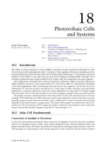
Chapter 5 introduces the power semiconductor devices and their characteristics as
part of a power electronic system. It discusses the desired characteristics to be found
in an ideal switch and provides information on components, power semiconductor
device protection, hardware issues of converters and future trends.
Chapter 6 covers in detail the thyristor-based power electronic equipment used in
power systems for reactive power control. It provides essential background theory to
understand its principle of operation and basic analytical expression for assessing its
switching behaviour. It then presents basic power electronic equipment built with
voltage-source converters. These include single-phase and three-phase circuits along
with square wave and pulse-width modulation control. It discusses the basic concepts of
multilevel converters, which are used in high power electronic equipment. Energy stor-
age systems based on superconducting material and uninterruptible power supplies are
also presented. Towards the end of the chapter, conventional HVDC systems along
with VSC-based HVDC and active filtering equipment are also presented.
Chapter 7 deals with the all-important topic of power systems harmonics. To a
greater or lesser extent all power electronic controllers generate harmonic currents,
but from the operator's perspective, and the end-user, these are parasitic or nuisance
effects. The book addresses the issue of power systems harmonics with emphasis on
electronic compensation.
Chapter 8 provides basic information on how the industry standard software
package PSCAD/EMTDC can be used to simulate and study not only the periodic
steady state response of power electronic equipment but also their transient response.
Specifically, detailed simulation examples are presented of the Static Var compensa-
tor, thyristor controlled series compensator, STATCOM, solid-state transfer switch,
DVR and shunt-connected active filters based on the VSC concept.
Dr Acha would like to acknowledge assistance received from Dr Claudio R.
Fuerte-Esquivel and Dr Hugo Ambriz-Perez in Chapter 4. Dr Agelidis wishes to
acknowledge the editorial assistance of Ms B.G. Weppler received for Chapters 5 and
6. Mr Anaya-Lara would like to express his gratitude to Mr Manual Madrigal for his
assistance in the preparation of thyristor-controlled series compensator simulations
and analysis in Chapter 8.
Enrique Acha
Vassilios G. Agelidis
Olimpo Anaya-Lara
Tim Miller
xii Preface
//SYS21/F:/PEC/REVISES_10-11-01/075065126-CH001.3D ± 1 ± [1±30/30] 17.11.2001 9:43AM
1
Electrical power
systems ± an overview
1.1 Introduction
The main elements of an electrical power system are generators, transformers,
transmission lines, loads and protection and control equipment. These elements are
interconnected so as to enable the generation of electricity in the most suitable
locations and in sufficient quantity to satisfy the customers' demand, to transmit it
to the load centres and to deliver good-quality electric energy at competitive prices.
The quality of the electricity supply may be measured in terms of:
.
constant voltage magnitude, e.g. no voltage sags
.
constant frequency
.
constant power factor
.
balanced phases
.
sinusoidal waveforms, e.g. no harmonic content
.
lack of interruptions
.
ability to withstand faults and to recover quickly.
1.2 Background
The last quarter of the nineteenth century saw the development of the electricity
supply industry as a new, promising and fast-growing activity. Since that time
electrical power networks have undergone immense transformations (Hingorani
and Gyugyi, 2000; Kundur, 1994). Owing to the relative `safety' and `cleanliness'
of electricity, it quickly became established as a means of delivering light, heat and
motive power. Nowadays it is closely linked to primary activities such as industrial
production, transport, communications and agriculture. Population growth, techno-
logical innovations and higher capital gains are just a few of the factors that have
maintained the momentum of the power industry.
//SYS21/F:/PEC/REVISES_10-11-01/075065126-CH001.3D ± 2 ± [1±30/30] 17.11.2001 9:43AM
Clearly it has not been easy for the power industry to reach its present status.
Throughout its development innumerable technical and economic problems have
been overcome, enabling the supply industry to meet the ever increasing demand
for energy with electricity at competitive prices. The generator, the incandescent
lamp and the industrial motor were the basis for the success of the earliest schemes.
Soon the transformer provided a means for improved efficiency of distribution so
that generation and transmission of alternating current over considerable distances
provided a major source of power in industry and also in domestic applications.
For many decades the trend in electric power production has been towards an inter-
connected network of transmission lines linking generators and loads into large integ-
rated systems, some of which span entire continents. The main motivation has been to
take advantage of load diversity, enabling a better utilization of primary energy resour-
ces. It may be argued that interconnection provides an alternative to a limited amount
of generation thus enhancing the security of supply (Anderson and Fouad, 1977).
Interconnection was further enhanced, in no small measure, by early break-
throughs in high-current, high-power semiconductor valve technology. Thyristor-
based high voltage direct current (HVDC) converter installations provided a means
for interconnecting power systems with different operating frequencies, e.g. 50/60 Hz,
for interconnecting power systems separated by the sea, e.g. the cross-Channel link
between England and France, and for interconnecting weak and strong power
systems (Hingorani, 1996). The rectifier and inverter may be housed within the same
converter station (back-to-back) or they may be located several hundred kilometres
apart, for bulk-power, extra-long-distance transmission. The most recent develop-
ment in HVDC technology is the HVDC system based on solid state voltage source
converters (VSCs), which enables independent, fast control of active and reactive
powers (McMurray, 1987). This equipment uses insulated gate bipolar transistors
(IGBTs) or gate turn-off thyristors (GTOs) `valves' and pulse width modulation
(PWM) control techniques (Mohan et al., 1995). It should be pointed out that this
technology was first developed for applications in industrial drive systems for
improved motor speed control. In power transmission applications this technology
has been termed HVDC Light (Asplund et al., 1998) to differentiate it from the well-
established HVDC links based on thyristors and phase control (Arrillaga, 1999).
Throughout this book, the terms HVDC Light and HVDC based on VSCs are used
interchangeably.
Based on current and projected installations, a pattern is emerging as to where this
equipment will find widespread application: deregulated market applications in
primary distribution networks, e.g. the 138 kV link at Eagle Pass, interconnecting the
Mexican and Texas networks (Asplund, 2000). The 180 MVA Directlink in Australia,
interconnecting the Queensland and New South Wales networks, is another example.
Power electronics technology has affected every aspect of electrical power
networks; not just HVDC transmission but also generation, AC transmission,
distribution and utilization. At the generation level, thyristor-based automatic
voltage regulators (AVRs) have been introduced to enable large synchronous
generators to respond quickly and accurately to the demands of interconnected
environments. Power system stabilizers (PSSs) have been introduced to prevent
power oscillations from building up as a result of sympathetic interactions between
generators. For instance, several of the large generators in Scotland are fitted with
2 Electrical power systems ± an overview
//SYS21/F:/PEC/REVISES_10-11-01/075065126-CH001.3D ± 3 ± [1±30/30] 17.11.2001 9:43AM
PSSs to ensure trouble-free operation between the Scottish power system and its
larger neighbour, the English power system (Fairnley et al., 1982). Deregulated
markets are imposing further demands on generating plant, increasing their wear
and tear and the likelihood of generator instabilities of various kinds, e.g. tran-
sient, dynamic, sub-synchronous resonance (SSR) and sub-synchronous torsional
interactions (SSTI). New power electronic controllers are being developed to help
generators operate reliably in the new market place. The thyristor-controlled
series compensator (TCSC) is being used to mitigate SSR, SSTI and to damp
power systems' oscillations (Larsen et al., 1992). Examples of where TCSCs have
been used to mitigate SSR are the TCSCs installed in the 500 kV Boneville Power
Administration's Slatt substation and in the 400 kV Swedish power network.
However, it should be noted that the primary function of the TCSC, like that of
its mechanically controlled counterpart, the series capacitor bank, is to reduce the
electrical length of the compensated transmission line. The aim is still to increase
power transfers significantly, but with increased transient stability margins.
A welcome result of deregulation of the electricity supply industry and open access
markets for electricity worldwide, is the opportunity for incorporating all forms of
renewable generation into the electrical power network. The signatories of the Kyoto
agreement in 1997 set themselves a target to lower emission levels by 20% by 2010.
As a result of this, legislation has been enacted and, in many cases, tax incentives
have been provided to enable the connection of micro-hydro, wind, photovoltaic,
wave, tidal, biomass and fuel cell generators. The power generated by some of these
sources of electricity is suitable for direct input, via a step-up transformer, into the
AC distribution system. This is the case with micro-hydro and biomass generators.
Other sources generate electricity in DC form or in AC form but with large, random
variations which prevent direct connection to the grid; for example fuel cells and
asynchronous wind generators. In both cases, power electronic converters such as
VSCs provide a suitable means for connection to the grid.
In theory, the thyristor-based static var compensator (SVC) (Miller, 1982) could be
used to perform the functions of the PSS, while providing fast-acting voltage support
at the generating substation. In practice, owing to the effectiveness of the PSS and its
relative low cost, this has not happened. Instead, the high speed of response of the
SVC and its low maintenance cost have made it the preferred choice to provide
reactive power support at key points of the transmission system, far away from the
generators. For most practical purposes they have made the rotating synchronous
compensator redundant, except where an increase in the short-circuit level is required
along with fast-acting reactive power support. Even this niche application of rotating
synchronous compensators may soon disappear since a thyristor-controlled series
reactor (TCSR) could perform the role of providing adaptive short-circuit compen-
sation and, alongside, an SVC could provide the necessary reactive power support.
Another possibility is the displacement of not just the rotating synchronous com-
pensator but also the SVC by a new breed of static compensators (STATCOMs)
based on the use of VSCs. The STATCOM provides all the functions that the SVC
can provide but at a higher speed and, when the technology reaches full maturity, its
cost will be lower. It is more compact and requires only a fraction of the land
required by an SVC installation. The VSC is the basic building block of the new gener-
ation of power controllers emerging from flexible alternating current transmission
Power electronic control in electrical systems 3
//SYS21/F:/PEC/REVISES_10-11-01/075065126-CH001.3D ± 4 ± [1±30/30] 17.11.2001 9:43AM
systems (FACTS) and Custom Power research (Hingorani and Gyugyi, 2000). In
high-voltage transmission, the most promising equipment is: the STATCOM, the
unified power flow controller (UPFC) and the HVDC Light. At the low-voltage
distribution level, the VSC provides the basis for the distribution STATCOM
(D-STATCOM), the dynamic voltage restorer (DVR), the power factor corrector
(PFC) and active filters.
1.3 General composition of the power network
For most practical purposes, the electrical power network may be divided into four
parts, namely generation, transmission, distribution and utilization. The four parts
are illustrated in Figure 1.1.
This figure gives the one-line diagram of a power network where two transmission
levels are observed, namely 400 kV and 132 kV. An expanded view of one of the
generators feeding into the high-voltage transmission network is used to indicate that
the generating plant consists of three-phase synchronous generators driven by either
hydro or steam turbines. Similarly, an expanded view of one of the load points is used
to indicate the composition of the distribution system, where voltage levels are
shown, i.e. 33 kV, 11 kV, 415 V and 240 V. Within the context of this illustration,
industrial consumers would be supplied with three-phase electricity at 11 kV and
domestic users with single-phase electricity at 240 V.
Figure 1.1 also gives examples of power electronics-based plant components and
where they might be installed in the electrical power network. In high-voltage
transmission systems, a TCSC may be used to reduce the electrical length of long
transmission lines, increasing power transfers and stability margins. An HVDC link
may be used for the purpose of long distance, bulk power transmission. An SVC or a
STATCOM may be used to provide reactive power support at a network location far
away from synchronous generators. At the distribution level, e.g. 33 kV and 11 kV, a
D-STATCOM may be used to provide voltage magnitude support, power factor
improvement and harmonic cancellation. The interfacing of embedded DC genera-
tors, such as fuel cells, with the AC distribution system would require a thyristor-
based converter or a VSC.
Also, a distinction should be drawn between conventional, large generators, e.g.
hydro, nuclear and coal, feeding directly into the high-voltage transmission, and the
small size generators, e.g. wind, biomass, micro-gas, micro-hydro, fuel cells and
photovoltaics, embedded into the distribution system. In general, embedded gener-
ation is seen as an environmentally sound way of generating electricity, with some
generators using free, renewable energy from nature as a primary energy resource,
e.g. wind, solar, micro-hydro and wave. Other embedded generators use non-renew-
able resources, but still environmentally benign, primary energy such as oxygen and
gas. Diesel generators are an example of non-renewable, non-environmentally
friendly embedded generation.
4 Electrical power systems ± an overview
//SYS21/F:/PEC/REVISES_10-11-01/075065126-CH001.3D ± 5 ± [1±30/30] 17.11.2001 9:43AM
Fig. 1.1 Power network.
Power electronic control in electrical systems 5
//SYS21/F:/PEC/REVISES_10-11-01/075065126-CH001.3D ± 6 ± [1±30/30] 17.11.2001 9:43AM
1.3.1 Generation
The large demand for electrical energy coupled with its continuous varying nature
and our inability to store electrical energy in significant quantities calls for a diversity
of generating sources in the power network. The traditional view is that the use of
different primary energy resources helps with continuity of supply and a more stable
pricing mechanism.
Most of the electricity consumed worldwide is produced by three-phase synchron-
ous generators (Kundur, 1994). However, three-phase induction generators will
increase their production share when wind generation (Heier, 1998) becomes more
widely available. Similarly, three-phase and single-phase static generators in the form
of fuel cells and photovoltaic arrays should contribute significantly to global elec-
tricity production in the future.
For system analysis purposes the synchronous machine can be seen as consisting of
a stationary part, i.e. armature or stator, and a moving part, the rotor, which under
steady state conditions rotates at synchronous speed.
Synchronous machines are grouped into two main types, according to their rotor
structure (Fitzgerald et al., 1983):
1. salient pole machines
2. round rotor machines.
Steam turbine driven generators (turbo-generators) work at high speed and have
round rotors. The rotor carries a DC excited field winding. Hydro units work at low
speed and have salient pole rotors. They normally have damper windings in addition
to the field winding. Damper windings consist of bars placed in slots on the pole faces
and connected together at both ends. In general, steam turbines contain no damper
windings but the solid steel of the rotor offers a path for eddy currents, which have
similar damping effects. For simulation purposes, the currents circulating in the solid
steel or in the damping windings can be treated as currents circulating in two closed
circuits (Kundur, 1994). Accordingly, a three-phase synchronous machine may be
assumed to have three stator windings and three rotor windings. All six windings will
be magnetically coupled.
Figure 1.2 shows the schematic diagram of the machine while Figure 1.3 shows the
coupled circuits. The relative position of the rotor with respect to the stator is given
by the angle between the rotor's direct axis and the axis of the phase A winding in
the stator. In the rotor, the direct axis (d-axis) is magnetically centred in the north
pole. A second axis located 90 electrical degrees behind the direct axis is called
the quadrature axis (q-axis).
In general, three main control systems directly affect the turbine-generator set:
1. the boiler's firing control
2. the governor control
3. the excitation system control.
Figure 1.4 shows the interaction of these controls and the turbine-generator set.
The excitation system control consists of an exciter and the AVR. The latter
regulates the generator terminal voltage by controlling the amount of current sup-
plied to the field winding by the exciter. The measured terminal voltage and the
6 Electrical power systems ± an overview
//SYS21/F:/PEC/REVISES_10-11-01/075065126-CH001.3D ± 7 ± [1±30/30] 17.11.2001 9:43AM
desired reference voltage are compared to produce a voltage error which is used to
alter the exciter output. Generally speaking, exciters can be of two types: (1) rotating;
or (2) static. Nowadays, static exciters are the preferred choice owing to their higher
rotation
d
axis
a
b
θ
c
q
axis
Fig. 1.2 Schematic diagram of a synchronous machine.
i
b
v
b
r
b
L
bb
L
aa
L
cc
i
c
v
c
r
c
i
a
v
a
r
a
i
F
v
F
r
F
i
D
i
Q
r
D
L
DD
L
FF
d
axis
r
Q
L
q
axis
Fig. 1.3 Coupled windings of a synchronous machine.
Power electronic control in electrical systems 7
//SYS21/F:/PEC/REVISES_10-11-01/075065126-CH001.3D ± 8 ± [1±30/30] 17.11.2001 9:43AM
speed of response and smaller size. They use thyristor rectifiers to adjust the field
current (Aree, 2000).
1.3.2 Transmission
Transmission networks operate at high voltage levels such as 400 kV and 275 kV,
because the transmission of large blocks of energy is more efficient at high voltages
(Weedy, 1987). Step-up transformers in generating substations are responsible for
increasing the voltage up to transmission levels and step-down transformers located
in distribution substations are responsible for decreasing the voltage to more man-
ageable levels such as 66 kV or 11 kV.
High-voltage transmission is carried by means of AC overhead transmission lines
and DC overhead transmission lines and cables. Ancillary equipment such as switch-
gear, protective equipment and reactive power support equipment is needed for the
correct functioning of the transmission system.
High-voltage transmission networks are usually `meshed' to provide redundant
paths for reliability. Figure 1.5 shows a simple power network.
Under certain operating conditions, redundant paths may give rise to circulating
power and extra losses. Flexible alternating current transmission systems controllers are
able to prevent circulating currents in meshed networks (IEEE/CIGRE, 1995).
Overhead transmission lines are used in high-voltage transmission and in distribu-
tion applications. They are built in double circuit, three-phase configuration in the
same tower, as shown in Figure 1.6.
They are also built in single circuit, three-phase configurations, as shown in
Figure 1.7.
Single and double circuit transmission lines may form busy transmission corridors.
In some cases as many as six three-phase circuits may be carried on just one tower.
In high-voltage transmission lines, each phase consists of two or four conductors
per phase, depending on their rated voltage, in order to reduce the total series
impedance of the line and to increase transmission capacity. One or two sky wires
are used for protection purposes against lightning strikes.
Underground cables are used in populated areas where overhead transmission
lines are impractical. Cables are manufactured in a variety of forms to serve different
Fig. 1.4 Main controls of a generating unit.
8 Electrical power systems ± an overview
//SYS21/F:/PEC/REVISES_10-11-01/075065126-CH001.3D ± 9 ± [1±30/30] 17.11.2001 9:43AM
Fig. 1.5 Meshed transmission network.
Fig. 1.6 Double circuit transmission line.
Power electronic control in electrical systems 9
//SYS21/F:/PEC/REVISES_10-11-01/075065126-CH001.3D ± 10 ± [1±30/30] 17.11.2001 9:43AM
applications. Figure 1.8 shows shielded, three-phase and single-phase cables; both
have a metallic screen to help confine the electromagnetic fields.
Belted cables are generally used for three-phase, low-voltage operation up to
approximately 5 kV, whilst three-conductor, shielded, compact sector cables are most
commonly used in three-phase applications at the 5±46 kV voltage range. At higher
voltages either gas or oil filled cables are used.
Power transformers are used in many different ways. Some of the most obvious
applications are:
6.9 m
27.5 m
guy
guy
2.65 m
9 m
0.46 m
0.46 m
Fig. 1.7 Single circuit transmission line.
Fig. 1.8 (a) Three-conductor, shielded, compact sector; and (b) one-conductor, shielded.
10 Electrical power systems ± an overview
//SYS21/F:/PEC/REVISES_10-11-01/075065126-CH001.3D ± 11 ± [1±30/30] 17.11.2001 9:43AM
.
as step-up transformers to increase the operating voltage from generating levels to
transmission levels;
.
as step-down transformers to decrease the operating voltage from transmission
levels to utilization levels;
.
as control devices to redirect power flows and to modulate voltage magnitude at a
specific point of the network;
.
as `interfaces' between power electronics equipment and the transmission net-
work.
For most practical purposes, power transformers may be seen as consisting of one
or more iron cores and two or three copper windings per phase. The three-phase
windings may be connected in a number of ways, e.g. star±star, star±delta and
delta±delta.
Modern three-phase power transformers use one of the following magnetic core
types: three single-phase units, a three-phase unit with three legs or a three-phase unit
with five legs.
Reactive power equipment is an essential component of the transmission system
(Miller, 1982). It is used for voltage regulation, stability enhancement and for
increasing power transfers. These functions are normally carried out with mechani-
cally controlled shunt and series banks of capacitors and non-linear reactors. How-
ever, when there is an economic and technical justification, the reactive power
support is provided by electronic means as opposed to mechanical means, enabling
near instantaneous control of reactive power, voltage magnitude and transmission
line impedance at the point of compensation.
The well-established SVC and the STATCOM, a more recent development, is the
equipment used to provide reactive power compensation (Hingorani and
Gyugyi, 2000). Figure 1.9 shows a three-phase, delta connected, thyristor-controlled
reactor (TCR) connected to the secondary side of a two-winding, three-legged
transformer. Figure 1.10 shows a similar arrangement but for a three-phase
STATCOM using GTO switches. In lower power applications, IGBT switches may
be used instead.
Although the end function of series capacitors is to provide reactive power to the
compensated transmission line, its role in power system compensation is better
understood as that of a series reactance compensator, which reduces the electrical
length of the line. Figure 1.11(a) illustrates one phase of a mechanically controlled,
series bank of capacitors whereas Figure 1.11(b) illustrates its electronically con-
trolled counterpart (Kinney et al., 1994). It should be pointed out that the latter has
the ability to exert instantaneous active power flow control.
Several other power electronic controllers have been built to provide adaptive
control to key parameters of the power system besides voltage magnitude, reactive
power and transmission line impedance. For instance, the electronic phase shifter is
used to enable instantaneous active power flow control. Nowadays, a single piece of
equipment is capable of controlling voltage magnitude and active and reactive power.
This is the UPFC, the most sophisticated power controller ever built (Gyugyi, 1992).
In its simplest form, the UPFC comprises two back-to-back VSCs, sharing a DC
capacitor. As illustrated in Figure 1.12, one VSC of the UPFC is connected in shunt
and the second VSC is connected in series with the power network.
Power electronic control in electrical systems 11
//SYS21/F:/PEC/REVISES_10-11-01/075065126-CH001.3D ± 12 ± [1±30/30] 17.11.2001 9:43AM
Fig. 1.9 Three-phase thyristor-controlled reactor connected in delta.
Fig. 1.10 Three-phase GTO-based STATCOM.
12 Electrical power systems ± an overview
//SYS21/F:/PEC/REVISES_10-11-01/075065126-CH001.3D ± 13 ± [1±30/30] 17.11.2001 9:43AM
HVDC Light is a very recent development in electric power transmission. It has
many technical and economical characteristics, which make it an ideal candidate for
a variety of transmission applications where conventional HVDC is unable
to compete. For instance, it can be used to supply passive loads, to provide reactive
power support and to improve the quality of supply in AC networks. The
installation contributes no short-circuit current and may be operated with no trans-
formers. It is said that it has brought down the economical power range of HVDC
transmission to only a few megawatts (Asplund et al., 1998). The HVDC Light at
Hellsjo
È
n is reputed to be the world's first installation and is rated at 3 MW and
Æ10 kV DC. At present, the technology enables power ratings of up to 200 MW. In
its simplest form, it comprises two STATCOMs linked by a DC cable, as illustrated
in Figure 1.13.
1.3.3 Distribution
Distribution networks may be classified as either meshed or radial. However,
it is customary to operate meshed networks in radial fashion with the help of
mechanically operated switches (Go
È
nen, 1986). It is well understood that radial
networks are less reliable than interconnected networks but distribution engineers
have preferred them because they use simple, inexpensive protection schemes, e.g.
over-current protection. Distribution engineers have traditionally argued that in
meshed distribution networks operated in radial fashion, most consumers are
brought back on supply a short time after the occurrence of a fault by moving
the network's open points. Open-point movements are carried out by reswitching
operations.
Traditional construction and operation practices served the electricity distribution
industry well for nearly a century. However, the last decade has seen a marked
increase in loads that are sensitive to poor quality electricity supply. Some large
industrial users are critically dependent on uninterrupted electricity supply and suffer
large financial losses as a result of even minor lapses in the quality of electricity
supply (Hingorani, 1995).
Fig. 1.11 One phase of a series capacitor. (a) mechanically controlled; and (b) electronically controlled.
Power electronic control in electrical systems 13
//SYS21/F:/PEC/REVISES_10-11-01/075065126-CH001.3D ± 14 ± [1±30/30] 17.11.2001 9:43AM
Fig. 1.12 Three-phase unified power flow controller.
//SYS21/F:/PEC/REVISES_10-11-01/075065126-CH001.3D ± 15 ± [1±30/30] 17.11.2001 9:43AM
Fig. 1.13 HVDC Light systems using VSCs.
//SYS21/F:/PEC/REVISES_10-11-01/075065126-CH001.3D ± 16 ± [1±30/30] 17.11.2001 9:43AM
These factors coupled with the ongoing deregulation and open access electricity
markets, where large consumers may shop around for competitively priced, high-
quality electricity, have propelled the distribution industry into unprecedented
change. On the technical front, one major development is the incorporation of power
electronics controllers in the distribution system to supply electricity with high
quality to selected customers. The generic, systematic solution being considered by the
utility to counter the problem of interruptions and low power quality at the end-user
level is known as Custom Power. This is the low voltage counterpart of the more
widely known FACTS technology.
Although FACTS and custom power initiatives share the same technological base,
they have different technical and economic objectives (Hingorani and Gyugyi, 2000).
Flexible alternating current transmission systems controllers are aimed at the trans-
mission level whereas Custom Power controllers are aimed at the distribution level, in
particular, at the point of connection of the electricity distribution company with
clients with sensitive loads and independent generators. Custom Power focuses
primarily on the reliability and quality of power flows. However, voltage regulation,
voltage balancing and harmonic cancellation may also benefit from this technology.
The STATCOM, the DVR and the solid state switch (SSS) are the best known
Custom Power equipment. The STATCOM and the DVR both use VSCs, but the
former is a shunt connected device which may include the functions of voltage
control, active filtering and reactive power control. The latter is a series connected
device which precisely compensates for waveform distortion and disturbances in the
neighbourhood of one or more sensitive loads. Figure 1.10 shows the schematic
representation of a three-phase STATCOM. Figure 1.14 shows that of a DVR and
Figure 1.15 shows one phase of a three-phase thyristor-based SSS.
The STATCOM used in Custom Power applications uses PWM switching control
as opposed to the fundamental frequency switching strategy preferred in FACTS
applications. PWM switching is practical in Custom Power because this is a relatively
low power application.
On the sustainable development front, environmentally aware consumers and
government organizations are providing electricity distribution companies with a
good business opportunity to supply electricity from renewable sources at a pre-
mium. The problem yet to be resolved in an interconnected system with a generation
mix is how to comply with the end-user's desire for electricity from a renewable
source. Clearly, a market for renewable generation has yet to be realized.
1.3.4 Utilization
The customers of electricity vendors may be classified as industrial, commercial and
domestic (Weedy, 1987). In industrialized societies, the first group may account for
as much as two fifths of total demand. Traditionally, induction motors have formed
the dominant component in the vast array of electric equipment found in industry,
both in terms of energy consumption and operational complexity. However, compu-
ter-assisted controllers and power electronics-based equipment, essential features in
modern manufacturing processes, present the current challenge in terms of ensuring
their trouble-free operation. This equipment requires to be supplied with high quality
electricity.
16 Electrical power systems ± an overview
//SYS21/F:/PEC/REVISES_10-11-01/075065126-CH001.3D ± 17 ± [1±30/30] 17.11.2001 9:43AM
Some loads draw constant current from the power system and their operation may
be affected by supply voltage and frequency variations. Examples of these loads are:
.
induction motors
.
synchronous motors
.
DC motors.
Fig. 1.14 Three-phase dynamic voltage restorer.
Fig. 1.15 Thyristor-based solid state switch.
Power electronic control in electrical systems 17
//SYS21/F:/PEC/REVISES_10-11-01/075065126-CH001.3D ± 18 ± [1±30/30] 17.11.2001 9:43AM
Other types of loads are less susceptible to voltage and frequency variations and
exhibit a constant resistance characteristic:
.
incandescent lighting
.
heating.
Large clusters of end user loads based on power electronics technology are capable of
injecting significant harmonic currents back into the network. Examples of these are:
.
colour TV sets
.
microwave ovens
.
energy saving lamps
.
computer equipment
.
industrial variable speed motor drives
.
battery recharging stations.
Electric energy storage is an area of great research activity, which over the last decade
has experienced some very significant breakthroughs, particularly with the use of
superconductivity and hydrogen related technologies. Nevertheless, for the purpose
of industrial applications it is reasonable to say that, apart from pumped hydro
storage, there is very little energy storage in the system. Thus, at any time the
following basic relation must be met:
Generation Demand Transmission Losses
Power engineers have no direct control over the electricity demand. Load shedding may
be used as a last resort but this is not applicable to normal system control. It is normally
carried out only under extreme pressure when serious faults or overloads persist.
1.4 An overview of the dynamic response of electrical
power networks
Electrical power systems aim to provide a reliable service to all consumers and should
be designed to cope with a wide range of normal, i.e. expected, operating conditions,
such as:
.
connection and disconnection of both large and small loads in any part of the
network
.
connection and disconnection of generating units to meet system demand
.
scheduled topology changes in the transmission system.
They must also cope with a range of abnormal operating conditions resulting from
faulty connections in the network, such as sudden loss of generation, phase con-
ductors falling to the ground and phase conductors coming into direct contact with
each other.
The ensuing transient phenomena that follow both planned and unplanned events
bring the network into dynamic operation. In practice, the system load and the
generation are changing continuously and the electrical network is never in a truly
steady state condition, but in a perpetual dynamic state. The dynamic performance of
18 Electrical power systems ± an overview