Tài liệu Power Electronic Handbook P22 pdf
Bạn đang xem bản rút gọn của tài liệu. Xem và tải ngay bản đầy đủ của tài liệu tại đây (132.32 KB, 7 trang )
© 2002 by CRC Press LLC
22
Principles of Magnetics
22.1 Introduction
22.2 Nature of a Magnetic Field
22.3 Electromagnetism
22.4 Magnetic Flux Density
22.5 Magnetic Circuits
22.6 Magnetic Field Intensity
22.7 Maxwell’s Equations
22.8 Inductance
22.9 Practical Considerations
22.1 Introduction
Although magnetism has been known since ancient times, the connection between electricity and mag-
netism was not discovered until the early 19th century. Electromagnetics is the study of electric and
magnetic field behavior. These fields arise from charged particles both at rest and in motion, and they
may exert forces on other charged particles and materials.
Hans Christian Oersted (a Danish scientist) demonstrated the relation between electricity and mag-
netism. In 1819, he showed that a compass needle could be deflected by a current-carrying conductor.
Andrew Ampere (1775–1836) experimented with two current-carrying conductors and found that they
repel or attract each other. He developed a concept to understand the electromagnetism that led to the
development of transformers and electric generators.
The theory of electromagnetic fields was developed by James Clerk Maxwell (Scottish scientist) and
published in 1865. His work was the culmination of a long series of experimental and theoretical research
performed by a number of other scientists over the centuries. Maxwell published a set of equations that
completely describe the electromagnetic field. He developed a unified theory of electromagnetism, and
he also predicted the existence of radio waves. Heinrich Hertz (a German physicist) proved the existence
of such waves early in the 20th century.
The electromagnetic force (emf) is one of the four known fundamental forces of nature. The emf is
responsible for the functioning of a large number of devices that are important to modern civilization
including radio, television, cellular telephones, computers, and electric machinery. The emf is caused by
an electromagnetic field that is described by two quantities, the electric field and the magnetic field, both
of which can vary in space and time.
22.2 Nature of a Magnetic Field
Magnetism can create a force between magnetic materials depending on their magnetic fields. Magnetic
fields can be produced by moving charged particles in electromagnets (e.g., electrons flowing through a
coil of wire connected to a battery) or in permanent magnets (spinning electrons within the atoms
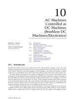
generate the field). Figure 22.1 shows Faraday’s concept of the magnetic flux lines or lines of force on a
Roman Stemprok
University of North Texas
© 2002 by CRC Press LLC
permanent bar magnet. The magnetic field is much stronger at the poles than anywhere else. The
direction of the field lines is from the North Pole to the South Pole, and the external magnetic field lines
never cross.
According to the molecular theory of magnetism, within permanent magnets there are tiny molecules
or domains that can be considered micromagnets. When they line up in a row, they combine to increase
the magnetic field strength. For example, in a normal piece of steel, the domains are arranged in random
order having positive and negative poles scattered in all directions. When the steel is magnetized, the
domains line up, allowing the whole piece of steel to act like one large magnet. By placing a magnet
beneath a piece of paper and placing iron filings on top of the piece of paper, the iron filings will arrange
themselves to look like the invisible magnetic force that surrounds the magnet. This invisible magnetic
force, which exists in the air or space around the magnet, is known as a magnetic field and the lines are
called magnetic lines of force, as shown in Fig. 22.1.
Ferromagnetic materials (e.g., iron, nickel, and cobalt) are those materials whose domains are capable
of aligning to create a magnetic field. Because of this ability, they provide an easy path for external
magnetic field lines. Elements and alloy substances differ in their ability to become magnetized by an
external field (susceptibility). Materials can be strongly magnetized by the formation domains in which
individual atoms that are weakly magnetic because of their spinning electrons align to form areas of
strong magnetism. Magnetic materials lose their magnetism if heated to or above the Curie temperature.
Other materials are mostly paramagnetic, that is, only weakly pulled toward a strong magnet. This is
because their atoms have a low level of magnetism and do not form domains. Diamagnetic materials
are the opposite of ferromagnetic materials; they are weakly repelled by a magnet since electrons within
their atoms act as electromagnets and oppose the applied magnetic force. Antiferromagnetic materials
have a very low susceptibility, which increases with temperature.
22.3 Electromagnetism
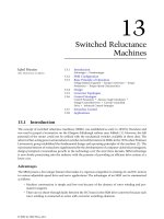
Electromagnetism is a magnetic effect due to electric currents. When a compass is placed in close
proximity to a wire carrying an electrical current, the compass needle will turn until it is at a right angle
to the conductor. The compass needle lines up in the direction of a magnetic field around the wire. It
has been found that wires carrying current have the same type of magnetic field that exists around a
magnet, as shown in Fig. 22.2. One can say that an electric current induces a magnetic field and the
field is proportional to the current,
I
.
In Fig. 22.2, the “rings” represent the magnetic lines of force existing around a wire that carries an
electric current,
I
. The magnetic field is strongest directly around the wire, and extends outward from
the wire, gradually decreasing in intensity.
The direction of a magnetic field can be predicted by use of the right-hand rule. According to the
right-hand rule, the right hand is placed around the wire that is carrying the current and the thumb
follows the direction of current flow. Then the fingers will show the direction of the magnetic field around
the conductor.
FIGURE 22.1
Magnetic field (
Φ
) of a bar magnet.
NS
© 2002 by CRC Press LLC
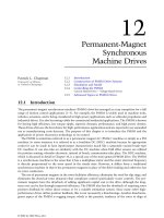
Figure 22.3 shows a case where the wire is looped into a coil. A little magnetic field wraps around
each wire and, by combining each wire turn, the coil magnetic flux (
Φ
) is created. It was found by
experimentation that if a wire is wound in the form of a coil, the total magnetic field around the coil is
magnified. This is because the magnetic fields of the turns add up to make one large flux flow, resulting
in a magnetic field (
Φ
), shown in Fig. 22.3.
22.4 Magnetic Flux Density
Fig. 22.4 shows a ferromagnetic material where the most of flux is combined to the core. Only a small amount
of the leakage flux escapes on the sides of the coil. The unit of flux (
Φ
) is the weber in the SI system. Flux
density (
B
) is the magnetic flux per unit area. If the cross-sectional area (
A
) in SI units is m
2
, then the flux
density is in webers per m
2
(Wb/m
2
), which is called tesla (T). Flux density (
B
) is defined by the total flux (
Φ
)
passing perpendicularly through an area (
A
).
(22.1)
22.5 Magnetic Circuits
Current (
I
) flowing through the coil shown in Figs. 22.3 and 22.4 creates the magnetomotive force (
ᑣ
).
The greater number of turns, the greater will be the flux. The magnetomotive force, or mmf, is defined as
(22.2)
where
N
is the number of coil turns and
I
is the current passing through the wire. For example, a coil
with 200 turns and 2 A will have an mmf of 400 At.
FIGURE 22.2
Magnetic field produced by current,
I
.
FIGURE 22.3
Magnetic field (
Φ
) produced by a coil.
Φ
Φ
I
I
South
North
Φ
Φ
B
Φ
A
----
= T()
ᑣ N · I ampere—turns, At()=
© 2002 by CRC Press LLC
The magnitude of magnetic flux depends upon the opposition presented by the magnetic circuit. The
opposition to the flux is called reluctance, which is similar to resistance in an electric circuit. The
reluctance is defined as
(22.3)
where
ᐉ
is the length of the magnetic core and
A
is a cross-sectional area. The property of the material
is characterized by its permeability,
µ
. Materials with high
µ
are called ferromagnetic materials, and the
reluctance of those materials is low.
22.6 Magnetic Field Intensity
The magnetizing force,
H
, also known as magnetic field intensity, is the mmf per unit length. The magnetic
field intensity is written as
(22.4)
Equation (22.4) describes an ability of a coil to produce magnetic flux. If, for example, in Fig. 22.4, the
coil has 1000 turns, the length of the magnetic path is 0.6 m and current through the conductor is 1 A,
then the magnetic field intensity is 600 At/m.
The field intensity and the resulting flux density are related through the permeability. The flux density is
(22.5)
where
µ
is core permeability. The core permeability is a material constant describing the level of the flux
in a material. When the material constant (
µ
) is high, the flux density will increase. The permeability
has units of webers per ampere-turn-meter in the SI system. The permeability of vacuum in free space
is
µ
o
=
4
π
×
10
−
7
(Wb/At-m). When magnetic flux propagates through magnetic media, other than
vacuum, the flux density is
(22.6)
where
µ
r
is the relative permeability. The relative permeability is 1 for a vacuum and can reach 10,000
for ferromagnetic materials. Ferromagnetic materials have regions called domains of microscopic size.
FIGURE 22.4
Magnetic flux density in a ferromagnetic material.
Core
Flux
I
A
Small
Leakage
Flux
Φ
ᑬ
ᐉ
mA
-------
At/Wb()=
H
ᑣ
ᐉ
----
NI
ᐉ
------
At/m()==
B mH T()=
B m
r
m
o
H T()=
© 2002 by CRC Press LLC
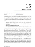
When they line up, the material is magnetized. Thus, one can increase the magnetic field until all domains
are aligned, at which point the ferromagnetic material is incapable of contributing any more magnetic
flux. At that point the material is saturated, as shown on the hysteresis curve in Fig. 22.5.
22.7 Maxwell’s Equations
Maxwell’s equations are the fundamental concept of electromagnetic (E-M) field theory. Using E-M field
theory, one can calculate important quantities such as impedance, inductance, capacitance, etc. Maxwell’s
equations in differential form are as follows:
(22.7)
(22.8)
(22.9)
(22.10)
where
H
is the magnetic field intensity (A/m),
D
is the electric flux density (C/m
2
),
B
is the magnetic
flux density (T),
J
is the current density (A/m
2
),
ρ
is the charge density (C/m
3
), and
E
is the electric field
intensity (V/m). The other relations to Maxwell’s equations are
(22.11)
(22.12)
(22.13)
where
ε
o
is the permittivity of free space (8.854
×
10
−
12
F/m) and
ε
r
is the relative dielectric constant for
a given material. In the second equation,
µ
o
is the permeability of free space (4
π
×
10
−
7
) and
µ
r
is the
relative permeability for a given material. In the third equation,
σ
is the electric conductivity (Siemens).
FIGURE 22.5
Hysteresis loop.
B
H
Residual
Magnetism
Saturation
slope = µ = B/H
o
∇ H× J
∂D
∂t
-------
+=
∇ E×
∂B
∂t
------–=
∇
·
D r=
∇
·
B 0=
D eE e
r
e
o
E==
B mH m
r
m
o
H==
J s E=