308930G hydra mate, u s english
Bạn đang xem bản rút gọn của tài liệu. Xem và tải ngay bản đầy đủ của tài liệu tại đây (1.84 MB, 68 trang )
Instructions
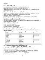
Hydra-Mate
308930G
For proportioning, mixing, pumping, and dispensing high viscosity, wide ratio
materials.
Variable Ratio Proportioner
3000 psi (21 MPa, 207 bar) Maximum Working Pressure
Important Safety Instructions
Read all warnings and instructions in
this manual. Save these instructions.
See model information on page 7.
9472a
50:1 King Pump Module Shown
Graco Inc. P.O. Box 1441 Minneapolis, MN 55440-1441
Copyright 2002, Graco Inc. is registered to I.S. EN ISO 9001
Contents
Manual Conventions . . . . . . . . . . . . . . . . . . . . . . . . 2
Theory of Operation . . . . . . . . . . . . . . . . . . . . . . . . 5
Usage . . . . . . . . . . . . . . . . . . . . . . . . . . . . . . . . . 5
Major Components . . . . . . . . . . . . . . . . . . . . . . . 5
Frame . . . . . . . . . . . . . . . . . . . . . . . . . . . . . . . . . 5
Ratio Proportioning . . . . . . . . . . . . . . . . . . . . . . . 5
System Components and Operation Overview . . 5
Models . . . . . . . . . . . . . . . . . . . . . . . . . . . . . . . . . . . 7
Installation . . . . . . . . . . . . . . . . . . . . . . . . . . . . . . . . 8
Typical Installation . . . . . . . . . . . . . . . . . . . . . . . . 8
Location . . . . . . . . . . . . . . . . . . . . . . . . . . . . . . . 8
Grounding . . . . . . . . . . . . . . . . . . . . . . . . . . . . . 10
Flushing . . . . . . . . . . . . . . . . . . . . . . . . . . . . . . 11
Setup . . . . . . . . . . . . . . . . . . . . . . . . . . . . . . . . . . . . 12
Setting the Ratio . . . . . . . . . . . . . . . . . . . . . . . . 12
Output Charts . . . . . . . . . . . . . . . . . . . . . . . . . . 13
Before Loading Material . . . . . . . . . . . . . . . . . . 17
Loading Resin . . . . . . . . . . . . . . . . . . . . . . . . . . 17
Priming Resin Pump . . . . . . . . . . . . . . . . . . . . . 18
Loading Catalyst Material . . . . . . . . . . . . . . . . . 20
Priming with Catalyst . . . . . . . . . . . . . . . . . . . . 22
Operation . . . . . . . . . . . . . . . . . . . . . . . . . . . . . . . . 24
Pressure Relief Procedure . . . . . . . . . . . . . . . . 24
Dispensing Mixed Material . . . . . . . . . . . . . . . . 25
Changing Resin Drum . . . . . . . . . . . . . . . . . . . . 27
Changing Catalyst Pail . . . . . . . . . . . . . . . . . . . 28
Filling Catalyst Pressure Tank . . . . . . . . . . . . . . 28
Troubleshooting . . . . . . . . . . . . . . . . . . . . . . . . . . . 29
Hydra-Mate Operating Pressures . . . . . . . . . . . 29
Air Supply Troubleshooting Chart . . . . . . . . . . . 30
Pump Troubleshooting Overview . . . . . . . . . . . . 31
Master Pump Troubleshooting Chart . . . . . . . . . 33
Slave Pump Troubleshooting Chart . . . . . . . . . . 34
Manifold/Mixer Troubleshooting Chart . . . . . . . . 35
Parts . . . . . . . . . . . . . . . . . . . . . . . . . . . . . . . . . . . . 38
Part No. 953100 & 570312 . . . . . . . . . . . . . . . . 38
Part No. 954900 & 965580 . . . . . . . . . . . . . . . . 40
Part No. 948094 . . . . . . . . . . . . . . . . . . . . . . . . 42
Part No. 902755 . . . . . . . . . . . . . . . . . . . . . . . . 43
Part No. 903366 . . . . . . . . . . . . . . . . . . . . . . . . 44
Part No. 954855 . . . . . . . . . . . . . . . . . . . . . . . . 46
Part No. 948109 . . . . . . . . . . . . . . . . . . . . . . . . 48
Part No. 570293 . . . . . . . . . . . . . . . . . . . . . . . . 49
Part No. 570039 . . . . . . . . . . . . . . . . . . . . . . . . 50
Part No. 947039 . . . . . . . . . . . . . . . . . . . . . . . . 51
Part No. 570342 . . . . . . . . . . . . . . . . . . . . . . . . 52
Part No. 570381 . . . . . . . . . . . . . . . . . . . . . . . . 52
Part No. 570292 . . . . . . . . . . . . . . . . . . . . . . . . 53
Part No. 570294 . . . . . . . . . . . . . . . . . . . . . . . . 54
Part No. 570295 . . . . . . . . . . . . . . . . . . . . . . . . 55
Part No. 570382 . . . . . . . . . . . . . . . . . . . . . . . . 56
Part No. 570383 . . . . . . . . . . . . . . . . . . . . . . . . 57
Part No. 570384 . . . . . . . . . . . . . . . . . . . . . . . . 58
Part No. 570184 . . . . . . . . . . . . . . . . . . . . . . . . 60
Part No. 570304 . . . . . . . . . . . . . . . . . . . . . . . . 62
Part No. 570225 . . . . . . . . . . . . . . . . . . . . . . . . 64
Part No. 233415 . . . . . . . . . . . . . . . . . . . . . . . . 66
Accessories . . . . . . . . . . . . . . . . . . . . . . . . . . . . 66
Technical Data . . . . . . . . . . . . . . . . . . . . . . . . . . . . 67
Graco Warranty . . . . . . . . . . . . . . . . . . . . . . . . . . . 68
Graco Phone Number . . . . . . . . . . . . . . . . . . . . . . 68
Manual Conventions
Warning
WARNING
A warning alerts you to the possibility of serious injury
or death if you do not follow the instructions.
Symbols, such as fire and explosion (shown), alert you
to a specific hazard and direct you to read the indicated hazard warnings (pages 3-4) for detailed information.
2
Caution
CAUTION
A caution alerts you to the possibility of damage to or
destruction of equipment if you do not follow instructions.
Note
A note indicates additional helpful information.
308930G
Warning
WARNING
SKIN INJECTION HAZARD
Spray from the gun, hose leaks, or ruptured components can inject fluid through skin and cause
extremely serious injury, including need for amputation. Fluid splashed in the eyes or on skin can cause
serious injury.
•
Fluid injected into skin might look like just a cut, but it is a serious injury. Get immediate surgical
treatment.
•
Do not point the gun at anyone or any part of the body.
•
Do not put hand or fingers over the spray tip/nozzle.
•
Do not stop or deflect leaks with hand, body, glove or rag.
•
Do not “blow back” fluid; this is not an air spray system.
•
Always have tip guard and trigger guard on the gun when spraying.
•
Check gun diffuser weekly. Refer to gun manual.
•
Check trigger safety operation before spraying. Lock trigger safety when you stop spraying.
•
Follow the Pressure Relief Procedure, page 24, if the spray tip/nozzle clogs and before cleaning,
checking or servicing the equipment.
•
Tighten fluid connections before operating equipment.
•
Check hoses, tubes, and couplings daily. Replace worn or damaged parts immediately. Do not repair
high pressure couplings; replace the entire hose.
•
Fluid hoses must have spring guards on both ends to help protect them from rupture caused by
kinks or bends near the couplings.
TOXIC FLUID HAZARD
Hazardous fluids or toxic fumes can cause serious injury or death if splashed in the eyes or on skin,
swallowed, or inhaled.
308930G
•
Know specific hazards of the fluid. Read fluid manufacturer’s warnings.
•
Wear appropriate protective clothing, gloves, eyewear, and respirator.
3
Warning
WARNING
EQUIPMENT MISUSE HAZARD
Equipment misuse can cause equipment to rupture, malfunction, or start unexpectedly and cause serious injury.
•
This equipment is for professional use only.
•
Read manuals, tags, and labels before operating equipment.
•
Use equipment only for its intended purpose. If you are uncertain, call your Graco distributor.
•
Do not alter or modify equipment. Use only genuine Graco parts and accessories.
•
Check equipment daily. Repair or replace worn or damaged parts immediately.
•
Do not exceed maximum working pressure of lowest rated system component.
•
Use fluids and solvents that are compatible with equipment wetted parts. See Technical Data section of all equipment manuals. Read fluid and solvent manufacturer’s warnings.
•
Route hoses away from traffic areas, sharp edges, moving parts, and hot surfaces. Do not expose
Graco hoses to temperatures above 180°F (82°C) or below -40°F (-40°C).
•
Comply with all applicable local, state, and national fire, electrical, and other safety regulations.
•
Do not use excessive drum separation air pressure as the drum could rupture. Make sure the drum
is not damaged and the ram plate is free to exit the drum before applying air pressure.
FIRE AND EXPLOSION HAZARD
Improper grounding, poor ventilation, open flames or sparks can cause a hazardous condition and result
in fire or explosion and serious injury.
•
Ground the equipment and object being sprayed. See Grounding, page 10.
•
If you experience static sparking or electric shock, stop operation immediately. Identify and correct
the problem.
•
Provide fresh air ventilation to avoid building up flammable fumes.
•
Keep the spray area free of debris, including solvent, rags, and gasoline.
•
Extinguish all sources of flames in the spray area, including pilot lights and cigarettes.
•
Do not turn on or off any light switch or plug or unplug electrical equipment in the spray area while
operating or if fumes are present.
•
Do not operate a gasoline engine in the spray area.
MOVING PARTS HAZARD
Moving parts, such as priming piston and wiper plate, can pinch or amputate fingers. Keep clear of moving parts when starting or operating equipment and when equipment is pressurized.
4
•
Keep hands and fingers away from the priming piston.
•
Keep hands away from the ram wiper plate and pail lip.
•
Before servicing, follow the Pressure Relief Procedure, page 24, to avoid equipment startup.
308930G
Theory of Operation
Theory of Operation
Usage
Hydra-Mate is used with two component materials
where one or both components are heavy. This is typically found in the sealant and adhesive industry, where
special requirements for loading and pumping necessitate the use of the Hydra-Mate system.
Major Components
The major components of the Hydra-Mate system
include the:
•
•
•
•
•
•
•
•
•
air motor
resin or master pump
catalyst or slave pump
ram
catalyst feed supply
mixer manifold or 2K gun
mixer
ratio check station
application device
Frame
The air motor supplies the force and motion required to
drive the system. A connecting rod couples the master
pump and air motor directly. Air motor force and motion
is transmitted through the slave linkage for synchronous
motion of the master and slave pumps.
Ratio Proportioning
The master and slave pumps are positive displacement
pumps. Positive displacement pumps displace a defined
volume of fluid for a given stroke length. The pumps displace equal amounts of material on the up and down
strokes but load or prime only on the up stroke.
The master and slave pumps displace different volumes
for the same stroke length. By adjusting the slave inlet
manifold to different points on the slave linkage, you can
change the stroke length of the slave pump, which will
change the mix ratio. You can calculate the material mix
ratio from the ratio of the pump displacement volume.
Note that the mix ratio of the Hydra-Mate is achieved by
volumetric ratio of resin to catalyst and not by weight.
These two ratios may be different depending on material
properties.
308930G
System Components and
Operation Overview
Loading the Pumps
The resin and catalyst pumps must completely fill
(prime) during the loading stroke, to ensure accurate
material displacement.
With high viscosity materials, it is difficult for material to
flow into the pump on the loading stroke. A vacuum
forms during the piston upstroke, similar to trying to
draw thick fluid into a hypodermic syringe. This condition
is called pump cavitation.
If cavitation occurs, part of the downstroke will be used
to fill the vacuum before any material is actually displaced. Since the total stroke length is used to calculate
mix ratio, this results in an off-ratio condition.
To prevent cavitation, both pumps are pressure fed. The
resin pump is pressurized by a pneumatic ram applying
a downward force on a 55 gallon plate fitted into the
drum. A shovel action pump fluid inlet further aids in
pump priming. Catalyst is delivered to the slave pump by
a pressure fed 5 gallon supply module.
Pumping the Fluids to the Mixer
Fluid is pumped through outlet blocks to a mix manifold,
where resin and catalyst are first introduced before
being mixed in a static mixer.
A check valve injects catalyst into resin at the mix manifold. When enough pressure builds up, the check valve
opens and catalyst flows into the mix manifold. This
means that during flow conditions with two positive displacement pumps linked together, the pressures at the
mix point are equal.
Any pressure differences noted on the gauges while
running reflect differences in the pressure lost by each
fluid getting from the gauge to the mix point. These
pressure drops are caused by hoses and fittings.
Mixing the Fluids
Both components leave the mix manifold and enter a
static mixer where they are mixed to a homogeneous
blend. The mixer consists of a series of left and
right-hand spiral elements.
5
Theory of Operation
When the components are pumped through the mixer,
they are progressively divided and recombined. Static
mixers used on the Hydra-Mate system include the
tri-core mixer, flexible hose mixer, or disposable mixer.
Ratio Checks
A ratio check station option verifies the volumetric mix
ratio of the two components. It is located at the outlet
blocks. With all outbound fluid valves closed, each component flows through individual ball valves opened by a
common handle into containers.
Dispense Valve
An extrusion flow gun is commonly used as the application device. It has a final or clean up mixer installed in
the handle. Various extrusion nozzles are available for
caulking or sealing applications.
Some Hydra-Mates use a 2K disposable mixer dispense
valve instead of the flow gun.
The Hydra-Mate can be used in automatic assembly lines with the addition of a logic interface.
Volumetric mix ratio can be calculated from the weight of
each component or by direct measurement. Ratio
checks are performed with the back pressures set to
actual operating pressures to simulate the normal back
pressures created by the mix manifold and gun.
6
308930G
Models
Models
Refer to form 684038 for selection information.
Model
Description
VRHM
Variable Ratio Hydra-Mate
Code A
Proportioner Pump Modules
1
2
3
5
Code B
1
2
N
Code C
1
2
3
4
N
Code D
1
2
3
4
5
6
7
8
9
Code E
1
N
308930G
25:1 Bulldog, #7 slave 7.5-16.5:1 Mix
25:1 Bulldog, #1 slave 3.7-8.0:1 Mix
50:1 Quiet King, #7 slave 7.5-16.5:1 Mix
50:1 Quiet King, #5 slave 6.5-13.5:1 Mix, T-Wipers on 55 gal. (208 l) Ram
Curative Feed Modules
5:1 Monark on 5 gal. Ram Kit
5 gal. Pressure Tank Kit
None
Boom and/or Hose Kits to Supply Gun Kits (Code D)
Boom Kit with 10 ft. (3.05 m) hoses to end for silicone or urethane
Boom Kit with 10 ft. (3.05 m) hoses to end for polysulfide
10 ft. (3.05 m) Hose Extension Kit for silicone or urethane
10 ft. (3.05 m) Hose Extension Kit for polysulfide
None
Mix and Dispense Kits (connects to one of Code C)
Resin Purge Flexible Mixer polysulfide 10 ft. (3.05 m) hoses
Resin Purge Flexible Mixer silicone 10 ft. (3.05 m) hoses
Resin Purge Flexible Mixer urethane 10 ft. (3.05 m) hoses
Resin Purge Tri-Core Mix polysulfide 10 ft. (3.05 m) hoses
Resin Purge Tri-Core Mix silicone 10 ft. (3.05 m) hoses
Resin Purge Tri-Core Mix urethane 10 ft. (3.05 m) hoses
2K-UL Disposable Mixer polysulfide 10 ft. (3.05 m) hoses
2K-UL Disposable Mixer silicone 10 ft. (3.05 m) hoses
2K-UL Disposable Mixer urethane 10 ft. (3.05 m) hoses
Accessories
Ratio Check Nozzle Kit
None
Module Number
953100
570312
954900
965580
Module Number
954855
948109
Module Number
570293
570039
570342
570381
Module Number
570292
570294
570295
570382
570383
570384
570184
570304
570225
Module Number
233415
7
Installation
Installation
Typical Installation
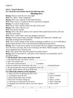
FIG. 1-3 is only a guide for selecting and installing system components and accessories. Contact your Graco distributor for assistance in designing a system to suit your needs.
Key:
A
B
C
D
E
F
G
H
I
J
K
System Air Shutoff Valve (bleed-type)
Main Air Filter
Ram Directional Valve
Ram Air Pressure Regulator
Catalyst Air Supply Valve (bleed-type)
Catalyst Air supply Regulator
Main Air Motor Shutoff Valve (bleed-type)
Catalyst Bypass Valve (back to supply)
Catalyst Outlet Filter
Catalyst Outlet Pressure Gauge
Resin Outlet Pressure Gauge
L
M
N
O
P
Q
R
S
T
U
V
Catalyst Feed Pressure Gauge
Ratio Check Outlet Valves
Catalyst Feed Pump Air Motor Lubricator
Catalyst Strainer (20 mesh)
Pail Air Blow-off and Return Line Check Valves
Vent Stick or Valve
Ram Plate with drum vent valve
Main Pump Air Regulator
Main Pump Bleed Valve
2K Ultra Lite Gun with disposable mixers
Main Motor Lubricator (not visible in FIG. 1)
K
J
I V H
VARIABLE RATIO
HYDRA-MATE
C
.O.N
CATLAYST
OUTLET
FLUID
FILTER
AIR
MOTOR
FEED
AIR
O
S
G
F
E
D
C
A
.C.N
LYC
RESIN
OUTLET
GRACO
GRACO
DRUM
R AM
M
MAIN
AIR
GRACO
OFF
MONARK
L
U
B
N
R
T
Q
P
FIG. 1: Installation with Catalyst Pail Pump Feed shown
Location
Position the ram so the air regulators for the pump and
ram are easily accessible. Ensure that there is sufficient
overhead clearance when the ram is fully raised. Refer
to the ram manual for clearance dimensions.
Check that the ram base is level in all directions. If necessary, level the base using metal shims. Secure the
base to the floor using 1/2 in. (13 mm) anchors which
are long enough to prevent the ram from tipping.
Using the holes in the ram base as a guide, drill four
holes for 1/2 in. (13 mm) anchors.
8
308930G
Installation
Key:
W
X
Y
Z
Air Line, Pressure Pot; 1/4 in. ID
Fluid Return Line; 1/4 in. npsm (fbe) x 10 ft (3.05 m)
Fluid Supply Line; 3/8 in. npt (mbe) x 10 ft (3.05 m)
Pressure Pot
AA
AB
AC
AD
Fluid Supply Line; 1/2 npt (mbe) x 10 ft (3.05 m)
Air Line, Ram; 1/4 in. ID x 10 ft (3.05 m)
Air Line, Pump; 1/2 in. ID x 10 ft (3.05 m)
Air Line, Main; 3/4 npt (mbe) x 10 ft (3.05 m)
AA
W
VARIABLE RATIO
HYDRA-MATE
C
.C.N
LYC
RESIN
OUTLET
.O .N
CATLAYST
OUTLET
FLUID
FILTER
W REF
AB
AIR
M OT O R
GRACO
FEED
AIR
AC
GRACO
X
DRUM
RAM
GRACO
Y
MAIN
AIR
O F F
MONARK
Z
GRACO
AD
AD
Catalyst Pail Pump Feed - see page 46
Catalyst Pressure Tank Feed - see page 48
FIG. 2
Key:
AE
AF
AG
AH
Mix and Gun Kit; resin purge with Tri-Core Mixer
Mix and Gun Kit; resin purge with Flexible Mixer
Catalyst Shutoff Valve
Catalyst Injector Valve
AI
AJ
AK
AL
Tri-Core Mixer
Flexible Mixer
Gun Handle Static Mixer (inside)
Gun Hose Swivel
AK
AL
AK
AJ
AL
AI
AH
AG
AH
AE
AG
AF
FIG. 3
UP
ASS
EM
BL
E
WIT
H
EN
D
CA
P
MA
RK
S
LIN
ED
308930G
9
Installation
Grounding
.
Y
W
WARNING
X
Z
The system must be properly grounded. Read warnings, page 4. Follow the instructions below.
Pump: use the ground wire and clamp (supplied). There
are two styles of grounding connections on pump air
motors.
If you have the ground screw (Z) shown in FIG. 4
(King air motor only), you need to order part no.
222011 ground wire, ring terminal, and clamp assembly
(Y). To install 222011, remove the ground screw (Z) and
insert it through the eye of ring terminal (X), then tighten
ground screw back into air motor as shown in FIG. 4.
Connect the other end of the wire to a true earth ground.
If you have the ground screw (Z) shown in FIG. 5,
loosen the grounding lug locknut (W) and washer (X).
Insert one end of the ground wire (Y) into the slot in lug
(Z) and tighten the locknut securely. Connect the other
end of the wire to a true earth ground. Order 237569
ground wire and clamp assembly.
FIG. 5 Ground Screw
Air and fluid hoses: use only electrically conductive
hoses with a maximum of 500 ft. (150 m) combined
hose length to ensure grounding continuity. Check the
electrical resistance of your air and fluid hoses. If the
total resistance to ground exceeds 29 megohms,
replace the hose immediately.
Air compressor: follow manufacturer’s recommendations.
Spray gun/dispense valve: ground through connection
to a properly grounded fluid hose and pump.
Fluid supply container: follow your local code.
Substrate: follow your local code.
Z
Y
X
Solvent pails used when flushing: follow your local
code. Use only conductive, metal pails, placed on a
grounded surface. Do not place the pail on a nonconductive surface, such as paper or cardboard, which
interrupts grounding continuity.
To maintain grounding continuity when flushing or
relieving pressure: hold a metal part of the gun/dispense valve firmly to the side of a grounded metal pail,
then trigger the gun/valve.
FIG. 4: Ground Screw (King air motor only)
10
308930G
Installation
Flushing
e. Position the solvent pail so the pump inlet is in
the solvent.
WARNING
Use solvent that is compatible with the equipment
wetted parts and the material you will dispense.
Read warnings, pages 3-4. Follow Grounding instructions, page 10.
•
The equipment was tested with light, soluble oil.
Flush the system before loading material to avoid
contamination.
•
Flush at the lowest pressure possible and check
connectors for leaks.
f.
Support the ram(s) so that the pump inlet and
piston will not hit the base plate or pail bottom.
g. Make sure both resin and catalyst outlet hoses
are open.
2. Flush the system and all hoses by very slowly opening the motor control valves until 30 psi (207 kPa, 21
bar) is shown on the resin outlet pressure gauge.
To flush the system:
1. You must remove the drum ram plate to immerse the
resin pump in a solvent pail. To remove the plate:
a. Disconnect the blow-off air line from the ram
plate.
b.
c.
Flush for 1-2 minutes, then close the motor control
valves.
CAUTION
To avoid damaging the pump, open the motor control
valves very slowly to prevent a pump runaway condition.
Disconnect the tie rod nuts from the ram cross
beam.
Remove seal plates between the pump and
ram.
d. If a pail ram is used with the catalyst supply,
remove the pail plate by loosening the 2 set
screws.
It is normal for the air valve to exhaust air when it is
partially open.
3. Check connectors for leaks and tighten them if necessary.
4. Remove the solvent pail(s) from the pump inlets.
5. Operate the pump(s) at low pressure to remove
excess solvent.
6. Reinstall the drum or pail ram plates.
308930G
11
Setup
Setup
Scale Setting
WARNING
Read warnings, pages 3-4, before operating equipment.
Refer to the Hydra-Mate Output Charts on the following
pages to set the scale. Make final adjustments after the
material is loaded. See manual 309207 for detailed ratio
check instructions.
Setting the Ratio
Volume Adjustment
To adjust the volume of material displaced by the slave
pump (AA), loosen the clamping bolts (BB) on the
adjuster at the bottom of the frame. See FIG. 7. Slide the
adjuster along the setpoint scale (CC). Move adjuster
toward the master pump to increase volume (closer
ratio) and away from the master pump to decrease volume (wider ratio). See FIG. 6. Refer to the scale on the
pivot arm. It may be necessary to jog the air motor with
the air control ball valve to reposition the adjuster. When
adjuster is in desired position, tighten the bolts (BB).
AA
CC
BB
FIG. 7
V
De
cre olum
as
e
e
Inc
rea
se
FIG. 6
12
308930G
Setup
Output Charts
Hydra-Mate Module 953100
Mix Ratio
By Volume
Scale
Setting
Slave
Stroke
Fluid/Air
Pressure Ratio
Output
Per Cycle cc's
7.40
7.75
8.14
8.57
9.04
9.57
10.17
10.85
11.62
12.52
13.56
14.79
16.27
6.32
6.00
5.70
5.41
5.13
4.85
4.57
4.29
4.02
3.76
3.50
3.25
3.00
2.20
2.10
2.00
1.90
1.80
1.70
1.60
1.50
1.40
1.30
1.20
1.10
1.00
25.90
26.04
26.18
26.33
26.47
26.62
26.77
26.92
27.07
27.23
27.38
27.54
27.70
111.99
111.38
110.78
110.17
109.56
108.96
108.35
107.74
107.14
106.53
105.93
105.32
104.71
Master Pump
Slave Pump
Motor
Type
25:1
#7
Bulldog
Number
222639
222017
902098
Area in Sq. In.
1.31
0.37
38.48
Ratio Adjustment Chart
7
Setting in Inches from Pivot or Slave Inches of Travel
6
5
4
Scale
Setting
3
Slave
Stroke
2
1
0
7.40
7.75
8.14
8.57
9.04
9.57
10.17
10.85
11.62
12.52
13.56
14.79
16.27
Desired Mix Ratio by Volume
308930G
13
Setup
Hydra-Mate Module 570312
Mix Ratio
By Volume
Scale
Setting
Slave
Stroke
Fluid/Air
Pressure Ratio
Output
Per Cycle cc's
3.70
3.87
4.07
4.28
4.52
4.79
5.09
5.42
5.81
6.26
6.78
7.40
8.14
6.32
6.00
5.70
5.41
5.13
4.85
4.57
4.29
4.02
3.76
3.50
3.25
3.00
2.20
2.10
2.00
1.90
1.80
1.70
1.60
1.50
1.40
1.30
1.20
1.10
1.00
23.14
23.37
23.60
23.84
24.08
24.32
24.57
24.82
25.09
25.35
25.62
25.90
26.18
125.33
124.12
122.90
121.69
120.48
119.26
118.05
116.84
115.63
114.41
113.20
111.99
110.78
Master Pump
Slave Pump
Motor
Type
25:1
#1
Bulldog
Number
222639
948641
902098
Area in Sq. In.
1.31
0.74
38.48
Ratio Adjustment Chart
7.00
Setting in Inches from Pivot or Slave Inches of Travel
6.00
5.00
4.00
Scale
Setting
Slave
Stroke
3.00
2.00
1.00
0.00
3.70
3.87
4.07
4.28
4.52
4.79
5.09
5.42
5.81
6.26
6.78
7.40
8.14
Desired Mix Ratio by Volume
14
308930G
Setup
Hydra-Mate Module 954900
Mix Ratio
By Volume
Scale
Setting
Slave
Stroke
Fluid/Air
Pressure Ratio
Output
Per Cycle cc's
7.40
7.75
8.14
8.57
9.04
9.57
10.17
10.85
11.62
12.52
13.56
14.79
16.27
6.32
6.00
5.70
5.41
5.13
4.85
4.57
4.29
4.02
3.76
3.50
3.25
3.00
2.20
2.10
2.00
1.90
1.80
1.70
1.60
1.50
1.40
1.30
1.20
1.10
1.00
52.97
53.26
53.55
53.85
54.14
54.44
54.75
55.06
55.37
55.68
56.00
56.32
56.65
111.99
111.38
110.78
110.17
109.56
108.96
108.35
107.74
107.14
106.53
105.93
105.32
104.71
Master Pump
Slave Pump
Motor
Type
50:1
#7
Quiet King
Number
222639
222017
220106
Area in Sq. In.
1.31
0.37
78.53
Ratio Adjustment Chart
7.00
Setting in Inches from Pivot or Slave Inches of Travel
6.00
5.00
4.00
Scale
Setting
Slave
Stroke
3.00
2.00
1.00
0.00
7.40
7.75
8.14
8.57
9.04
9.57
10.17
10.85
11.62
12.52
13.56
14.79
16.27
Desired Mix Ratio by Volume
308930G
15
Setup
Hydra-Mate Module 965580
Mix Ratio
By Volume
Scale
Setting
Slave
Stroke
Fluid/Air
Pressure Ratio
Output
Per Cycle cc's
6.16
6.46
6.78
7.14
7.53
7.98
8.48
9.04
9.69
10.43
11.30
12.33
13.56
6.32
6.00
5.70
5.41
5.13
4.85
4.57
4.29
4.02
3.76
3.50
3.25
3.00
2.20
2.10
2.00
1.90
1.80
1.70
1.60
1.50
1.40
1.30
1.20
1.10
1.00
51.74
52.07
52.40
52.74
53.09
53.43
53.79
54.14
54.50
54.87
55.24
55.62
56.00
114.66
113.93
113.20
112.47
111.75
111.02
110.29
109.56
108.84
108.11
107.38
106.65
105.93
Master Pump
Slave Pump
Motor
Type
50:1
#5
Quiet King
Number
222639
222015
220106
Area in Sq. In.
1.31
0.44
78.53
Ratio Adjustment Chart
7.00
Setting in Inches from Pivot or Slave Inches of Travel
6.00
5.00
4.00
Scale
Setting
Slave
Stroke
3.00
2.00
1.00
0.00
6.16
6.46
6.78
7.14
7.53
7.98
8.48
9.04
9.69
10.43
11.30
12.33
13.56
Desired Mix Ratio by Volume
16
308930G
Setup
Before Loading Material
3. Place the ram lever (C) in the UP position.
1. Check fluid and air lines and tighten if necessary.
2. Make sure there is a minimum overhead clearance
of 110 in. (2.79 m).
3. Fill air line lubricators for the pump motor(s) with
SAE 10 W non-detergent oil (not included).
4. Fill resin pump and catalyst feed pump wet cups
(DD) 2/3 full with Graco T.S.L. fluid (throat seal lubricant), FIG. 8.
•
•
CAUTION
As the ram rises, make sure hoses do not catch on any
components. If a hose catches, immediately stop the
ram (move lever to NEUTRAL position) and correct the
problem. Lower the ram if necessary to redirect hoses.
4. Slowly turn the ram air regulator (D) clockwise until
the ram begins rising.
If a catalyst feed tank contains urethanes, fill
the slave pump wet cup with ISO pump oil
217374 (included). Mount desiccant air dryer
on the catalyst tank air supply outlet on the
proportioner. See page 48.
S
G
ISO pump oil is used with moisture sensitive
catalysts.
DD
D
C
A
FIG. 8
5. Close (turn fully counterclockwise) all air regulators.
6. Connect the 3/4 in. (19 mm) ID x 10 ft. (3.05 m) air
hose (provided) to your air supply.
Do not use a restrictive quick-disconnect. The air
supply pressure must be consistently above the
pressure you set on the main air motor regulator.
Loading Resin
1. Make sure all air regulators are fully closed.
2. Open the main air supply shutoff valve (A), FIG. 9.
308930G
FIG. 9
5. Apply a thin coating of lubricant to the ram plate
drum seals.
6. Open the material container. Remove any packing
materials, and inspect for material contamination. If
the container has a plastic liner, pull it tightly over
the sides of the container, and secure the liner in
place with tape wrapped below the top drum rim.
7. Position the drum so it rests evenly between the
centering guides and is fully backed into the stops
located near the back of the ram base plate.
17
Setup
10. After the ram plate seals contact the drum, adjust
the ram air regulator (D) to about 30-50 psi
(207-345 kPa, 2.1-3.4 bar).
8. Open the drum vent valve (R), FIG. 10.
11. When the ram stops and material fills the bleed port
(or air stops bleeding out), close the drum vent valve
(R), FIG. 10.
Priming Resin Pump
R
If you have a disposable mixer gun, switch the air
toggle switch (on air control kit) to BYPASS.
1. Place a waste container under the pump bleed valve
(T), located behind the displacement pump outlet,
FIG. 12. Using an adjustable wrench, open the bleed
valve counterclockwise 1/3-1/2 turn.
FIG. 10
WARNING
When lowering the ram, keep hands and body away
from the ram plate and material drum. Read warnings,
page 4.
9. Lower the ram plate into the drum (move ram lever
to DOWN), FIG. 11.
T
CAUTION
Do not lower ram without a drum in place. Doing so can
damage drum centering guides.
FIG. 12
2. Slowly open the main air motor shutoff valve (G),
FIG. 9. Make sure the pump begins to cycle and
material flows from the bleed valve (T) after several
cycles of the pump, FIG. 12.
D
C
FIG. 11
If the pump does not cycle, close the air shutoff
valve (G), adjust the air motor regulator (S) up 5
psi (34 kPa, 0.3 bar) and repeat step 2, FIG. 9.
Never adjust the regulator by more than 5 psi (34
kPa, 0.3 bar) increments, FIG. 13.
3. Operate the pump until it moves smoothly in both
directions with no air popping or erratic movement,
then close the air motor shutoff valve (G), FIG. 9.
4. Close the bleed valve (T), FIG. 12.
18
308930G
Setup
5. Make sure the air motor and catalyst feed air shutoff
valves (G and E) are closed, FIG. 13.
AS
S
EM
B
LE
W
IT
H
EN
D
C
AP
M
AR
K
S
LI
N
ED
U
P
AG
FIG. 14
S
G
E
FIG. 13
6. Adjust the pump air regulator (S) to approximately
10-15 psi (69-103 kPa, 0.7-1 bar).
H
FIG. 15
7. Place the gun/resin hose over a waste container.
8. Open the catalyst bypass valve (H), FIG. 15.
9. Open the air motor shutoff valve (G) and continue
pumping until clean material, with no air pockets,
dispenses from the resin hose into the waste container, then close the shutoff valve, FIG. 13.
CAUTION
Do not operate the pump with both the catalyst shutoff
valve (AG, FIG. 14) and the catalyst bypass valve
(H, FIG. 15) in the closed position. Doing so will cause
excessive pressure to develop in catalyst lines and the
safety relief valve to open. Make sure the catalyst relief
valve is operational and free from blockage at all times.
See valve manual 308547.
308930G
19
Setup
Loading Catalyst Material
Follow the procedure for the type of supply equipment
being used.
under the wiper plate, scoop fluid from the center of
the pail to the sides to make the surface concave.
WARNING
Pneumatic Pail Ram and Piston Pump
1. Close all air regulators and air valves.
2. Set the pail ram air regulator (EE) to 40 psi (0.28
MPa, 2.8 bar), FIG. 16.
3. Push the ram directional lever (FF) to the UP position and let the ram rise to its full height.
4. Remove the catalyst pail cover. If the material has
separated, carefully stir it with a metal or plastic rod
until it is mixed. Do not use wood to stir as it can
splinter and contaminate the material. Do not mix air
into the material
5. Set the pail on the ram base. Slide it back toward
the ram tube and supports and center it under the
wiper plate (RR). To prevent air from being trapped
When operating the pump or raising or lowering the
ram, keep hands away from the wiper plate, fluid container lip, and pump intake. Read warnings, page 4.
6. With hands away from the pail and wiper plate (RR),
set the ram lever (FF) to NEUTRAL (horizontal position). Let the ram lower until the wiper plate rests on
the pail lip.
7. Ensure the pail is aligned with the wiper plate, and
open the vent ball valve (Q) to allow air to escape.
8. Push the ram directional lever (FF) DOWN and continue to lower the ram until fluid appears at the wiper
plate vent hole. Close the pail vent ball valve (Q).
EE
Q
RR
FF
FIG. 16
20
308930G
Setup
Pressure Tank
1. Remove the pressure tank lid and any items
shipped inside the tank. Make sure the tank is
clean, or use the liner supplied.
6. Pressurize the tank with dried air by opening the
catalyst air shutoff valve (E) and the pressure tank
air shutoff valve (HH), FIG. 17-18.
2. Be sure the desiccant air dryer is mounted on the
catalyst tank air supply of the proportioner air control module. See page 48.
3. Gently roll an unopened pail of catalyst on the floor
for several revolutions to mix it.
F
4. Open the pail outlet and carefully pour the catalyst
into the tank.
5. Immediately close the tank by tightening the T-handles (GG) evenly, FIG. 17.
E
FIG. 18
7. Set the catalyst air regulator (F) to 40 psi (276 kPa,
2.8 bar).
GG
HH
FIG. 17
308930G
21
Setup
Priming with Catalyst
1. Make sure the air motor and catalyst feed air shutoff
valves (G and E) are closed, FIG. 19.
AS
S
EM
B
LE
W
IT
H
EN
D
C
AP
M
AR
K
S
LI
N
ED
U
P
AG
FIG. 20
G
E
FIG. 19
H
Resin Purge Models
Follow steps 2-4. 2K UltraLite Disposable Mixer gun
models, go to step 5.
2. Fill the hose to the manifold. Disconnect the catalyst
hose [with the shutoff valve (AG)] from the mix manifold, and place the hose over a waste container,
FIG. 20.
FIG. 21
4. Close the feed air shutoff valve (E) and reconnect
the catalyst hose to the mix manifold, FIG. 19. Continue with step 8.
2K UltraLite Disposable Mixer Gun Models
Follow steps 5-10.
CAUTION
Do not operate the pump with both the catalyst shutoff
valve (AG) and the catalyst bypass valve (H) in the
closed position. FIG. 20-21. Doing so will cause excessive pressure to develop in catalyst lines and the safety
relief valve to open. Make sure the catalyst relief valve
is operational and free from blockage at all times. See
valve manual 308547.
5. Fill the hose to the gun. Trigger the gun into a waste
container.
6. Open the catalyst feed air shutoff valve (E). Catalyst
will feed through the metering cylinder to the mix
gun.
7. When bubble free material is dispensed, stop triggering the gun.
3. Open the catalyst hose shutoff valve (AG), then
slowly crack open the feed air shutoff valve (E) until
a smooth, air free flow of catalyst is dispensed.
22
308930G
Setup
All Models
8. Fill the catalyst bypass hose. Disconnect the catalyst return hose from the ram plate or pressure tank
return fitting.
9. Open the catalyst bypass valve (H), close catalyst
shutoff valve (AG), then slowly crack open the feed
air shutoff valve (E) until a smooth, air free flow of
catalyst is dispensed.
The system is now ready to dispense mixed material.
CAUTION
The materials will cure after mixing. Purge the mixer,
hose, and gun with clean material before the material
begins to cure.
10. Close the catalyst bypass valve (H) and reconnect
the catalyst return hose to the ram plate or pressure
tank.
308930G
23
Operation
Operation
Pressure Relief Procedure
5. Open the catalyst bypass valve (H) and the resin
pump bleeder valve (T), having a container ready to
catch the drainage, FIG. 23-24.
WARNING
h
Read warnings, page 3, and follow the Pressure
Relief Procedure whenever you:
• are instructed to relieve pressure
• stop dispensing
• check or service any of the equipment
• install or clean the nozzle.
1. Purge mixed material if necessary. See page 26.
2. Close the main air shutoff valve (A), FIG. 22.
H
FIG. 23
A
T
FIG. 24
FIG. 22
3. If a catalyst pressure tank is used, open its vent
(refer to page 48).
4. Hold a metal part of the gun firmly to the side of a
grounded metal pail, and trigger the gun to relieve
pressure.
24
6. Leave the bypass valve (H) open until you are ready
to dispense again.
7. If you suspect that the nozzle or hose is completely
clogged, or that pressure has not been fully relieved
after following the steps above, very slowly loosen
the tip retaining nut or hose end coupling and relieve
pressure gradually, then loosen it completely, and
clear the nozzle or hose.
308930G
Operation
Dispensing Mixed Material
CAUTION
Make sure the catalyst relief valve is operational and
free from blockage at all times. See manual 308547. If
the relief valve fails, the overpressure rupture disc
opens and catalyst is diverted to a waste container
mounted on the ram base plate.
J
K
Hydra-Mate with Resin Purge Gun Kit
1. Load the material. See page 17.
H
2. Set ratio. See page 12.
FIG. 26
3. Open the air motor and catalyst air shutoff valves (G
and E), FIG. 25. Make sure the catalyst bypass valve
is closed (H), FIG. 26.
4. Adjust the air motor air regulator (S) until resin and
catalyst outbound gauges (J and K) show the
desired pressure, FIG. 25-26.
5. Trigger the gun to dispense mixed material.
6. Adjust the catalyst supply air regulator (F) so that
catalyst inbound fluid pressure is no more than 1/4
of catalyst outbound fluid pressure.
7. Adjust the air motor air regulator (S) for the desired
flow rate.
S
G
F
E
FIG. 25
308930G
25