Tài liệu Architecture of a Database System ppt
Bạn đang xem bản rút gọn của tài liệu. Xem và tải ngay bản đầy đủ của tài liệu tại đây (909.54 KB, 119 trang )
Foundations and Trends
R
in
Databases
Vol. 1, No. 2 (2007) 141–259
c
2007 J. M. Hellerstein, M. Stonebraker
and J. Hamilton
DOI: 10.1561/1900000002
Architecture of a Database System
Joseph M. Hellerstein
1
, Michael Stonebraker
2
and James Hamilton
3
1
University of California, Berkeley, USA,
2
Massachusetts Institute of Technology, USA
3
Microsoft Research, USA
Abstract
Database Management Systems (DBMSs) are a ubiquitous and critical
component of modern computing, and the result of decades of research
and development in both academia and industry. Historically, DBMSs
were among the earliest multi-user server systems to be developed, and
thus pioneered many systems design techniques for scalability and relia-
bility now in use in many other contexts. While many of the algorithms
and abstractions used by a DBMS are textbook material, there has been
relatively sparse coverage in the literature of the systems design issues
that make a DBMS work. This paper presents an architectural dis-
cussion of DBMS design principles, including process models, parallel
architecture, storage system design, transaction system implementa-
tion, query processor and optimizer architectures, and typical shared
components and utilities. Successful commercial and open-source sys-
tems are used as points of reference, particularly when multiple alter-
native designs have been adopted by different groups.
1
Introduction
Database Management Systems (DBMSs) are complex, mission-critical
software systems. Today’s DBMSs embody decades of academic
and industrial research and intense corporate software development.
Database systems were among the earliest widely deployed online server
systems and, as such, have pioneered design solutions spanning not only
data management, but also applications, operating systems, and net-
worked services. The early DBMSs are among the most influential soft-
ware systems in computer science, and the ideas and implementation
issues pioneered for DBMSs are widely copied and reinvented.
For a number of reasons, the lessons of database systems architec-
ture are not as broadly known as they should be. First, the applied
database systems community is fairly small. Since market forces only
support a few competitors at the high end, only a handful of successful
DBMS implementations exist. The community of people involved in
designing and implementing database systems is tight: many attended
the same schools, worked on the same influential research projects, and
collaborated on the same commercial products. Second, academic treat-
ment of database systems often ignores architectural issues. Textbook
presentations of database systems traditionally focus on algorithmic
142
1.1 Relational Systems: The Life of a Query 143
and theoretical issues — which are natural to teach, study, and test —
without a holistic discussion of system architecture in full implementa-
tions. In sum, much conventional wisdom about how to build database
systems is available, but little of it has been written down or commu-
nicated broadly.
In this paper, we attempt to capture the main architectural aspects
of modern database systems, with a discussion of advanced topics. Some
of these appear in the literature, and we provide references where appro-
priate. Other issues are buried in product manuals, and some are simply
part of the oral tradition of the community. Where applicable, we use
commercial and open-source systems as examples of the various archi-
tectural forms discussed. Space prevents, however, the enumeration of
the exceptions and finer nuances that have found their way into these
multi-million line code bases, most of which are well over a decade old.
Our goal here is to focus on overall system design and stress issues
not typically discussed in textbooks, providing useful context for more
widely known algorithms and concepts. We assume that the reader
is familiar with textbook database systems material (e.g., [72] or [83])
and with the basic facilities of modern operating systems such as UNIX,
Linux, or Windows. After introducing the high-level architecture of a
DBMS in the next section, we provide a number of references to back-
ground reading on each of the components in Section 1.2.
1.1 Relational Systems: The Life of a Query
The most mature and widely used database systems in production
today are relational database management systems (RDBMSs). These
systems can be found at the core of much of the world’s application
infrastructure including e-commerce, medical records, billing, human
resources, payroll, customer relationship management and supply chain
management, to name a few. The advent of web-based commerce and
community-oriented sites has only increased the volume and breadth of
their use. Relational systems serve as the repositories of record behind
nearly all online transactions and most online content management sys-
tems (blogs, wikis, social networks, and the like). In addition to being
important software infrastructure, relational database systems serve as
144 Introduction
Fig. 1.1 Main components of a DBMS.
a well-understood point of reference for new extensions and revolutions
in database systems that may arise in the future. As a result, we focus
on relational database systems throughout this paper.
At heart, a typical RDBMS has five main components, as illustrated
in Figure 1.1. As an introduction to each of these components and the
way they fit together, we step through the life of a query in a database
system. This also serves as an overview of the remaining sections of the
paper.
Consider a simple but typical database interaction at an airport, in
which a gate agent clicks on a form to request the passenger list for a
flight. This button click results in a single-query transaction that works
roughly as follows:
1. The personal computer at the airport gate (the “client”) calls
an API that in turn communicates over a network to estab-
lish a connection with the Client Communications Manager
of a DBMS (top of Figure 1.1). In some cases, this connection
1.1 Relational Systems: The Life of a Query 145
is established between the client and the database server
directly, e.g., via the ODBC or JDBC connectivity protocol.
This arrangement is termed a “two-tier” or “client-server”
system. In other cases, the client may communicate with
a “middle-tier server” (a web server, transaction process-
ing monitor, or the like), which in turn uses a protocol to
proxy the communication between the client and the DBMS.
This is usually called a “three-tier” system. In many web-
based scenarios there is yet another “application server” tier
between the web server and the DBMS, resulting in four
tiers. Given these various options, a typical DBMS needs
to be compatible with many different connectivity protocols
used by various client drivers and middleware systems. At
base, however, the responsibility of the DBMS’ client com-
munications manager in all these protocols is roughly the
same: to establish and remember the connection state for
the caller (be it a client or a middleware server), to respond
to SQL commands from the caller, and to return both data
and control messages (result codes, errors, etc.) as appro-
priate. In our simple example, the communications manager
would establish the security credentials of the client, set up
state to remember the details of the new connection and the
current SQL command across calls, and forward the client’s
first request deeper into the DBMS to be processed.
2. Upon receiving the client’s first SQL command, the DBMS
must assign a “thread of computation” to the command. It
must also make sure that the thread’s data and control out-
puts are connected via the communications manager to the
client. These tasks are the job of the DBMS Process Man-
ager (left side of Figure 1.1). The most important decision
that the DBMS needs to make at this stage in the query
regards admission control: whether the system should begin
processing the query immediately, or defer execution until a
time when enough system resources are available to devote
to this query. We discuss Process Management in detail in
Section 2.
146 Introduction
3. Once admitted and allocated as a thread of control, the gate
agent’s query can begin to execute. It does so by invoking the
code in the Relational Query Processor (center, Figure 1.1).
This set of modules checks that the user is authorized to run
the query, and compiles the user’s SQL query text into an
internal query plan. Once compiled, the resulting query plan
is handled via the plan executor. The plan executor consists
of a suite of “operators” (relational algorithm implementa-
tions) for executing any query. Typical operators implement
relational query processing tasks including joins, selection,
projection, aggregation, sorting and so on, as well as calls
to request data records from lower layers of the system. In
our example query, a small subset of these operators — as
assembled by the query optimization process — is invoked to
satisfy the gate agent’s query. We discuss the query processor
in Section 4.
4. At the base of the gate agent’s query plan, one or more
operators exist to request data from the database. These
operators make calls to fetch data from the DBMS’ Trans-
actional Storage Manager (Figure 1.1, bottom), which man-
ages all data access (read) and manipulation (create, update,
delete) calls. The storage system includes algorithms and
data structures for organizing and accessing data on disk
(“access methods”), including basic structures like tables
and indexes. It also includes a buffer management mod-
ule that decides when and what data to transfer between
disk and memory buffers. Returning to our example, in the
course of accessing data in the access methods, the gate
agent’s query must invoke the transaction management code
to ensure the well-known “ACID” properties of transactions
[30] (discussed in more detail in Section 5.1). Before access-
ing data, locks are acquired from a lock manager to ensure
correct execution in the face of other concurrent queries. If
the gate agent’s query involved updates to the database, it
would interact with the log manager to ensure that the trans-
action was durable if committed, and fully undone if aborted.
1.1 Relational Systems: The Life of a Query 147
In Section 5, we discuss storage and buffer management in
more detail; Section 6 covers the transactional consistency
architecture.
5. At this point in the example query’s life, it has begun to
access data records, and is ready to use them to compute
results for the client. This is done by “unwinding the stack”
of activities we described up to this point. The access meth-
ods return control to the query executor’s operators, which
orchestrate the computation of result tuples from database
data; as result tuples are generated, they are placed in a
buffer for the client communications manager, which ships
the results back to the caller. For large result sets, the
client typically will make additional calls to fetch more data
incrementally from the query, resulting in multiple itera-
tions through the communications manager, query execu-
tor, and storage manager. In our simple example, at the end
of the query the transaction is completed and the connec-
tion closed; this results in the transaction manager cleaning
up state for the transaction, the process manager freeing
any control structures for the query, and the communi-
cations manager cleaning up communication state for the
connection.
Our discussion of this example query touches on many of the key
components in an RDBMS, but not all of them. The right-hand side
of Figure 1.1 depicts a number of shared components and utilities
that are vital to the operation of a full-function DBMS. The catalog
and memory managers are invoked as utilities during any transaction,
including our example query. The catalog is used by the query proces-
sor during authentication, parsing, and query optimization. The mem-
ory manager is used throughout the DBMS whenever memory needs
to be dynamically allocated or deallocated. The remaining modules
listed in the rightmost box of Figure 1.1 are utilities that run indepen-
dently of any particular query, keeping the database as a whole well-
tuned and reliable. We discuss these shared components and utilities in
Section 7.
148 Introduction
1.2 Scope and Overview
In most of this paper, our focus is on architectural fundamentals sup-
porting core database functionality. We do not attempt to provide a
comprehensive review of database algorithmics that have been exten-
sively documented in the literature. We also provide only minimal dis-
cussion of many extensions present in modern DBMSs, most of which
provide features beyond core data management but do not significantly
alter the system architecture. However, within the various sections of
this paper we note topics of interest that are beyond the scope of the
paper, and where possible we provide pointers to additional reading.
We begin our discussion with an investigation of the overall archi-
tecture of database systems. The first topic in any server system archi-
tecture is its overall process structure, and we explore a variety of viable
alternatives on this front, first for uniprocessor machines and then for
the variety of parallel architectures available today. This discussion of
core server system architecture is applicable to a variety of systems,
but was to a large degree pioneered in DBMS design. Following this,
we begin on the more domain-specific components of a DBMS. We start
with a single query’s view of the system, focusing on the relational query
processor. Following that, we move into the storage architecture and
transactional storage management design. Finally, we present some of
the shared components and utilities that exist in most DBMSs, but are
rarely discussed in textbooks.
2
Process Models
When designing any multi-user server, early decisions need to be made
regarding the execution of concurrent user requests and how these are
mapped to operating system processes or threads. These decisions have
a profound influence on the software architecture of the system, and on
its performance, scalability, and portability across operating systems.
1
In this section, we survey a number of options for DBMS process mod-
els, which serve as a template for many other highly concurrent server
systems. We begin with a simplified framework, assuming the availabil-
ity of good operating system support for threads, and we initially target
only a uniprocessor system. We then expand on this simplified discus-
sion to deal with the realities of how modern DBMSs implement their
process models. In Section 3, we discuss techniques to exploit clusters
of computers, as well as multi-processor and multi-core systems.
The discussion that follows relies on these definitions:
•
An Operating System Process combines an operating system
(OS) program execution unit (a thread of control) with an
1
Many but not all DBMSs are designed to be portable across a wide variety of host operating
systems. Notable examples of OS-specific DBMSs are DB2 for zSeries and Microsoft SQL
Server. Rather than using only widely available OS facilities, these products are free to
exploit the unique facilities of their single host.
149
150 Process Models
address space private to the process. Included in the state
maintained for a process are OS resource handles and the
security context. This single unit of program execution is
scheduled by the OS kernel and each process has its own
unique address space.
•
An Operating System Thread is an OS program execution
unit without additional private OS context and without a
private address space. Each OS thread has full access to the
memory of other threads executing within the same multi-
threaded OS Process. Thread execution is scheduled by the
operating system kernel scheduler and these threads are often
called “kernel threads” or k-threads.
•
A Lightweight Thread Package is an application-level con-
struct that supports multiple threads within a single OS
process. Unlike OS threads scheduled by the OS, lightweight
threads are scheduled by an application-level thread sched-
uler. The difference between a lightweight thread and a
kernel thread is that a lightweight thread is scheduled in
user-space without kernel scheduler involvement or knowl-
edge. The combination of the user-space scheduler and all of
its lightweight threads run within a single OS process and
appears to the OS scheduler as a single thread of execution.
Lightweight threads have the advantage of faster thread
switches when compared to OS threads since there is no
need to do an OS kernel mode switch to schedule the next
thread. Lightweight threads have the disadvantage, how-
ever, that any blocking operation such as a synchronous
I/O by any thread will block all threads in the process.
This prevents any of the other threads from making progress
while one thread is blocked waiting for an OS resource.
Lightweight thread packages avoid this by (1) issuing only
asynchronous (non-blocking) I/O requests and (2) not
invoking any OS operations that could block. Generally,
lightweight threads offer a more difficult programming model
than writing software based on either OS processes or OS
threads.
151
•
Some DBMSs implement their own lightweight thread
(LWT) packages. These are a special case of general LWT
packages. We refer to these threads as DBMS threads
and simply threads when the distinction between DBMS,
general LWT, and OS threads are unimportant to the
discussion.
•
A DBMS Client is the software component that implements
the API used by application programs to communicate with
a DBMS. Some example database access APIs are JDBC,
ODBC, and OLE/DB. In addition, there are a wide vari-
ety of proprietary database access API sets. Some programs
are written using embedded SQL, a technique of mixing pro-
gramming language statements with database access state-
ments. This was first delivered in IBM COBOL and PL/I
and, much later, in SQL/J which implements embedded
SQL for Java. Embedded SQL is processed by preproces-
sors that translate the embedded SQL statements into direct
calls to data access APIs. Whatever the syntax used in
the client program, the end result is a sequence of calls
to the DBMS data access APIs. Calls made to these APIs
are marshaled by the DBMS client component and sent to
the DBMS over some communications protocol. The proto-
cols are usually proprietary and often undocumented. In the
past, there have been several efforts to standardize client-to-
database communication protocols, with Open Group DRDA
being perhaps the best known, but none have achieved broad
adoption.
•
A DBMS Worker is the thread of execution in the DBMS
that does work on behalf of a DBMS Client. A 1:1 map-
ping exists between a DBMS worker and a DBMS Client:
the DBMS worker handles all SQL requests from a single
DBMS Client. The DBMS client sends SQL requests to the
DBMS server. The worker executes each request and returns
the result to the client. In what follows, we investigate the
different approaches commercial DBMSs use to map DBMS
workers onto OS threads or processes. When the distinction is
152 Process Models
significant, we will refer to them as worker threads or worker
processes. Otherwise, we refer to them simply as workers or
DBMS workers.
2.1 Uniprocessors and Lightweight Threads
In this subsection, we outline a simplified DBMS process model taxon-
omy. Few leading DBMSs are architected exactly as described in this
section, but the material forms the basis from which we will discuss cur-
rent generation production systems in more detail. Each of the leading
database systems today is, at its core, an extension or enhancement of
at least one of the models presented here.
We start by making two simplifying assumptions (which we will
relax in subsequent sections):
1. OS thread support: We assume that the OS provides us with
efficient support for kernel threads and that a process can
have a very large number of threads. We also assume that
the memory overhead of each thread is small and that the
context switches are inexpensive. This is arguably true on
a number of modern OS today, but was certainly not true
when most DBMSs were first designed. Because OS threads
either were not available or scaled poorly on some platforms,
many DBMSs are implemented without using the underlying
OS thread support.
2. Uniprocessor hardware: We will assume that we are design-
ing for a single machine with a single CPU. Given the ubiq-
uity of multi-core systems, this is an unrealistic assumption
even at the low end. This assumption, however, will simplify
our initial discussion.
In this simplified context, a DBMS has three natural process model
options. From the simplest to the most complex, these are: (1) process
per DBMS worker, (2) thread per DBMS worker, and (3) process pool.
Although these models are simplified, all three are in use by commercial
DBMS systems today.
2.1 Uniprocessors and Lightweight Threads 153
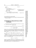
2.1.1 Process per DBMS Worker
The process per DBMS worker model (Figure 2.1) was used by early
DBMS implementations and is still used by many commercial systems
today. This model is relatively easy to implement since DBMS work-
ers are mapped directly onto OS processes. The OS scheduler man-
ages the timesharing of DBMS workers and the DBMS programmer
can rely on OS protection facilities to isolate standard bugs like mem-
ory overruns. Moreover, various programming tools like debuggers and
memory checkers are well-suited to this process model. Complicating
this model are the in-memory data structures that are shared across
DBMS connections, including the lock table and buffer pool (discussed
in more detail in Sections 6.3 and 5.3, respectively). These shared data
structures must be explicitly allocated in OS-supported shared memory
accessible across all DBMS processes. This requires OS support (which
is widely available) and some special DBMS coding. In practice, the
Fig. 2.1 Process per DBMS worker model: each DBMS worker is implemented as an OS
process.
154 Process Models
required extensive use of shared memory in this model reduces some of
the advantages of address space separation, given that a good fraction
of “interesting” memory is shared across processes.
In terms of scaling to very large numbers of concurrent connections,
process per DBMS worker is not the most attractive process model. The
scaling issues arise because a process has more state than a thread and
consequently consumes more memory. A process switch requires switch-
ing security context, memory manager state, file and network handle
tables, and other process context. This is not needed with a thread
switch. Nonetheless, the process per DBMS worker model remains pop-
ular and is supported by IBM DB2, PostgreSQL, and Oracle.
2.1.2 Thread per DBMS Worker
In the thread per DBMS worker model (Figure 2.2), a single multi-
threaded process hosts all the DBMS worker activity. A dispatcher
Fig. 2.2 Thread per DBMS worker model: each DBMS worker is implemented as an OS
thread.
2.1 Uniprocessors and Lightweight Threads 155
thread (or a small handful of such threads) listens for new DBMS client
connections. Each connection is allocated a new thread. As each client
submits SQL requests, the request is executed entirely by its corre-
sponding thread running a DBMS worker. This thread runs within the
DBMS process and, once complete, the result is returned to the client
and the thread waits on the connection for the next request from that
same client.
The usual multi-threaded programming challenges arise in this
architecture: the OS does not protect threads from each other’s mem-
ory overruns and stray pointers; debugging is tricky, especially with
race conditions; and the software can be difficult to port across OS due
to differences in threading interfaces and multi-threaded scaling. Many
of the multi-programming challenges of the thread per DBMS worker
model are also found in the process per DBMS worker model due to
the extensive use of shared memory.
Although thread API differences across OSs have been minimized
in recent years, subtle distinctions across platforms still cause hassles in
debugging and tuning. Ignoring these implementation difficulties, the
thread per DBMS worker model scales well to large numbers of con-
current connections and is used in some current-generation production
DBMS systems, including IBM DB2, Microsoft SQL Server, MySQL,
Informix, and Sybase.
2.1.3 Process Pool
This model is a variant of process per DBMS worker. Recall that the
advantage of process per DBMS worker was its implementation sim-
plicity. But the memory overhead of each connection requiring a full
process is a clear disadvantage. With process pool (Figure 2.3), rather
than allocating a full process per DBMS worker, they are hosted by a
pool of processes. A central process holds all DBMS client connections
and, as each SQL request comes in from a client, the request is given to
one of the processes in the process pool. The SQL Statement is executed
through to completion, the result is returned to the database client, and
the process is returned to the pool to be allocated to the next request.
The process pool size is bounded and often fixed. If a request comes in
156 Process Models
Fig. 2.3 Process Pool: each DBMS Worker is allocated to one of a pool of OS processes
as work requests arrive from the Client and the process is returned to the pool once the
request is processed.
and all processes are already servicing other requests, the new request
must wait for a process to become available.
Process pool has all of the advantages of process per DBMS worker
but, since a much smaller number of processes are required, is consid-
erably more memory efficient. Process pool is often implemented with
a dynamically resizable process pool where the pool grows potentially
to some maximum number when a large number of concurrent requests
arrive. When the request load is lighter, the process pool can be reduced
to fewer waiting processes. As with thread per DBMS worker, the pro-
cess pool model is also supported by a several current generation DBMS
in use today.
2.1.4 Shared Data and Process Boundaries
All models described above aim to execute concurrent client requests
as independently as possible. Yet, full DBMS worker independence and
isolation is not possible, since they are operating on the same shared
2.1 Uniprocessors and Lightweight Threads 157
database. In the thread per DBMS worker model, data sharing is easy
with all threads run in the same address space. In other models, shared
memory is used for shared data structures and state. In all three mod-
els, data must be moved from the DBMS to the clients. This implies
that all SQL requests need to be moved into the server processes and
that all results for return to the client need to be moved back out.
How is this done? The short answer is that various buffers are used.
The two major types are disk I/O buffers and client communication
buffers. We describe these buffers here, and briefly discuss policies for
managing them.
Disk I/O buffers: The most common cross-worker data dependencies
are reads and writes to the shared data store. Consequently, I/O inter-
actions between DBMS workers are common. There are two sepa-
rate disk I/O scenarios to consider: (1) database requests and (2) log
requests.
•
Database I/O Requests: The Buffer Pool. All persistent
database data is staged through the DBMS buffer pool
(Section 5.3). With thread per DBMS worker, the buffer
pool is simply a heap-resident data structure available to
all threads in the shared DBMS address space. In the other
two models, the buffer pool is allocated in shared memory
available to all processes. The end result in all three DBMS
models is that the buffer pool is a large shared data struc-
ture available to all database threads and/or processes. When
a thread needs a page to be read in from the database, it
generates an I/O request specifying the disk address, and a
handle to a free memory location (frame) in the buffer pool
where the result can be placed. To flush a buffer pool page
to disk, a thread generates an I/O request that includes the
page’s current frame in the buffer pool, and its destination
address on disk. Buffer pools are discussed in more detail in
Section 4.3.
•
Log I/O Requests: The Log Tail. The database log
(Section 6.4) is an array of entries stored on one or
more disks. As log entries are generated during transaction
158 Process Models
processing, they are staged to an in-memory queue that
is periodically flushed to the log disk(s) in FIFO order.
This queue is usually called the log tail. In many systems,
a separate process or thread is responsible for periodically
flushing the log tail to the disk.
With thread per DBMS worker, the log tail is simply
a heap-resident data structure. In the other two models,
two different design choices are common. In one approach,
a separate process manages the log. Log records are com-
municated to the log manager by shared memory or any
other efficient inter-process communications protocol. In the
other approach, the log tail is allocated in shared memory
in much the same way as the buffer pool was handled
above. The key point is that all threads and/or processes
executing database client requests need to be able to
request that log records be written and that the log tail be
flushed.
An important type of log flush is the commit transaction
flush. A transaction cannot be reported as successfully
committed until a commit log record is flushed to the log
device. This means that client code waits until the commit
log record is flushed, and that DBMS server code must
hold all resources (e.g., locks) until that time as well. Log
flush requests may be postponed for a time to allow the
batching of commit records in a single I/O request (“group
commit”).
Client communication buffers: SQL is typically used in a “pull” model:
clients consume result tuples from a query cursor by repeatedly issuing
the SQL FETCH request, which retrieve one or more tuples per request.
Most DBMSs try to work ahead of the stream of FETCH requests to
enqueue results in advance of client requests.
In order to support this prefetching behavior, the DBMS worker
may use the client communications socket as a queue for the tuples
it produces. More complex approaches implement client-side cursor
caching and use the DBMS client to store results likely to be fetched
2.2 DBMS Threads 159
in the near future rather than relying on the OS communications
buffers.
Lock table: The lock table is shared by all DBMS workers and is
used by the Lock Manager (Section 6.3) to implement database lock-
ing semantics. The techniques for sharing the lock table are the same
as those of the buffer pool and these same techniques can be used
to support any other shared data structures needed by the DBMS
implementation.
2.2 DBMS Threads
The previous section provided a simplified description of DBMS process
models. We assumed the availability of high-performance OS threads
and that the DBMS would target only uniprocessor systems. In the
remainder of this section, we relax the first of those assumptions and
describe the impact on DBMS implementations. Multi-processing and
parallelism are discussed in the next section.
2.2.1 DBMS Threads
Most of today’s DBMSs have their roots in research systems from the
1970s and commercialization efforts from the 1980s. Standard OS fea-
tures that we take for granted today were often unavailable to DBMS
developers when the original database systems were built. Efficient,
high-scale OS thread support is perhaps the most significant of these.
It was not until the 1990s that OS threads were widely implemented
and, where they did exist, the implementations varied greatly. Even
today, some OS thread implementations do not scale well enough to
support all DBMS workloads well [31, 48, 93, 94].
Hence for legacy, portability, and scalability reasons, many widely
used DBMS do not depend upon OS threads in their implementa-
tions. Some avoid threads altogether and use the process per DBMS
worker or the process pool model. Those implementing the remaining
process model choice, the thread per DBMS worker model, need a solu-
tion for those OS without good kernel thread implementations. One
means of addressing this problem adopted by several leading DBMSs
160 Process Models
was to implement their own proprietary, lightweight thread package.
These lightweight threads, or DBMS threads, replace the role of the
OS threads described in the previous section. Each DBMS thread is
programmed to manage its own state, to perform all potentially block-
ing operations (e.g., I/Os) via non-blocking, asynchronous interfaces,
and to frequently yield control to a scheduling routine that dispatches
among these tasks.
Lightweight threads are an old idea that is discussed in a retro-
spective sense in [49], and are widely used in event-loop programming
for user interfaces. The concept has been revisited frequently in the
recent OS literature [31, 48, 93, 94]. This architecture provides fast
task-switching and ease of porting, at the expense of replicating a good
deal of OS logic in the DBMS (task-switching, thread state manage-
ment, scheduling, etc.) [86].
2.3 Standard Practice
In leading DBMSs today, we find representatives of all three of the
architectures we introduced in Section 2.1 and some interesting varia-
tions thereof. In this dimension, IBM DB2 is perhaps the most interest-
ing example in that it supports four distinct process models. On OSs
with good thread support, DB2 defaults to thread per DBMS worker
and optionally supports DBMS workers multiplexed over a thread pool.
When running on OSs without scalable thread support, DB2 defaults
to process per DBMS worker and optionally supports DBMS worker
multiplexed over a process pool.
Summarizing the process models supported by IBM DB2, MySQL,
Oracle, PostgreSQL, and Microsoft SQL Server:
Process per DBMS worker:
This is the most straight-forward process model and is still heavily used
today. DB2 defaults to process per DBMS worker on OSs that do not
support high quality, scalable OS threads and thread per DBMS worker
on those that do. This is also the default Oracle process model. Oracle
also supports process pool as described below as an optional model.
PostgreSQL runs the process per DBMS worker model exclusively on
all supported operating systems.
2.3 Standard Practice 161
Thread per DBMS worker: This is an efficient model with two major
variants in use today:
1. OS thread per DBMS worker: IBM DB2 defaults to this
model when running on systems with good OS thread sup-
port and this is the model used by MySQL.
2. DBMS thread per DBMS worker: In this model, DBMS
workers are scheduled by a lightweight thread scheduler on
either OS processes or OS threads. This model avoids any
potential OS scheduler scaling or performance problems at
the expense of high implementation costs, poor development
tools support, and substantial long-standing software main-
tenance costs for the DBMS vendor. There are two main
sub-categories of this model:
a. DBMS threads scheduled on OS process :
A lightweight thread scheduler is hosted by
one or more OS processes. Sybase supports this
model as does Informix. All current generation
systems using this model implement a DBMS
thread scheduler that schedules DBMS workers
over multiple OS processes to exploit multiple
processors. However, not all DBMSs using this
model have implemented thread migration: the
ability to reassign an existing DBMS thread to a
different OS process (e.g., for load balancing).
b. DBMS threads scheduled on OS threads: Microsoft
SQL Server supports this model as a non-default
option (default is DBMS workers multiplexed over
a thread pool described below). This SQL Server
option, called Fibers, is used in some high scale
transaction processing benchmarks but, otherwise,
is in fairly light use.
Process/thread pool:
In this model, DBMS workers are multiplexed over a pool of processes.
As OS thread support has improved, a second variant of this model
162 Process Models
has emerged based upon a thread pool rather than a process pool.In
this latter model, DBMS workers are multiplexed over a pool of OS
threads:
1. DBMS workers multiplexed over a process pool : This model
is much more memory efficient than process per DBMS
worker, is easy to port to OSs without good OS thread sup-
port, and scales very well to large numbers of users. This is
the optional model supported by Oracle and the one they rec-
ommend for systems with large numbers of concurrently con-
nected users. The Oracle default model is process per DBMS
worker. Both of the options supported by Oracle are easy to
support on the vast number of different OSs they target (at
one point Oracle supported over 80 target OSs).
2. DBMS workers multiplexed over a thread pool: Microsoft
SQL Server defaults to this model and over 99% of the SQL
Server installations run this way. To efficiently support tens
of thousands of concurrently connected users, as mentioned
above, SQL Server optionally supports DBMS threads sched-
uled on OS threads.
As we discuss in the next section, most current generation com-
mercial DBMSs support intra-query parallelism: the ability to execute
all or parts of a single query on multiple processors in parallel. For
the purposes of our discussion in this section, intra-query parallelism is
the temporary assignment of multiple DBMS workers to a single SQL
query. The underlying process model is not impacted by this feature
in any way other than that a single client connection may have more
than a single DBMS worker executing on its behalf.
2.4 Admission Control
We close this section with one remaining issue related to supporting
multiple concurrent requests. As the workload in any multi-user system
increases, throughput will increase up to some maximum. Beyond this
point, it will begin to decrease radically as the system starts to thrash.
As with OSs, thrashing is often the result of memory pressure: the
2.4 Admission Control 163
DBMS cannot keep the “working set” of database pages in the buffer
pool, and spends all its time replacing pages. In DBMSs, this is particu-
larly a problem with query processing techniques like sorting and hash
joins that tend to consume large amounts of main memory. In some
cases, DBMS thrashing can also occur due to contention for locks: trans-
actions continually deadlock with each other and need to be rolled back
and restarted [2]. Hence any good multi-user system has an admission
control policy, which does not accept new work unless sufficient DBMS
resources are available. With a good admission controller, a system will
display graceful degradation under overload: transaction latencies will
increase proportionally to the arrival rate, but throughput will remain
at peak.
Admission control for a DBMS can be done in two tiers. First, a
simple admission control policy may be in the dispatcher process to
ensure that the number of client connections is kept below a threshold.
This serves to prevent overconsumption of basic resources like network
connections. In some DBMSs this control is not provided, under the
assumption that it is handled by another tier of a multi-tier system, e.g.,
application servers, transaction processing monitors, or web servers.
The second layer of admission control must be implemented directly
within the core DBMS relational query processor. This execution
admission controller runs after the query is parsed and optimized, and
determines whether a query is postponed, begins execution with fewer
resources, or begins execution without additional constraints. The exe-
cution admission controller is aided by information from the query
optimizer that estimates the resources that a query will require and
the current availability of system resources. In particular, the opti-
mizer’s query plan can specify (1) the disk devices that the query will
access, and an estimate of the number of random and sequential I/Os
per device, (2) estimates of the CPU load of the query based on the
operators in the query plan and the number of tuples to be processed,
and, most importantly (3) estimates about the memory footprint of
the query data structures, including space for sorting and hashing
large inputs during joins and other query execution tasks. As noted
above, this last metric is often the key for an admission controller,
since memory pressure is typically the main cause of thrashing. Hence
164 Process Models
many DBMSs use memory footprint and the number of active DBMS
workers as the main criterion for admission control.
2.5 Discussion and Additional Material
Process model selection has a substantial influence on DBMS scaling
and portability. As a consequence, three of the more broadly used com-
mercial systems each support more than one process model across their
product line. From an engineering perspective, it would clearly be much
simpler to employ a single process model across all OSs and at all scal-
ing levels. But, due to the vast diversity of usage patterns and the
non-uniformity of the target OSs, each of these three DBMSs have
elected to support multiple models.
Looking forward, there has been significant interest in recent years
in new process models for server systems, motivated by changes in
hardware bottlenecks, and by the scale and variability of workload on
the Internet well [31, 48, 93, 94]. One theme emerging in these designs
is to break down a server system into a set of independently scheduled
“engines,” with messages passed asynchronously and in bulk between
these engines. This is something like the “process pool” model above,
in that worker units are reused across multiple requests. The main
novelty in this recent research is to break the functional granules of
work in a more narrowly scoped task-specific manner than was done
before. This results in many-to-many relationship between workers and
SQL requests — a single query is processed via activities in multiple
workers, and each worker does its own specialized tasks for many SQL
requests. This architecture enables more flexible scheduling choices —
e.g., it allows dynamic trade-offs between allowing a single worker to
complete tasks for many queries (perhaps to improve overall system
throughput), or to allow a query to make progress among multiple
workers (to improve that query’s latency). In some cases this has been
shown to have advantages in processor cache locality, and in the ability
to keep the CPU busy from idling during cache misses in hardware.
Further investigation of this idea in the DBMS context is typified by
the StagedDB research project [35], which is a good starting point for
additional reading.
3
Parallel Architecture: Processes and Memory
Coordination
Parallel hardware is a fact of life in modern servers and comes in a
variety of configurations. In this section, we summarize the standard
DBMS terminology (introduced in [87]), and discuss the process models
and memory coordination issues in each.
3.1 Shared Memory
A shared-memory parallel system (Figure 3.1) is one in which all pro-
cessors can access the same RAM and disk with roughly the same
performance. This architecture is fairly standard today — most server
hardware ships with between two and eight processors. High-end
machines can ship with dozens of processors, but tend to be sold at
a large premium relative to the processing resources provided. Highly
parallel shared-memory machines are one of the last remaining “cash
cows” in the hardware industry, and are used heavily in high-end online
transaction processing applications. The cost of server hardware is usu-
ally dwarfed by costs of administering the systems, so the expense of
165