Metal forming
Bạn đang xem bản rút gọn của tài liệu. Xem và tải ngay bản đầy đủ của tài liệu tại đây (27.87 MB, 573 trang )
Metal Forming Handbook
Metal Forming Handbook /Schuler (c) Springer-Verlag Berlin Heidelberg 1998
3
Berlin
Heidelberg
New York
Barcelona
Budapest
Hong Kong
London
Milan
Paris
Santa Clara
Singapore
Tokyo
Metal Forming Handbook /Schuler (c) Springer-Verlag Berlin Heidelberg 1998
METAL FORMING
HANDBOOK
123
Metal Forming Handbook /Schuler (c) Springer-Verlag Berlin Heidelberg 1998
SCHULER GmbH
Bahnhofstr. 41
73033 Göppingen
Germany
Consulting editor: Professor Taylan Altan
Director, Engineering Research Center for Net Shape Manufacturing
The Ohio State University, USA
Cataloging-in-Publication Data applied for
Die Deutsche Bibliothek – CIP-Einheitsaufnahme
Metal forming handbook / Schuler. – Berlin ; Heidelberg ; New York ; Barcelona ;
Budapest ; Hong Kong ; London ; Milan ; Paris ; Santa Clara ; Singapore ; Tokyo :
Springer, 1998
Dt. Ausg. u. d. T.: Handbuch der Umformtechnik
ISBN 3-540-61185-1
ISBN 3-540-61185-1 Springer-Verlag Berlin Heidelberg New York
This work is subject to copyright.All rights are reserved,whether the whole part of the material is concerned,
specifically the rights of translation, reprinting, reuse of illustrations, recitation, broadcasting, reproduction
on microfilm or in any other way, and storage in data banks. Duplication of this publication or parts thereof
is permitted only under the provisions of the German Copyright Law of September 9, 1965, in its current ver-
sion, and permission for use must always be obtained from Springer-Verlag. Violations are liable for prose-
cution under the German Copyright Law
.
© Springer-Verlag Berlin Heidelberg 1998
Printed in Germany
The use of general descriptive names, registered names, trademarks, etc. in this publication does not imply,
even in the absence of a specific statement, that such names are exempt from the relevant protective laws and
regulations and therefore free for general use.
Cover design by MEDIO, Berlin
Layout design and data conversion by MEDIO, Berlin
Printing and binding by Konrad Triltsch Druck- und Verlagsanstalt,Würzburg
SPIN: 10514857 3020/ 62/ 5 4 3 2 1 0 – Printed on acid-free paper.
Metal Forming Handbook /Schuler (c) Springer-Verlag Berlin Heidelberg 1998
Preface
Following the long tradition of the Schuler Company, the Metal For-
ming Handbook presents the scientific fundamentals of metal forming
technology in a way which is both compact and easily understood.
Thus, this book makes the theory and practice of this field accessible to
teaching and practical implementation.
The first Schuler “Metal Forming Handbook” was published in 1930.
The last edition of 1966, already revised four times, was translated into
a number of languages, and met with resounding approval around the
globe.
Over the last 30 years, the field of forming technology has been rad-
ically changed by a number of innovations. New forming techniques
and extended product design possibilities have been developed and
introduced. This Metal Forming Handbook has been fundamentally
revised to take account of these technological changes. It is both a text-
book and a reference work whose initial chapters are concerned to pro-
vide a survey of the fundamental processes of forming technology and
press design. The book then goes on to provide an in-depth study of the
major fields of sheet metal forming, cutting, hydroforming and solid
forming. A large number of relevant calculations offers state of the art
solutions in the field of metal forming technology. In presenting tech-
nical explanations, particular emphasis was placed on easily under-
standable graphic visualization. All illustrations and diagrams were
compiled using a standardized system of functionally oriented color
codes with a view to aiding the reader’s understanding.
It is sincerely hoped that this Handbook helps not only disseminate
specialized knowledge but also provides an impetus for dialogue
between the fields of production engineering, production line con-
struction, teaching and research.
Metal Forming Handbook /Schuler (c) Springer-Verlag Berlin Heidelberg 1998
This Handbook is the product of dedicated commitment and the wide
range of specialized knowledge contributed by many employees of the
SCHULER Group in close cooperation with Prof. Dr Ing. H. Hoffmann
and Dipl Ing. M. Kasparbauer of the utg, Institute for Metal Forming
and Casting at the Technical University of Munich. In close cooperation
with the SCHULER team, they have created a solid foundation for the
practical and scientific competence presented in this Handbook. We
wish to offer our sincere thanks and appreciation to all those involved.
Goeppingen, March 1998
Schuler GmbH
Board of Management
VI
Metal Forming Handbook
Metal Forming Handbook /Schuler (c) Springer-Verlag Berlin Heidelberg 1998
Contributors
ADAM, K., Dipl Ing. (FH), SMG Süddeutsche Maschinenbau GmbH & Co
BAREIS, A., Dipl Ing. (FH), Schuler Pressen GmbH & Co
BIRZER, F., Prof. Dipl Ing., Feintool AG
BLASIG, N., Dipl Ing. (FH), Schleicher Automation GmbH & Co
BRANDSTETTER, R., Dipl Ing. (FH), Schuler Pressen GmbH & Co
BREUER, W., Dipl Ing., Schuler Pressen GmbH & Co
FRONTZEK, H., Dr Ing., Schuler GmbH
HOFFMANN, H., Prof. Dr Ing., Lehrstuhl für Umformtechnik und Gieße-
reiwesen, Technische Universität München
JAROSCH, B., Dipl Ing. (FH), Schuler Pressen GmbH & Co
KÄSMACHER, H., SMG Engineering für Industrieanlagen GmbH
KASPARBAUER, M., Dipl Ing., Lehrstuhl für Umformtechnik und Gießerei-
wesen, Technische Universität München
KELLENBENZ, R., Dipl Ing. (FH), Schuler Pressen GmbH & Co
KIEFER, A., Dipl Ing. (BA), GMG Automation GmbH & Co
KLEIN, P., Gräbener Pressensysteme GmbH & Co. KG
KLEMM, P., Dr Ing., Schuler Pressen GmbH & Co
KNAUß, V., Dipl Ing. (FH), Schuler Werkzeuge GmbH & Co
KOHLER, H., Dipl Ing., Schuler Guß GmbH & Co
KÖRNER, E., Dr Ing., Schuler Pressen GmbH & Co
KUTSCHER,
H W.,Dipl Ing.(FH), Gräbener Pressensysteme GmbH & Co. KG
LEITLOFF, F U., Dr Ing., Schäfer Hydroforming GmbH & Co
MERKLE, D., Schuler Pressen GmbH & Co
OSEN, W., Dr Ing., SMG Süddeutsche Maschinenbau GmbH & Co
PFEIFLE, P., Dipl Ing. (FH), Schuler Pressen GmbH & Co
REITMEIER, C., Dipl Ing., Schäfer Hydroforming GmbH & Co
REMPPIS, M., Ing. grad., Schuler Pressen GmbH & Co
ROSENAUER, K., Dipl Ing. (FH), Schuler Werkzeuge GmbH & Co
Metal Forming Handbook /Schuler (c) Springer-Verlag Berlin Heidelberg 1998
SCHÄFER, A.W., Schäfer Hydroforming GmbH & Co
SCHMID, W., Dipl Ing. (FH), Schuler Werkzeuge GmbH & Co
SCHMITT, K. P., Schuler Pressen GmbH & Co
SCHNEIDER, F., Dipl Ing. (FH), Schuler Pressen GmbH & Co
SIMON, H., Dr Ing., Schuler Werkzeuge GmbH & Co
STEINMETZ, M., Dipl Wirt Ing., SMG Engineering für Industrieanlagen
GmbH
STROMMER, K., Dipl Ing. (FH), Schuler Pressen GmbH & Co
VOGEL, N., Dipl Ing., Schleicher Automation GmbH & Co
WEGENER, K., Dr Ing., Schuler Pressen GmbH & Co
VIII
Metal Forming Handbook
Metal Forming Handbook /Schuler (c) Springer-Verlag Berlin Heidelberg 1998
Contents
Index of formula symbols . . . . . . . . . . . . . . . . . . . . . . . . . . . . . . . XV
1 Introduction . . . . . . . . . . . . . . . . . . . . . . . . . . . . . . . . . . . . . . . . 1
2 Basic principles of metal forming . . . . . . . . . . . . . . . . . . . . . . 5
2.1 Methods of forming and cutting technology . . . . . . . . . 5
2.1.1 Summary . . . . . . . . . . . . . . . . . . . . . . . . . . . . . . . . . 5
2.1.2 Forming . . . . . . . . . . . . . . . . . . . . . . . . . . . . . . . . . . 6
2.1.3 Dividing . . . . . . . . . . . . . . . . . . . . . . . . . . . . . . . . . . 19
2.1.4 Combinations of processes in manufacturing . . . . . 22
2.2 Basic terms . . . . . . . . . . . . . . . . . . . . . . . . . . . . . . . . . . . . . 25
2.2.1 Flow condition and flow curve. . . . . . . . . . . . . . . . . 25
2.2.2 Deformation and material flow . . . . . . . . . . . . . . . . 26
2.2.3 Force and work . . . . . . . . . . . . . . . . . . . . . . . . . . . . . 28
2.2.4 Formability . . . . . . . . . . . . . . . . . . . . . . . . . . . . . . . . 30
2.2.5 Units of measurement . . . . . . . . . . . . . . . . . . . . . . . 31
Bibliography . . . . . . . . . . . . . . . . . . . . . . . . . . . . . . . . . . . . . . . . . 32
3 Fundamentals of press design. . . . . . . . . . . . . . . . . . . . . . . . . . 33
3.1 Press types and press construction. . . . . . . . . . . . . . . . . . 33
3.1.1 Press frame . . . . . . . . . . . . . . . . . . . . . . . . . . . . . . . . 34
3.1.2 Slide drive . . . . . . . . . . . . . . . . . . . . . . . . . . . . . . . . . 37
3.1.3 Drive systems for deep drawing presses . . . . . . . . . . 41
3.1.4 Draw cushions . . . . . . . . . . . . . . . . . . . . . . . . . . . . . 44
Metal Forming Handbook /Schuler (c) Springer-Verlag Berlin Heidelberg 1998
3.2 Mechanical presses . . . . . . . . . . . . . . . . . . . . . . . . . . . . . . 49
3.2.1 Determination of characteristic data . . . . . . . . . . . 49
3.2.2 Types of drive system . . . . . . . . . . . . . . . . . . . . . . . 54
3.2.3 Drive motor and flywheel . . . . . . . . . . . . . . . . . . . . 60
3.2.4 Clutch and brake . . . . . . . . . . . . . . . . . . . . . . . . . . 61
3.2.5 Longitudinal and transverse shaft drive . . . . . . . . . 63
3.2.6 Gear drives . . . . . . . . . . . . . . . . . . . . . . . . . . . . . . . 65
3.2.7 Press crown assembly . . . . . . . . . . . . . . . . . . . . . . . 66
3.2.8 Slide and blank holder . . . . . . . . . . . . . . . . . . . . . . 66
3.2.9 Pneumatic system . . . . . . . . . . . . . . . . . . . . . . . . . . 70
3.2.10 Hydraulic system . . . . . . . . . . . . . . . . . . . . . . . . . . . 71
3.2.11 Lubrication . . . . . . . . . . . . . . . . . . . . . . . . . . . . . . . 72
3.3 Hydraulic presses . . . . . . . . . . . . . . . . . . . . . . . . . . . . . . . 73
3.3.1 Drive system . . . . . . . . . . . . . . . . . . . . . . . . . . . . . . 73
3.3.2 Hydraulic oil . . . . . . . . . . . . . . . . . . . . . . . . . . . . . . 77
3.3.3 Parallelism of the slide . . . . . . . . . . . . . . . . . . . . . . 80
3.3.4 Stroke limitation and damping . . . . . . . . . . . . . . . 82
3.3.5 Slide locking . . . . . . . . . . . . . . . . . . . . . . . . . . . . . . 83
3.4 Changing dies . . . . . . . . . . . . . . . . . . . . . . . . . . . . . . . . . . 86
3.4.1 Die handling . . . . . . . . . . . . . . . . . . . . . . . . . . . . . . 86
3.4.2 Die clamping devices . . . . . . . . . . . . . . . . . . . . . . . 91
3.5 Press control systems . . . . . . . . . . . . . . . . . . . . . . . . . . . . 94
3.5.1 Functions of the control system . . . . . . . . . . . . . . . 94
3.5.2 Electrical components of presses . . . . . . . . . . . . . . 94
3.5.3 Operating and visualization system . . . . . . . . . . . . 95
3.5.4 Structure of electrical control systems . . . . . . . . . . 97
3.5.5 Functional structure of the control system . . . . . . 99
3.5.6 Major electronic control components . . . . . . . . . . 99
3.5.7 Architecture and hardware configuration . . . . . . . 101
3.5.8 Architecture of the PLC software . . . . . . . . . . . . . . 101
3.5.9 Future outlook . . . . . . . . . . . . . . . . . . . . . . . . . . . . 102
3.6 Press safety and certification . . . . . . . . . . . . . . . . . . . . . . 106
3.6.1 Accident prevention . . . . . . . . . . . . . . . . . . . . . . . . 106
3.6.2 Legislation . . . . . . . . . . . . . . . . . . . . . . . . . . . . . . . . 107
3.6.3 European safety requirements . . . . . . . . . . . . . . . . 107
3.6.4 CE marking . . . . . . . . . . . . . . . . . . . . . . . . . . . . . . . 111
X
Metal Forming Handbook
Metal Forming Handbook /Schuler (c) Springer-Verlag Berlin Heidelberg 1998
3.6.5 Measures to be undertaken by the user . . . . . . . . . 115
3.6.6 Safety requirements in the USA . . . . . . . . . . . . . . . 117
3.7 Casting components for presses . . . . . . . . . . . . . . . . . . . 120
Bibliography . . . . . . . . . . . . . . . . . . . . . . . . . . . . . . . . . . . . . . . . . 122
4 Sheet metal forming and blanking . . . . . . . . . . . . . . . . . . . . 123
4.1 Principles of die manufacture . . . . . . . . . . . . . . . . . . . . . 123
4.1.1 Classification of dies . . . . . . . . . . . . . . . . . . . . . . . . 123
4.1.2 Die development . . . . . . . . . . . . . . . . . . . . . . . . . . 128
4.1.3 Die materials . . . . . . . . . . . . . . . . . . . . . . . . . . . . . . 142
4.1.4 Casting of dies . . . . . . . . . . . . . . . . . . . . . . . . . . . . . 142
4.1.5 Try-out equipment . . . . . . . . . . . . . . . . . . . . . . . . . 148
4.1.6 Transfer simulators . . . . . . . . . . . . . . . . . . . . . . . . . 154
4.2 Deep drawing and stretch drawing . . . . . . . . . . . . . . . . . 156
4.2.1 Forming process . . . . . . . . . . . . . . . . . . . . . . . . . . . 156
4.2.2 Materials for sheet metal forming . . . . . . . . . . . . . 174
4.2.3 Friction, wear and lubrication during
sheet metal forming . . . . . . . . . . . . . . . . . . . . . . . . 179
4.2.4 Hydro-mechanical deep drawing . . . . . . . . . . . . . . 185
4.2.5 Active hydro-mechanical drawing . . . . . . . . . . . . . 188
4.3 Coil lines . . . . . . . . . . . . . . . . . . . . . . . . . . . . . . . . . . . . . . 194
4.4 Sheet metal forming lines . . . . . . . . . . . . . . . . . . . . . . . . 198
4.4.1 Universal presses . . . . . . . . . . . . . . . . . . . . . . . . . . . 198
4.4.2 Production lines for the manufacture of
flat radiator plates . . . . . . . . . . . . . . . . . . . . . . . . . 208
4.4.3 Lines for side member manufacture . . . . . . . . . . . . 210
4.4.4 Destackers and blank turnover stations . . . . . . . . 217
4.4.5 Press lines . . . . . . . . . . . . . . . . . . . . . . . . . . . . . . . . 222
4.4.6 Transfer presses for small and
medium sized parts . . . . . . . . . . . . . . . . . . . . . . . . . 229
4.4.7 Large-panel tri-axis transfer presses . . . . . . . . . . . . 234
4.4.8 Crossbar transfer presses . . . . . . . . . . . . . . . . . . . . . 243
4.4.9 Presses for plastics . . . . . . . . . . . . . . . . . . . . . . . . . . 250
4.4.10 Stacking units for finished parts . . . . . . . . . . . . . . . 252
4.4.11 Control systems for large-panel transfer presses . . 254
XI
Contents
Metal Forming Handbook /Schuler (c) Springer-Verlag Berlin Heidelberg 1998
4.5 Blanking processes . . . . . . . . . . . . . . . . . . . . . . . . . . . . . . 268
4.6 Shearing lines . . . . . . . . . . . . . . . . . . . . . . . . . . . . . . . . . . 284
4.6.1 Slitting lines . . . . . . . . . . . . . . . . . . . . . . . . . . . . . . 284
4.6.2 Blanking lines . . . . . . . . . . . . . . . . . . . . . . . . . . . . . 286
4.6.3 High-speed blanking lines . . . . . . . . . . . . . . . . . . . 291
4.6.4 Lines for the production of
electric motor laminations . . . . . . . . . . . . . . . . . . . 296
4.6.5 Production and processing of tailored blanks . . . . 310
4.6.6 Perforating presses . . . . . . . . . . . . . . . . . . . . . . . . . 314
4.6.7 Control systems for blanking presses . . . . . . . . . . . 320
4.7 Fine blanking . . . . . . . . . . . . . . . . . . . . . . . . . . . . . . . . . . . 330
4.7.1 Fine blanking process . . . . . . . . . . . . . . . . . . . . . . . 330
4.7.2 Fine blanking materials, forces, quality
characteristics and part variety . . . . . . . . . . . . . . . . 338
4.7.3 Fine blanking tools . . . . . . . . . . . . . . . . . . . . . . . . . 351
4.7.4 Fine blanking presses and lines . . . . . . . . . . . . . . . 359
4.8 Bending . . . . . . . . . . . . . . . . . . . . . . . . . . . . . . . . . . . . . . . 366
4.8.1 Bending process . . . . . . . . . . . . . . . . . . . . . . . . . . . 366
4.8.2 Roll forming and variety of sections . . . . . . . . . . . . 373
4.8.3 Roller straightening . . . . . . . . . . . . . . . . . . . . . . . . 383
4.9 Organization of stamping plants . . . . . . . . . . . . . . . . . . 389
4.9.1 Design . . . . . . . . . . . . . . . . . . . . . . . . . . . . . . . . . . . 389
4.9.2 Layout . . . . . . . . . . . . . . . . . . . . . . . . . . . . . . . . . . . 391
4.9.3 Quality assurance through quality control . . . . . . 398
Bibliography . . . . . . . . . . . . . . . . . . . . . . . . . . . . . . . . . . . . . . . . . 403
5 Hydroforming . . . . . . . . . . . . . . . . . . . . . . . . . . . . . . . . . . . . . . 405
5.1 General . . . . . . . . . . . . . . . . . . . . . . . . . . . . . . . . . . . . . . . . 405
5.2 Process technology and example applications . . . . . . . 405
5.2.1 Process technology . . . . . . . . . . . . . . . . . . . . . . . . . 405
5.2.2 Types of hydroformed components . . . . . . . . . . . . 408
5.2.3 Fields of application . . . . . . . . . . . . . . . . . . . . . . . . 410
XII
Metal Forming Handbook
Metal Forming Handbook /Schuler (c) Springer-Verlag Berlin Heidelberg 1998
5.3 Component development . . . . . . . . . . . . . . . . . . . . . . . . . 413
5.3.1 User-oriented project management . . . . . . . . . . . . 413
5.3.2 Feasibility studies . . . . . . . . . . . . . . . . . . . . . . . . . . 414
5.3.3 Component design . . . . . . . . . . . . . . . . . . . . . . . . . 416
5.4 Die engineering . . . . . . . . . . . . . . . . . . . . . . . . . . . . . . . . . 420
5.4.1 Die layout. . . . . . . . . . . . . . . . . . . . . . . . . . . . . . . . . 420
5.4.2 Lubricants . . . . . . . . . . . . . . . . . . . . . . . . . . . . . . . . 422
5.5 Materials and preforms for
producing hydroformed components . . . . . . . . . . . . . . 423
5.5.1 Materials and heat treatment . . . . . . . . . . . . . . . . . 423
5.5.2 Preforms and preparation . . . . . . . . . . . . . . . . . . . . 424
5.6 Presses for hydroforming . . . . . . . . . . . . . . . . . . . . . . . . . 426
5.7 General considerations . . . . . . . . . . . . . . . . . . . . . . . . . . . 429
5.7.1 Production technology issues . . . . . . . . . . . . . . . . . 429
5.7.2 Technical and economic considerations . . . . . . . . 431
Bibliography . . . . . . . . . . . . . . . . . . . . . . . . . . . . . . . . . . . . . . . . . 432
6 Solid forming (Forging) . . . . . . . . . . . . . . . . . . . . . . . . . . . . . . 433
6.1 General . . . . . . . . . . . . . . . . . . . . . . . . . . . . . . . . . . . . . . . . 433
6.2 Benefits of solid forming . . . . . . . . . . . . . . . . . . . . . . . . . 441
6.2.1 Economic aspects . . . . . . . . . . . . . . . . . . . . . . . . . . 441
6.2.2 Workpiece properties . . . . . . . . . . . . . . . . . . . . . . . . 443
6.3 Materials, billet production and surface treatment . . . 450
6.3.1 Materials. . . . . . . . . . . . . . . . . . . . . . . . . . . . . . . . . . 450
6.3.2 Billet or slug preparation . . . . . . . . . . . . . . . . . . . . . 454
6.3.3 Surface treatment. . . . . . . . . . . . . . . . . . . . . . . . . . . 459
6.4 Formed part and process plan . . . . . . . . . . . . . . . . . . . . . 464
6.4.1 The formed part. . . . . . . . . . . . . . . . . . . . . . . . . . . . 464
6.4.2 Process plan . . . . . . . . . . . . . . . . . . . . . . . . . . . . . . . 467
6.5 Force and work requirement . . . . . . . . . . . . . . . . . . . . . . 469
6.5.1 Forward rod extrusion . . . . . . . . . . . . . . . . . . . . . . . 469
6.5.2 Forward tube extrusion . . . . . . . . . . . . . . . . . . . . . . 474
XIII
Contents
Metal Forming Handbook /Schuler (c) Springer-Verlag Berlin Heidelberg 1998
6.5.3 Backward cup extrusion and centering . . . . . . . . . 474
6.5.4 Reducing (open die forward extrusion). . . . . . . . . . 475
6.5.5 Ironing . . . . . . . . . . . . . . . . . . . . . . . . . . . . . . . . . . . 476
6.5.6 Upsetting . . . . . . . . . . . . . . . . . . . . . . . . . . . . . . . . . 476
6.5.7 Lateral extrusion . . . . . . . . . . . . . . . . . . . . . . . . . . . 477
6.6 Part transfer . . . . . . . . . . . . . . . . . . . . . . . . . . . . . . . . . . . . 478
6.6.1 Loading station . . . . . . . . . . . . . . . . . . . . . . . . . . . . 479
6.6.2 Transfer study . . . . . . . . . . . . . . . . . . . . . . . . . . . . . 481
6.7 Die design . . . . . . . . . . . . . . . . . . . . . . . . . . . . . . . . . . . . . 485
6.7.1 Die holders . . . . . . . . . . . . . . . . . . . . . . . . . . . . . . . 488
6.7.2 Die and punch design . . . . . . . . . . . . . . . . . . . . . . 491
6.7.3 Die and punch materials . . . . . . . . . . . . . . . . . . . . 496
6.7.4 Die closing systems
(multiple-action dies) . . . . . . . . . . . . . . . . . . . . . . . 502
6.8 Presses used for solid forming . . . . . . . . . . . . . . . . . . . . 505
6.8.1 Choice of press . . . . . . . . . . . . . . . . . . . . . . . . . . . . 505
6.8.2 Mechanical presses . . . . . . . . . . . . . . . . . . . . . . . . . 507
6.8.3 Hydraulic presses . . . . . . . . . . . . . . . . . . . . . . . . . . 514
6.8.4 Supplementary equipment . . . . . . . . . . . . . . . . . . 517
6.8.5 Special features of hot and warm forming lines . . 520
6.8.6 Sizing and coining presses . . . . . . . . . . . . . . . . . . . 522
6.8.7 Minting and coin blanking lines . . . . . . . . . . . . . . 526
Bibliography . . . . . . . . . . . . . . . . . . . . . . . . . . . . . . . . . . . . . . . . . 541
Index . . . . . . . . . . . . . . . . . . . . . . . . . . . . . . . . . . . . . . . . . . . . . . . . 543
XIV
Metal Forming Handbook
Metal Forming Handbook /Schuler (c) Springer-Verlag Berlin Heidelberg 1998
Index of formula symbols
␣ rib angle, bending angle, °
clearance angle, °
die opening angle, °
corner angle for blanking °
␣
1
required bending angle °
␣
2
desired bending angle °
 draw ratio,
corner angle when bending °

tot
total draw ratio

max
maximum draw ratio
elongation, starting measurement
A
relative cross section change %
efficiency
A
degree of utilization of the sheet metal,
utilization force
F
forming efficiency factor
coefficient of friction
V volumetric flow 1/s
stress N/mm
2
m
mean stress N/mm
2
max
largest stress N/mm
2
md
mean comparative stress N/mm
2
min
smallest stress N/mm
2
N
normal contact stress N/mm
2
r
radial stress N/mm
2
·
Metal Forming Handbook /Schuler (c) Springer-Verlag Berlin Heidelberg 1998
t
tangential stress N/mm
2
v
comparative stress, effective stress N/mm
2
z
critical buckling stress N/mm
2
1
greatest principle stress N/mm
2
2
mean principle stress N/mm
2
3
smallest principle stress N/mm
2
R
frictional shear stress N/mm
2
degree of deformation, strain,
logarithmic/true strain
strain rate, deformation rate, deformation speed
B
fracture strain
g
principle deformation
1,
2,
3
deformation in main directions
A surface mm
2
a blanking plate measurement, rim width, mm
leg length during bending, slot width mm
A
0
initial surface, surface of blank cross section mm
2
a
1
blanking punch dimension mm
A
1
surface of blank cross section, end surface mm
2
A
5
, A
80
ultimate elongation %
A
G
ejector surface, surface area under pressure by
the ejector mm
2
a
R
space between the rows mm
A
S
sheared surface mm
2
A
St
cross section of the punch, mm
2
surface area of hole punch mm
2
A
Z
blank surface, area of the blank mm
2
b web width, leg length during bending, mm
strip width, section width mm
B deflection mm
b
A
shell-shaped tear width mm
b
E
die roll width mm
b
S
strip width mm
c material coefficient
D blank diameter, plate diameter, mm
mandrel diameter mm
XVI
Metal Forming Handbook
·
Metal Forming Handbook /Schuler (c) Springer-Verlag Berlin Heidelberg 1998
d inner diameter, hole diameter, mm
(perforating) punch diameter mm
d’ inside diameter of bottom die mm
d
0
blank diameter, initial billet diameter mm
d
1
diameter of the draw punch in the first drawing mm
operation, punch diameter, end diameter mm
d
2
upper cup diameter, outside diameter mm
d
3
outside flange diameter mm
e off-center position of force application mm
E elasticity module N/mm
2
F force kN
f
1
, f
2
, f
3
offset factors
F
A
ejection force kN
F
B
blank holder force kN
F
b
bending force kN
F
G
counterforce kN
F
Ga
ejection force kN
F
Ges
total machine force kN
F
N
normal force kN
F
N0
rated press force, nominal load kN
F
R
radial tension force, friction force, vee-ring force kN
F
Ra
stripping force kN
F
Re
reaction force kN
F
S
blanking force for punch with flat ground kN
work surface, shearing force kN
F
ST
slide force kN
F
t
tangential compression force kN
F
U
pressing force, forming force, kN
maximum drawing force kN
g gravitational acceleration m/s
2
h forming path, drawing stroke, distance, height, mm
punch displacement; mm
lubrication gap m
H plate thickness mm
h
0
initial billet height, height of blank mm
XVII
Index of formular symbols
Metal Forming Handbook /Schuler (c) Springer-Verlag Berlin Heidelberg 1998
h
1
final height of a body after compression mm
h
1
’ intermediate height, height of the truncated cone mm
h
2
cup height mm
h
E
die roll height mm
h
G
flash height mm
h
R
, H
R
height of vee-ring mm
h
S1
smooth cut section in case of fracture %
h
S2
minimal smooth cut section in case of
shell-shaped fracture %
i side cutter scrap mm
k correction factor
k
2␣
correction coefficient (angle)
k
f
flow stress N/mm
2
k
f0
flow stress at the start of the forming process N/mm
2
k
f1
flow stress towards the end of the forming process N/mm
2
k
fm
mean stability factor N/mm
2
k
h
correction coefficient (height)
k
R
springback factor
k
S
shearing resistance, shearing strength, N/mm
2
relative blanking force N/mm
2
k
w
deformation resistance N/mm
2
k
wm
mean deformation resistance N/mm
2
l rib length mm
L strip length, mandrel length mm
l
a
rim length mm
l
e
web length, strip length mm
l
R
length of vee-ring mm
l
S
length of sheared contour cut mm
m mass, kg
module of a gear
M
x
eccentric moment of load around the x axis kNm
M
y
eccentric moment of load around the y axis kNm
P performance, drive power W, kW
p pressure N/mm
2
p
B
specific blank holder pressure N/mm
2
XVIII
Metal Forming Handbook
Metal Forming Handbook /Schuler (c) Springer-Verlag Berlin Heidelberg 1998
p
G
average compressive stress on the counterpunch N/mm
2
p
i
internal pressure N/mm
2
p
j
compressive stress at the wall of the bottom die N/mm
2
p
m
mean (hydraustatic) pressure N/mm
2
p
St
average compressive stress on the punch, N/mm
2
average forming pressure N/mm
2
q
G
specific counterforce, counterpressure N/mm
2
r radius mm
R corner radius mm
r
a
external radius of an inside contour mm
R
a
external radius of an outside contour mm
R
eL
lower yield strength N/mm
2
R
p0,2
compression limit N/mm
2
r
i
inside bending radius, mm
internal radius of an inside contour mm
R
i
internal radius of an outside contour mm
r
i1
inside radius at the die mm
r
i2
inside radius at the workpiece mm
R
m
tensile strength of the material N/mm
2
R
t
surface roughness m
R
w
roller radius mm
R
z
surface roughness m
s sheet metal thickness, wall thickness, mm
blank thickness mm
s
R
position of the center of force (x
s
- und y
s
:
coordinates of the force), center of gravity mm
t pitch mm
t
w
roller pitch mm
u blanking clearance mm
U speed/stroking speed, 1/min
cut contour circumferences, punch perimeter mm
v counterbalance value during bending, mm
compensation factor mm
V feed step, mm
volume mm
3
XIX
Index of formular symbols
Metal Forming Handbook /Schuler (c) Springer-Verlag Berlin Heidelberg 1998
V
0
starting volume, overall volume, part volume mm
3
V
1
intermediate volume, compensation value mm
3
V
1
’ intermediate volume, compensation value mm
3
V
2
intermediate volume, compensation value mm
3
V
d
volume displaced during deformation mm
3
W deformation/forming work Nm, kNm
J, kJ
w die width mm
W
b
bending work Nm
W
d
drawing work on double-action presses, Nm, kNm
draw energy of a double-action press Nm, kNm
W
e
drawing work on single-action presses, Nm, kNm
draw energy of a single-action press Nm, kNm
w
id
referenced deformation work, specific forming work
Nmm/mm
3
W
N
nominal work for continuous stroking Nm, kNm
W
S
blanking work, blanking energy, shearing work Nm, kNm
x correction factor
x
s
location of the resulting blanking force
in the x direction mm
y
s
location of the resulting blanking force
in the y direction mm
z no. of teeth of a gear, no. of workpieces
z
w
roller feed value mm
XX
Metal Forming Handbook
Metal Forming Handbook /Schuler (c) Springer-Verlag Berlin Heidelberg 1998
1 Introduction
Technology has exerted a far greater influence on the development of
our past than most history books give credit for. As late as the 19th cen-
tury, craftmanship and technology were practically synonymous. It is
only with the advent of mechanisation – through the use of machines –
that the term technology took on a new meaning of its own.
Today, technology is one of the bastions of our modern lifestyle and
the basis for our prosperity, in which metal forming technology plays a
central role. Alongside the manufacture of semi-finished products
through rolling, wire drawing and extrusion, the production of discrete
components using sheet metal and solid forming techniques is of major
significance. Its fields of application range from automotive engineer-
ing, production line and container construction through to the build-
ing construction, household appliance and packaging industries.
The machine tool, with its capacity to precisely guide and drive one
or more tools for the machining of metal, has become a symbol of eco-
nomic metalworking. In the past, the work processes typically seen in
metal forming technology used to be executed in a series of individual
operations on manually operated machine tools. Today, however, auto-
matic production cells and interlinked individual machines through to
the compact production line with integrated feed, transport, monitor-
ing and finished part stacking systems are the state of the art. Develop-
ments in this field created the technological basis to allow the benefits
of formed workpieces, such as a more favorable flow line, optimum
strength characteristics and low material and energy input, to be com-
bined with higher production output, dimensional control and surface
quality.
As a reputed German manufacturer of machine tools, the company
SCHULER has played a determining role in this development over a period
Metal Forming Handbook /Schuler (c) Springer-Verlag Berlin Heidelberg 1998
of more than 150 years: From the manually operated sheet metal shear
to the fully automatic transfer press for complete car body side panels.
Over the millenniums, the handworking of metal by forming reached
what may still today be considered a remarkable degree of skill, result-
ing in the creation of magnificent works in gold, silver, bronze, copper
and brass. It was only in around 1800 that iron sheet produced in
rolling plants began to find its way into the craftsmen’s workshops,
requiring completely new processing techniques: In contrast to non-
ferrous metals, the much harder and more brittle new material could be
more economically worked with the aid of machines.
In 1839, master locksmith Louis Schuler founded a modest workshop
comprising primarily a tinsmith’s shop, as well as a blacksmith’s forge
and a smithy. Driven by his Swabian business sense, he considered the
possibilities opened up by the newly available, cheaper iron sheet. He
was quick to realize that the increased input required in terms of phys-
ical strength and working time, and thus the manufacturing costs
involved in producing the finished article were far too high to benefit
from the favorable price of the iron sheet itself. Step by step, Louis
Schuler accordingly began to replace manual work processes by mechan-
ical fixtures and devices. He began to mechanise his workshop with
sheet shears, bending machines and press breaks, which were consider-
able innovations in those days.
Inspired by the World Exhibition in London in 1851, Louis Schuler
decided to concentrate his activities entirely on producing machines for
sheet metal working. His production range was continuously extended
to include sheet metal straightening machines, metal spinning and
levelling benches, eccentric presses, spindle presses, turret, crank and
drawing presses, both mechanically and hydraulically powered, notch-
ing presses as well as cutting and forming tools and dies. As early as
1859, he exported his first sheet metal forming machines.
At the end of the 1870s, Schuler registered his first patent for “Inno-
vations in punching dies, shears and similar”. In 1895, he patented
“Hydraulic drawing presses with two pistons fitted into each other”,
and in the same year was also awarded first prize at the Sheet Metal
Industry Trade Exhibition in Leipzig. With expansion of the production
program, the workforce as well as the company premises had under-
gone continuous growth (Fig. 1.1). The Schuler machine tool company
2
Metal Forming Handbook
Metal Forming Handbook /Schuler (c) Springer-Verlag Berlin Heidelberg 1998
was one of the foresighted enterprises of the day to pioneer the process
of differentiation taking place in the field of machine tool engineering.
As a supplier of machines and production lines for industrial man-
ufacture – in particular series production – the company’s reputation
increased rapidly.
The increasing export volume and a consistent process of diversifica-
tion in the field of forming technology led to an early process of glob-
alisation and to the development of the internationalSCHULER Group of
Companies.
The SCHULER Group’s process of globalisation got under way at the
beginning of the sixties with the founding of foreign subsidiaries. To-
day, SCHULER runs not only eight manufacturing plants in Germany but
also additional five production facilities in France, the US, Brazil and
China. Alongside its world-wide network of sales agencies, SCHULER has
also set up its own sales and service centers in Spain, India, Malaysia
and Thailand.
An internationally-based network of production facilities coordinat-
ed from the parent plant in Goeppingen permits rapid response to the
changes taking place in the targeted markets. Production in overseas
locations brings about not only a reduction in costs but also creates
3
Introduction
Fig. 1.1 L.Schuler, Machine tool factory and foundry, Goeppingen, around 1900
Metal Forming Handbook /Schuler (c) Springer-Verlag Berlin Heidelberg 1998
major strategic benefits by increasing “local content” and so ensuring
an improved market position.
The North and South American markets are supplied locally. The
NAFTA area is coordinated by Schuler Inc. in Ohio, while South Ameri-
ca’s common market, the Mercosul, is supervised from Brazil. The high
standard of quality achieved by the SCHULER plant in Brazil has opened
up even the most demanding markets.
In the growing market of China, the SCHULER Group runs two joint
venture corporations in cooperation with Chinese partners for the man-
ufacture of mechanical presses and hydraulic presses.
Today, we stand on the threshold to a new millennium marked by
increasing market globalisation and rapidly changing organizational
and producing structures. Under these rapidly changing conditions, it
is SCHULER’s workforce which remains the single most important deter-
mining factor between success and failure. The technological orienta-
tion of the staff provides the innovative impetus which will secure the
company’s development as it moves into the 21st century.
This Metal Forming Handbook reflects the technical competence, the
rich source of ideas and the creativity of the SCHULER Group’s workforce.
The book takes an in-depth look at the pioneering stage of development
reached by today’s presses and forming lines, and at related production
processes, with particular emphasis on the development of control
engineering and automation. Developments in the classical fields of
design, mechanical engineering, dynamics and hydraulics are now
being influenced to an ever greater degree by more recently developed
technologies such as CAD, CAM, CIM, mechatronics, process simula-
tion and computer-aided measurement and process control technology.
In today’s environment, the main objective of achieving enhanced
product quality and productivity is coupled with lower investment and
operating costs. In addition, questions of reliability, uptime, accident
prevention, process accounting, economical use of resources and envi-
ronmental conservation play also a central role.
In view of the fundamental importance of metal forming technology
today, this Handbook offers the reader a reference work whose useful-
ness stretches to practically every branch of industry. The book provides
an in-depth analysis of most of the important manufacturing tech-
nologies as a system comprising the three elements: process, production
line and product.
4
Metal Forming Handbook
Metal Forming Handbook /Schuler (c) Springer-Verlag Berlin Heidelberg 1998
2 Basic principles of metal forming
2.1Methods of forming and cutting technology
2.1.1Summary
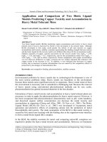
As described in DIN8580, manufacturing processes are classified into
six main groups: primary shaping, material forming, dividing, joining,
modifying material property and coating (Fig.2.1.1).
Primary shaping is the creation of an initial shape from the molten,
gaseous or formless solid state. Dividing is the local separation of mate-
rial. Joining is the assembly of individual workpieces to create sub-
assemblies and also the filling and saturation of porous workpieces.
Coating means the application of thin layers on components, for exam-
ple by galvanization, painting and foil wrapping. The purpose of modi-
fying material property is to alter material characteristics of a workpiece
coating
dividing
joining
modifyingmaterial
property
primaryshaping
forming
Fig. 2.1.1
Overview of production processes
Metal Forming Handbook / Schuler (c) Springer-Verlag Berlin Heidelberg 1998