Hướng dẫn kết nối màn hình HMI delta với PLC CIMON
Bạn đang xem bản rút gọn của tài liệu. Xem và tải ngay bản đầy đủ của tài liệu tại đây (117.31 KB, 2 trang )
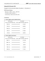
Series HMI Connection Manual
Hướng dẫn kết nối PLC với HMI Delta DOP
Cimon PLC
(This PLC is applicable to BP, XP series of PLC)
HMI Factory Setting:
Baud rate: 38400. 8. None. 1
Controller Station Number: 1
Control Area / Status Area: D00000/D00010
Connection
a. RS-232 (DOP-A/AE/AS, DOP-B Series)
DOP series
Controller
9 pin D-sub male (RS-232)
RXD (2)
(7) TXD
TXD (3)
(4) RXD
GND (5)
(2) GND
(3) RTS
(6) CTS
Definition of PLC Read/Write Address
a. Registers
Type
Format
Word No. (n)
Read/Write Range
Data Length Note
Input X
Xn
X000 – X511
Word
Output Y
Yn
Y000 – Y511
Word
General Purpose Relay M
Mn
M000 – M999
Word
General Purpose Relay L
Ln
L000 – L999
Word
Latch Relay K
Kn
K000 – K999
Word
Flags F
Fn
F000 – F127
Word
Timer (Set) TS
TSn
TS0000 – TS4095
Word
Timer (Current) TC
TCn
TC0000 – TC4095
Word
Counter (Set) CS
CSn
CS0000 – CS4095
Word
Counter (Current) CC
CCn
CC0000 – CC4095
Word
V1.00
Revision March, 2010
www.plc.today 15
Series HMI Connection Manual
Type
Format
Word No. (n)
General Purpose Word Data Dn
Read/Write Range
Data Length Note
D00000 – D31999
Word
S0 – S99
Byte
D
Step Controller S
Sn
1
b. Contacts
Format
Type
Word No. (n)
Bit No. (b)
Read/Write Range
Input X
Xnb
X0000 – X511F
Output Y
Ynb
Y0000 – Y511F
General Purpose Relay M
Mnb
M0000 – M999F
General Purpose Relay L
Lnb
L0000 – L999F
Latch Relay K
Knb
K0000 – K999F
Flags F
Fnb
F0000 – F127F
Timer Status T
Tb
T0000 – T4095
Counter Status C
Cb
C0000 – C4095
Note
NOTE
1)
The unit of PLC internal memory is byte and Device S is read in the unit of byte. It is
recommended NOT TO USE two consecutive devices S as the read address to prevent
occurrence of interference. For example, when choosing two numeric input device,
please use S24 and S26, do not use S24 and S25.
16
V1.00
Revision March, 2010