Hướng dẫn kết nối màn hình HMI delta với servo Copley
Bạn đang xem bản rút gọn của tài liệu. Xem và tải ngay bản đầy đủ của tài liệu tại đây (116.34 KB, 2 trang )
Series HMI Connection Manual
Hướng dẫn kết nối PLC với HMI Delta DOP
Copley Servo (Stepnet protocol)
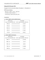
HMI Factory Setting:
Baud rate: 9600. 8. None. 1
Controller Station Number: 0
Control Area / Status Area: None/None
Connection
a. RS-232 (DOP-A/AE/AS, DOP-B Series)
DOP Series
Controller
9 pin D-sub male (RS-232)
RXD (2)
(7) TXD
TXD (3)
(4) RXD
GND (5)
(2) GND
(3) RTS
(6) CTS
Definition of PLC Read/Write Address
a. Registers
Format
Type
Word No. (n)
Read/Write Range
Data Length
Note
Ram memory R
Rnn
R00 – RFF
Double Word Hexadecimal
Flash memory F
Fnn
F00 – FFF
Double Word Hexadecimal
Internal Register IR
IRn
IR0 – IR31
Word
b. Contacts
Format
Type
Read/Write Range
Word No. (n)
Bit No. (b)
Note
BIT_DEVICE_RB
RBnn.b
RB00.0 – RBFF.31
1
BIT_DEVICE_FB
FBnn.b
FB00.0 – FBFF.31
1
BIT_DEVICE_T0
T0b
T00
2, 5
BIT_DEVICE_T1
T1b
T10
2, 5
V1.00
Revision March, 2010
www.plc.today 17
Series HMI Connection Manual
Format
Type
Read/Write Range
Word No. (n)
Bit No. (b)
Note
BIT_DEVICE_T2
T2b
T20
2, 5
BIT_DEVICE_RST
RSTb
RST0
3, 5
BIT_DEVICE_CPR
CPRnn
CPR00 – CPRFF
Hexadecimal, 4, 5
BIT_DEVICE_CPF
CPFnn
CPF00 – CPFFF
Hexadecimal, 4, 5
NOTE
1)
RB and FB are the bit access of Ram/Flash memory. Therefore, RB0x21.14 indicates bit
14 of Ram memory 0x21.
2)
T0, T1 and T2 are virtual devices for simulating Trajectory Generator Command. The
number of 0, 1 and 2 indicates the subcommand of that command, so only bit 0 is
acceptable.
3)
RST is for simulating Reset Command, so only bit 0 is acceptable.
4)
CPR and CPF are for simulating Copy Command of Ram and Flash individually. The
address (n) after CPR and CPF is just the copy address for Ram/Flash memory. For
example, CPR12 indicates that the content of Ram memory 0x12 will be copied into
Flash memory 0x12 and CPF6A indicates that the content of Flash memory 0x6A will be
copied into Ram memory 0x6A.
5)
18
T0, T1, T2, RST, CPR, CPF are all read-only and they can not be used on Reset button.
V1.00
Revision March, 2010